Page 267 of 687

Downloaded from www.Manualslib.com manuals search engine 5-6 BRAKES
Excessive pedal travel
(Pedal stroke too
large)Partial brake system failure Check brake systems and repair as
necessary.
Insufficient fluid in master cylinder reservoirs Fill reservoirs with approved brake
fluid.
Check for leaks and air in brake
systems.
Check warning light. Bleed system
if required.
Air in system (pedal soft/spongy) Bleed system.
Rear brake system not adjusted (malfunctioning
auto adjusting mechanism)Repair auto adjusting mechanism.
Adjust rear brakes.
Bent brake shoes Replace brake shoes.
Worn rear brake shoes Replace brake shoes.
Dragging brakes (A
very light drag is
present in all disc
brakes immediately
after pedal is released)Master cylinder pistons not returning correctly Repair master cylinder.
Restricted brake tubes or hoses Check for soft hoses or damaged
tubes and replace with new hoses
and/or new brake tubes.
Incorrect parking brake adjustment on rear
brakesCheck and adjust to correct specifi-
cations.
Weakened or broken return springs in the brake Replace.
Sluggish parking-brake cables or linkage Repair or replace.
Wheel cylinder or caliper piston sticking Repair as necessary.
Malfunctioning ABS, if equipped with ABS Check system and replace as nec-
essary.
Pedal pulsation (Pedal
pulsates when
depressed for brak-
ing.) Damaged or loose wheel bearings Replace wheel bearings.
Distorted steering knuckle or rear axle shafts Replace knuckle or rear axle shaft.
Excessive disc lateral runout Check per instructions. If not within
specifications, replace or machine
the disc.
Parallelism not within specifications Check per instructions. If not with
specifications, replace or machine
the disc.
Rear drums out of round. Check runout.
Repair or replace drum as neces-
sary.
Braking noise
Glazed shoe linings, or foreign matters stuck to
liningsRepair or replace brake shoe.
Worn or distorted shoe linings Replace brake shoe (or pad).
Loose front wheel bearings Replace wheel bearing.
Distorted backing plates or loose mounting
boltsReplace or retighten securing bolts.
Brake warning light
turns on after engine
startParking brake applied Release parking brake and check
that brake warning light turns off.
Insufficient amount of brake fluid Add brake fluid.
Brake fluid leaking from brake line Investigate leaky point, correct it
and add brake fluid.
Brake warning light circuit faulty Repair circuit. Condition Possible Cause Correction
Page 269 of 687

Downloaded from www.Manualslib.com manuals search engine 5-8 BRAKES
Brake Pedal Free Height Adjustment
1) Check brake pedal free height.
If it is not within specification, check and adjust following item
2) and 3).
Brake pedal free height “a” from wall
LH steering vehicle : 221 – 227 mm (8.70 – 8.94 in.)
RH steering vehicle : 217 – 223 mm (8.54 – 8.78 in.)
2) Check measurement between booster mounting surface and
center of clevis pin hole. When booster push rod clevis has
been reinstalled, it is important that the measurement is
adjusted. (Refer to “Brake Booster Inspection and Adjust-
ment” in this section.)
3) Check stop light switch position. Adjust it if it is out of specifi-
cation.
Brake Pedal Play Check
Pedal play should be within specification below.
If out of specification, check stop light switch for proper installation
position and adjust if necessary.
Also check pedal shaft bolt and master cylinder pin installation for
looseness and replace if defective.
Brake pedal play “a” : 1 – 8 mm (0.04 – 0.31 in.)
Stop Light Switch Adjustment
Adjustment should be made as follows when installing switch. Pull
up brake pedal toward you and while holding it there, adjust
switch position so that clearance between end of thread and
brake pedal is specified. Then tighten lock nut to specified torque.
Clearance between brake pedal and stop light switch
“c” : 1.5 – 2.0 mm (0.06 – 0.08 in.)
Tightening torque
Stop light switch lock nut
(a) : 6.5 N·m (0.65 kg-m, 4.7 lb-ft)
Page 277 of 687

Downloaded from www.Manualslib.com manuals search engine 5-16 BRAKES
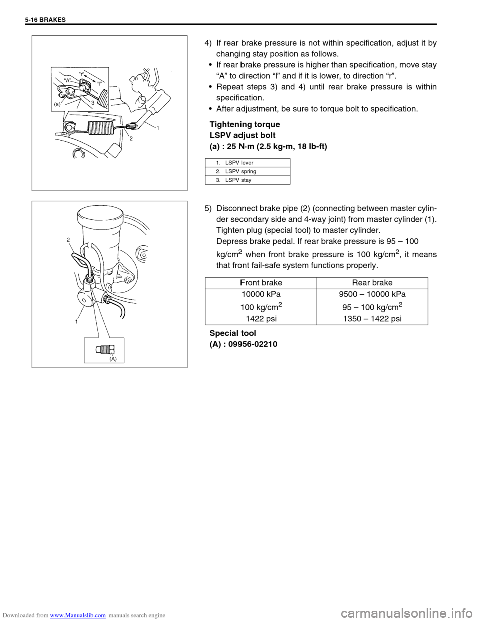
4) If rear brake pressure is not within specification, adjust it by
changing stay position as follows.
If rear brake pressure is higher than specification, move stay
“A” to direction “l” and if it is lower, to direction “r”.
Repeat steps 3) and 4) until rear brake pressure is within
specification.
After adjustment, be sure to torque bolt to specification.
Tightening torque
LSPV adjust bolt
(a) : 25 N·m (2.5 kg-m, 18 Ib-ft)
5) Disconnect brake pipe (2) (connecting between master cylin-
der secondary side and 4-way joint) from master cylinder (1).
Tighten plug (special tool) to master cylinder.
Depress brake pedal. If rear brake pressure is 95 – 100
kg/cm
2 when front brake pressure is 100 kg/cm2, it means
that front fail-safe system functions properly.
Special tool
(A) : 09956-02210
1. LSPV lever
2. LSPV spring
3. LSPV stay
Front brake Rear brake
10000 kPa
100 kg/cm
2
1422 psi9500 – 10000 kPa
95 – 100 kg/cm
2
1350 – 1422 psi
Page 280 of 687
Downloaded from www.Manualslib.com manuals search engine BRAKES 5-19
PIPE
Inspect the tube for damage, cracks, dents and corrosion. If any
defect is found, replace it.
Front Disc Brake
1. Caliper pin bolt 10. Carrier bolt
2. Boot11. Brake caliper carrier
3. Cylinder slide bush
: Apply rubber grease to mating surface of caliper12. Pad clip
4. Bleeder plug cap 13. Disc brake caliper
5. Bleeder plug 14. Disc brake pad
6. Anti noise shim 15. Piston seal
: Apply brake fluid to all around part of piston seal
7. Disc brake piston
: Apply brake fluid to contact surface of cylinderTightening torque
8. Cylinder bootDo not reuse.
9. Seat ring (boot ring)
Page 281 of 687
Downloaded from www.Manualslib.com manuals search engine 5-20 BRAKES
Brake pad
REMOVAL
1) Hoist vehicle and remove wheel.
2) Remove caliper pin bolts (2).
3) Remove caliper (1) from caliper carrier.
4) Remove pads (3).
INSPECTION
Check pad lining for wear. When wear exceeds limit, replace with
new one.
Brake pad thickness (lining + pad rim)
Standard : 15 mm (0.59 in.)
Limit : 7 mm (0.28 in.)
1. Caliper
3. Disc
NOTE:
Hang removed caliper (1) with a wire hook (2) or the like
so as to prevent brake hose from bending and twisting
excessively or being pulled.
Don’t operate brake pedal with pads (3) removed.
CAUTION:
Never polish pad lining with sandpaper. If lining is pol-
ished with sandpaper, hard particles of sandpaper will be
deposited in lining and may damage disc. When pad lin-
ing requires correction, replace it with a new one.
NOTE:
When pads are removed, visually inspect caliper for
brake fluid leak. Correct leaky point, if any.
Page 282 of 687
Downloaded from www.Manualslib.com manuals search engine BRAKES 5-21
INSTALLATION
1) Install pad shim (1) (to outside pad) and pads (2) to caliper
carrier (3).
2) Install caliper and torque caliper pin bolts (1) to specification.
Tightening torque
Brake caliper pin bolts
(a) : 22 N·m (2.2 kg-m, 16.0 Ib-ft)
3) Install wheel and torque front wheel nuts to specification.
Tightening torque
Wheel nuts
(a) : 95 N·m (9.5 kg-m, 69.0 lb-ft)
4) Upon completion of installation, perform brake test.NOTE:
See NOTE at the beginning of this section.
NOTE:
Make sure that boots are fit into groove securely.
Page 283 of 687

Downloaded from www.Manualslib.com manuals search engine 5-22 BRAKES
Caliper assembly
REMOVAL
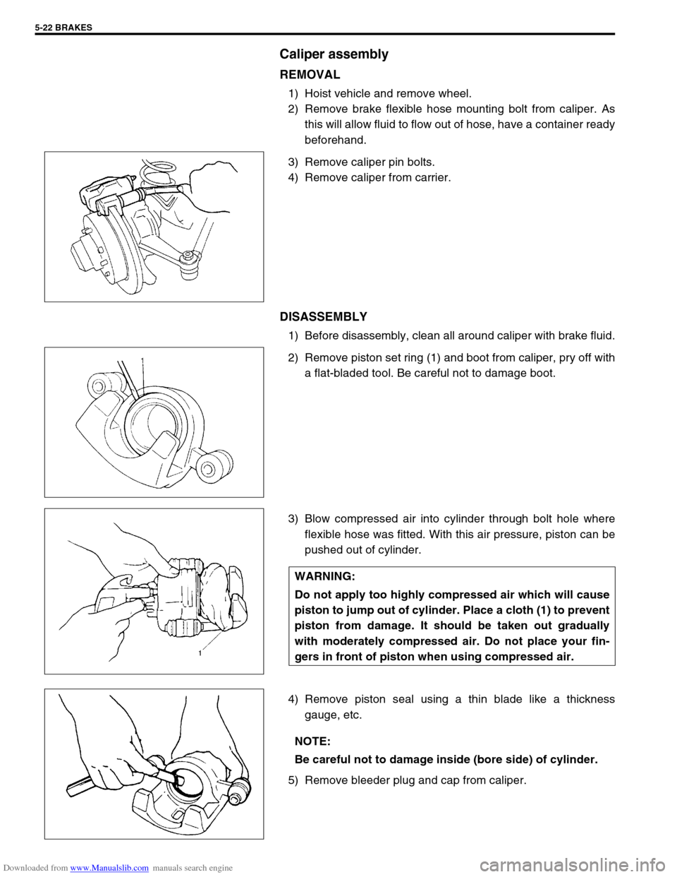
1) Hoist vehicle and remove wheel.
2) Remove brake flexible hose mounting bolt from caliper. As
this will allow fluid to flow out of hose, have a container ready
beforehand.
3) Remove caliper pin bolts.
4) Remove caliper from carrier.
DISASSEMBLY
1) Before disassembly, clean all around caliper with brake fluid.
2) Remove piston set ring (1) and boot from caliper, pry off with
a flat-bladed tool. Be careful not to damage boot.
3) Blow compressed air into cylinder through bolt hole where
flexible hose was fitted. With this air pressure, piston can be
pushed out of cylinder.
4) Remove piston seal using a thin blade like a thickness
gauge, etc.
5) Remove bleeder plug and cap from caliper.
WARNING:
Do not apply too highly compressed air which will cause
piston to jump out of cylinder. Place a cloth (1) to prevent
piston from damage. It should be taken out gradually
with moderately compressed air. Do not place your fin-
gers in front of piston when using compressed air.
NOTE:
Be careful not to damage inside (bore side) of cylinder.
Page 285 of 687

Downloaded from www.Manualslib.com manuals search engine 5-24 BRAKES
ASSEMBLY
1) Check that slide bushes and boots for wear, corrosion, dam-
age, movement or deterioration. If it is found faulty, correct or
replace.
Apply rubber grease to bush outer surface. And then make
sure that each bush slides easily through each caliper bolt
hole.
2) Tighten bleeder plug to specified torque and install cap.
Tightening torque
Front caliper bleeder plug
(a) : 11 N·m (1.1 g-m, 8.0 lb-ft)
3) Piston seal is used to seal piston and cylinder and to adjust
clearance between pad and disc. Replace with a new one at
every overhaul. Fit piston seal into groove in cylinder taking
care not to twist it.
4) Before inserting piston (2) into cylinder, install new boot (1)
onto piston (2) as shown.
“A” : 2-grooved side directed inside
“B” : 3-grooved side directed outside CAUTION:
Wash each part cleanly before installation in the same
fluid as the one used in master cylinder reservoir.
Never use other fluid or thinner.
Before installing piston and piston seal to cylinder,
apply fluid to them.
After reassembling brake lines, bleed air from them.
NOTE:
Where temperature gets as low as – 30 °C (– 22 °F) in cold
weather, use rubber grease whose viscosity varies very
little even at – 40 °C (– 40 °F).
1. Apply rubber grease