2005 SUZUKI JIMNY battery
[x] Cancel search: batteryPage 650 of 687

Downloaded from www.Manualslib.com manuals search engine IGNITION SYSTEM (ELECTRONIC IGNITION SYSTEM) 6F-1
6G
6F2
6G
6H
7D
7E
7F
7A1
7A1
7D
7E
7F
8A
8B
8C
8D
8E
6K
6F
7A
10
10A
10B
SECTION 6F
IGNITION SYSTEM
(ELECTRONIC IGNITION SYSTEM)
CONTENTS
General Description ........................................ 6F-2
Diagnosis ......................................................... 6F-3
On-Vehicle Service.......................................... 6F-5
Ignition Spark Test ........................................ 6F-5
High-tension Cords ....................................... 6F-5
Spark Plugs ................................................... 6F-6Ignition Coil Assembly (Including Ignitor) ...... 6F-7
Crankshaft Position Sensor (CKP Sensor) ... 6F-8
Ignition Timing............................................... 6F-8
Special Tools ................................................. 6F-10
Tightening Torque Specification ................. 6F-10
WARNING:
For vehicles equipped with Supplemental Restraint (Air Bag) System:
Service on and around the air bag system components or wiring must be performed only by an
authorized SUZUKI dealer. Refer to “Air Bag System Components and Wiring Location View” under
“General Description” in air bag system section in order to confirm whether you are performing ser-
vice on or near the air bag system components or wiring. Please observe all WARNINGS and “Ser-
vice Precautions” under “On-Vehicle Service” in air bag system section before performing service
on or around the air bag system components or wiring. Failure to follow WARNINGS could result in
unintentional activation of the system or could render the system inoperative. Either of these two
conditions may result in severe injury.
Technical service work must be started at least 90 seconds after the ignition switch is turned to the
“LOCK” position and the negative cable is disconnected from the battery. Otherwise, the system
may be activated by reserve energy in the Sensing and Diagnostic Module (SDM).
Page 656 of 687

Downloaded from www.Manualslib.com manuals search engine IGNITION SYSTEM (ELECTRONIC IGNITION SYSTEM 6F-7
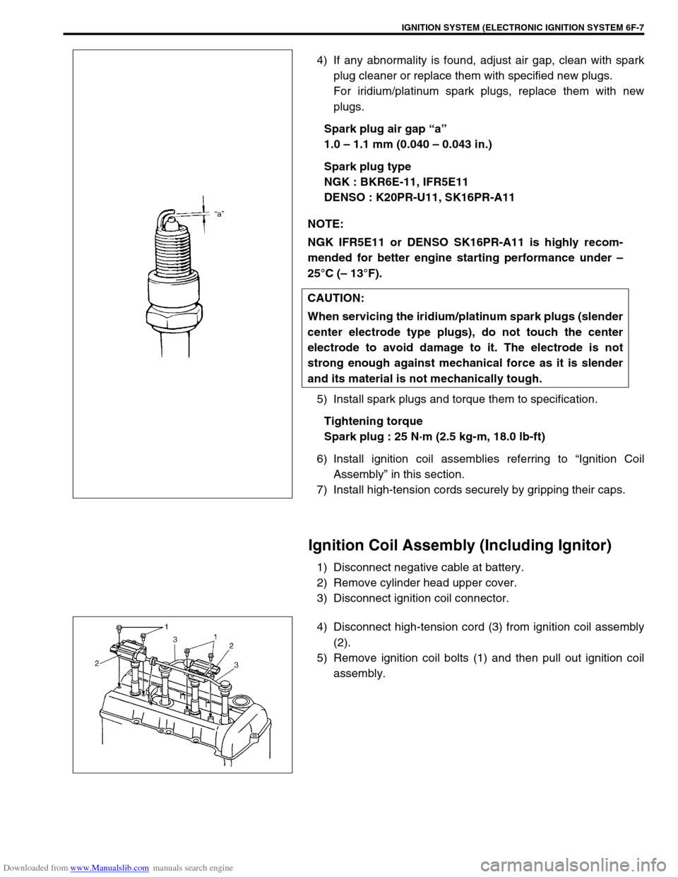
4) If any abnormality is found, adjust air gap, clean with spark
plug cleaner or replace them with specified new plugs.
For iridium/platinum spark plugs, replace them with new
plugs.
Spark plug air gap “a”
1.0 – 1.1 mm (0.040 – 0.043 in.)
Spark plug type
NGK : BKR6E-11, IFR5E11
DENSO : K20PR-U11, SK16PR-A11
5) Install spark plugs and torque them to specification.
Tightening torque
Spark plug : 25 N·m (2.5 kg-m, 18.0 lb-ft)
6) Install ignition coil assemblies referring to “Ignition Coil
Assembly” in this section.
7) Install high-tension cords securely by gripping their caps.
Ignition Coil Assembly (Including Ignitor)
1) Disconnect negative cable at battery.
2) Remove cylinder head upper cover.
3) Disconnect ignition coil connector.
4) Disconnect high-tension cord (3) from ignition coil assembly
(2).
5) Remove ignition coil bolts (1) and then pull out ignition coil
assembly. NOTE:
NGK IFR5E11 or DENSO SK16PR-A11 is highly recom-
mended for better engine starting performance under –
25°C (– 13°F).
CAUTION:
When servicing the iridium/platinum spark plugs (slender
center electrode type plugs), do not touch the center
electrode to avoid damage to it. The electrode is not
strong enough against mechanical force as it is slender
and its material is not mechanically tough.
Page 659 of 687

Downloaded from www.Manualslib.com manuals search engine 6F-10 IGNITION SYSTEM (ELECTRONIC IGNITION SYSTEM)
Special Tools
Tightening Torque Specification
09931-76011 09931-76030
Tech 1A kit (SUZUKI scan
tool) (See NOTE “A”.)Mass storage cartridge for
Tech 1A16/14 pin DLC adapter for
Tech 1ATech 2 kit (SUZUKI scan
tool) (See NOTE “B”. )
NOTE:
“A” : This kit includes the following items and substitutes for the Tech 2 kit.
1. Storage case, 2. Operator’s manual, 3. Tech 1A, 4. DLC cable (14/26 pin, 09931-76040),
5. Test lead/probe, 6. Power source cable, 7. DLC cable adaptor, 8. Self-test adaptor
“B” : This kit includes the following items and substitutes for the Tech 1A kit.
1. Tech 2, 2. PCMCIA card, 3. DLC cable, 4. SAE 16/19 adapter, 5. Cigarette cable,
6. DLC loopback adapter, 7. Battery power cable, 8. RS232 cable, 9. RS232 adapter,
10. RS232 loopback connector, 11. Storage case, 12. Power supply
Fastening partTightening torque
Nm kg-m lb-ft
Spark plug 25 2.5 18.0
Page 660 of 687

Downloaded from www.Manualslib.com manuals search engine CRANKING SYSTEM 6G-1
6F1
6F2
6H
7C1
7D
7E
7C1
7B1
7C1
7D
7E
7F
8A
8B
8C
8D
8E
6G
7A1
10A
10B
SECTION 6G
CRANKING SYSTEM
CONTENTS
General Description ....................................... 6G-2
Cranking Circuit ............................................ 6G-2
Diagnosis ........................................................ 6G-2
Diagnosis Table ........................................... 6G-2Performance Test .........................................6G-4
On-Vehicle Service .........................................6G-5
Starting Motor ...............................................6G-5
Specifications..................................................6G-7
WARNING:
For vehicles equipped with Supplemental Restraint (Air Bag) System:
Service on and around the air bag system components or wiring must be performed only by an
authorized SUZUKI dealer. Refer to “Air Bag System Components and Wiring Location View” under
“General Description” in air bag system section in order to confirm whether you are performing ser-
vice on or near the air bag system components or wiring. Please observe all WARNINGS and “Ser-
vice Precautions” under “On-Vehicle Service” in air bag system section before performing service
on or around the air bag system components or wiring. Failure to follow WARNINGS could result in
unintentional activation of the system or could render the system inoperative. Either of these two
conditions may result in severe injury.
Technical service work must be started at least 90 seconds after the ignition switch is turned to the
“LOCK” position and the negative cable is disconnected from the battery. Otherwise, the system
may be activated by reserve energy in the Sensing and Diagnostic Module (SDM).
NOTE:
Starting motor varies depending on specifications, etc. Therefore, be sure to check model and speci-
fication of vehicle being serviced before replacing parts.
Page 661 of 687

Downloaded from www.Manualslib.com manuals search engine 6G-2 CRANKING SYSTEM
General Description
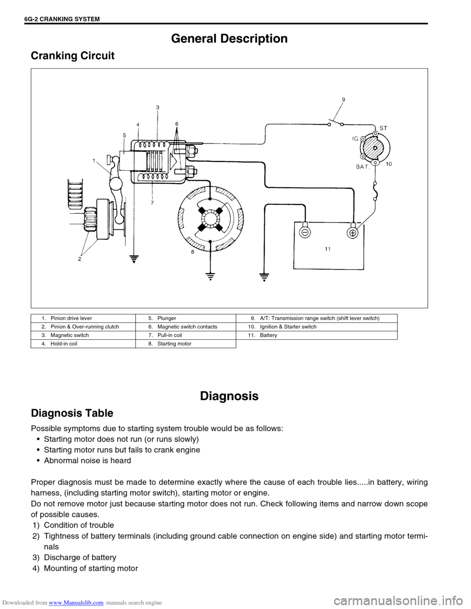
Cranking Circuit
Diagnosis
Diagnosis Table
Possible symptoms due to starting system trouble would be as follows:
Starting motor does not run (or runs slowly)
Starting motor runs but fails to crank engine
Abnormal noise is heard
Proper diagnosis must be made to determine exactly where the cause of each trouble lies.....in battery, wiring
harness, (including starting motor switch), starting motor or engine.
Do not remove motor just because starting motor does not run. Check following items and narrow down scope
of possible causes.
1) Condition of trouble
2) Tightness of battery terminals (including ground cable connection on engine side) and starting motor termi-
nals
3) Discharge of battery
4) Mounting of starting motor
1. Pinion drive lever 5. Plunger 9. A/T: Transmission range switch (shift lever switch)
2. Pinion & Over-running clutch 6. Magnetic switch contacts 10. Ignition & Starter switch
3. Magnetic switch 7. Pull-in coil 11. Battery
4. Hold-in coil 8. Starting motor
Page 662 of 687

Downloaded from www.Manualslib.com manuals search engine CRANKING SYSTEM 6G-3
Condition Possible Cause Correction
Motor not running
(No operating sound of
magnetic switch)Shift lever switch is not in P or N, or not adjusted
(A/T)Shift in P or N, or adjust switch.
Battery run down Recharge battery.
Battery voltage too low due to battery deteriora-
tionReplace battery.
Poor contact in battery terminal connection Retighten or replace.
Loose grounding cable connection Retighten.
Fuse set loose or blown off Tighten or replace.
Poor contacting action of ignition switch and mag-
netic switchReplace.
Lead wire coupler loose in place Retighten.
Open-circuit between ignition switch and magnetic
switchRepair.
Open-circuit in pull-in coil Replace magnetic switch.
Brushes are seating poorly or worn down Repair or replace.
Poor sliding of plunger and/or pinion Repair.
Motor not running
(Operating sound of
magnetic switch
heard)Battery run down Recharge battery.
Battery voltage too low due to battery deteriora-
tionReplace battery.
Loose battery cable connections Retighten.
Burnt main contact point, or poor contacting action
of magnetic switchReplace magnetic switch.
Brushes are seating poorly or worn down Repair or replace.
Weakened brush spring Replace.
Burnt commutator Replace armature.
Layer short-circuit of armature Replace.
Crankshaft rotation obstructed Repair.
Starting motor running
but too slow (small
torque) (If battery and
wiring are satisfac-
tory, inspect starting
motor)Insufficient contact of magnetic switch main con-
tactsReplace magnetic switch.
Layer short-circuit of armature Replace.
Disconnected, burnt or worn commutator Repair commutator or replace
armature.
Worn brushes Replace brush.
Weakened brush springs Replace spring.
Burnt or abnormally worn end bush Replace bush.
Starting motor run-
ning, but not cranking
engineWorn pinion tip Replace over-running clutch.
Poor sliding of over-running clutch Repair.
Over-running clutch slipping Replace over-running clutch.
Worn teeth of ring gear Replace flywheel (M/T) or drive
plate (A/T).
Noise
Abnormally worn bush Replace bush.
Worn pinion or worn teeth of ring gear Replace pinion or flywheel
(M/T) or drive plate (A/T).
Poor sliding of pinion (failure in return movement) Repair or replace.
Worn internal or planetary gear teeth Replace.
Lack of oil in each part Lubricate.
Page 663 of 687

Downloaded from www.Manualslib.com manuals search engine 6G-4 CRANKING SYSTEM
Performance Test
PULL-IN TEST
Connect battery to magnetic switch as shown.
Check that plunger and pinion move outward.
If plunger and pinion don’t move, replace magnetic switch.
HOLD-IN TEST
While connected as above with plunger out, disconnect negative
lead from terminal “M”.
Check that plunger and pinion remain out.
If plunger and pinion return inward, replace magnetic switch.
PLUNGER AND PINION RETURN TEST
Disconnect negative lead from starting motor body.
Check that plunger and pinion return inward.
If plunger and pinion don’t return, replace magnetic switch. Starting motor does
not stop runningFused contact points of magnetic switch Replace magnetic switch.
Short-circuit between turns of magnetic switch coil
(layer short-circuit)Replace magnetic switch.
Failure of returning action in ignition switch Replace.
CAUTION:
Each test must be performed within 3 – 5 seconds to
avoid coil from burning.
NOTE:
Before testing, disconnect lead wire from terminal M.
1. Terminal “S”
2. Terminal “M”
3. Lead wire (switch to motor)
Condition Possible Cause Correction
Page 664 of 687

Downloaded from www.Manualslib.com manuals search engine CRANKING SYSTEM 6G-5
NO-LOAD PERFORMANCE TEST
Connect battery and ammeter to starter as shown.
Check that starter rotates smoothly and steadily with pinion mov-
ing out. Check that ammeter indicates specified current.
Specified current (No-load performance test)
: 90 A MAX. at 11 V
On-Vehicle Service
Starting Motor
DISMOUNTING
1) Disconnect negative (–) battery lead at battery.
2) Disconnect magnetic switch lead wire (6) and battery cable (7) from starting motor terminals.
3) Remove starting motor mount bolts (4) and nut (5).
4) Remove starting motor (1).
REMOUNTING
Reverse the dismounting procedure.
1. Starting motor 3. Transmission case 5. Starting motor mounting nut 7. Battery cable
2. Clutch housing upper plate 4. Starting motor mounting bolt 6. Magnetic switch lead wire Tightening Torque