Page 502 of 687
Downloaded from www.Manualslib.com manuals search engine ENGINE MECHANICAL (M13 ENGINE) 6A1-21
Exhaust Manifold
REMOVAL
1) Disconnect negative cable at battery.
2) Disconnect heated oxygen sensor coupler (1) (if equipped)
and detach it from its stay.
3) Remove exhaust manifold cover (2).
4) Remove exhaust manifold stiffener (1).
1. Exhaust manifold 4. Exhaust manifold cover Tightening torque
2. Exhaust manifold gasket 5. Engine hook Do not reuse.
3. Heated oxygen sensor (if equipped) 6. Exhaust manifold mounting nut
WARNING:
To avoid danger of being burned, do not service exhaust
system while it is still hot. Service should be performed
after system cools down.
Page 504 of 687
Downloaded from www.Manualslib.com manuals search engine ENGINE MECHANICAL (M13 ENGINE) 6A1-23
3) Install exhaust manifold stiffener (1).
Tighten exhaust manifold stiffener bolts to specified torque.
Tightening torque
Exhaust manifold stiffener bolts
(a) : 50 N·m (5.0 kg-m, 36.5 lb-ft)
4) Install exhaust manifold cover (1).
5) Connect heated oxygen sensor coupler (2) and fit coupler to
bracket securely (if equipped).
6) Connect negative cable at battery.
7) Check exhaust system for exhaust gas leakage.
Page 509 of 687
Downloaded from www.Manualslib.com manuals search engine 6A1-28 ENGINE MECHANICAL (M13 ENGINE)
Timing Chain Cover
REMOVAL
1) Disconnect negative cable at battery.
2) Remove A/C compressor and/or P/S pump belt (if
equipped).
3) Remove generator belt.
4) Drain engine oil.
[A] : Sealant application
amount3. Oil seal
: Apply engine oil to oil seal lip.8. Cylinder head cover
: Apply sealant 99000-31150 to the sealing
point for timing chain cover mating surface
and cylinder head gasket sealing point.
Refer to “Cylinder Head Cover Installation”.
“a” : 3 mm (0.12 in.) 4. Timing chain cover Tightening torque
: Apply sealant 99000-31140 to the mating surface
of cylinder and cylinder head.
: Apply sealant 99000-31150 to the mating surface
of timing chain cover referring to the figure of Step
1) in INSTALLATION.
“b” : 2 mm (0.08 in.) 5. Pin Do not reuse.
1. Crankshaft pulley bolt 6. Cylinder head cover gasket
2. Crankshaft pulley 7. Timing chain cover mounting bolts
Page 514 of 687
Downloaded from www.Manualslib.com manuals search engine ENGINE MECHANICAL (M13 ENGINE) 6A1-33
Oil Pump
REMOVAL
1) Disconnect negative cable at battery.
2) Remove timing chain cover, referring to “Timing Chain
Cover” in this section.
DISASSEMBLY
1) Remove rotor plate (1) by removing its mounting bolts.
[A] : Sealant application
amount4. Timing chain cover 10. Circlip
: Apply sealant 99000-31140 to the mating surface of cylinder and
cylinder head.
: Apply sealant 99000-31150 to mating surface of timing chain cover
referring to the figure of Step 1) in “Timing Chain Cover Installation”.
“a” : 3 mm (0.12 in.) 5. Pin 11. Oil pump mounting bolt
“b” : 2 mm (0.08 in.) 6. Oil seal 12. Timing chain cover mounting bolts
1. Rotor plate 7. Relief valve Tightening torque
2. Outer rotor 8. Spring Do not reuse.
3. Inner rotor 9. Retainer Apply thin coat of engine oil to sliding
surface of each parts.
Page 530 of 687

Downloaded from www.Manualslib.com manuals search engine ENGINE MECHANICAL (M13 ENGINE) 6A1-49
REMOVAL
1) Relieve fuel pressure referring to “Fuel Pressure Relief Pro-
cedure” in Section 6.
2) Disconnect negative cable at battery.
3) Drain engine oil.
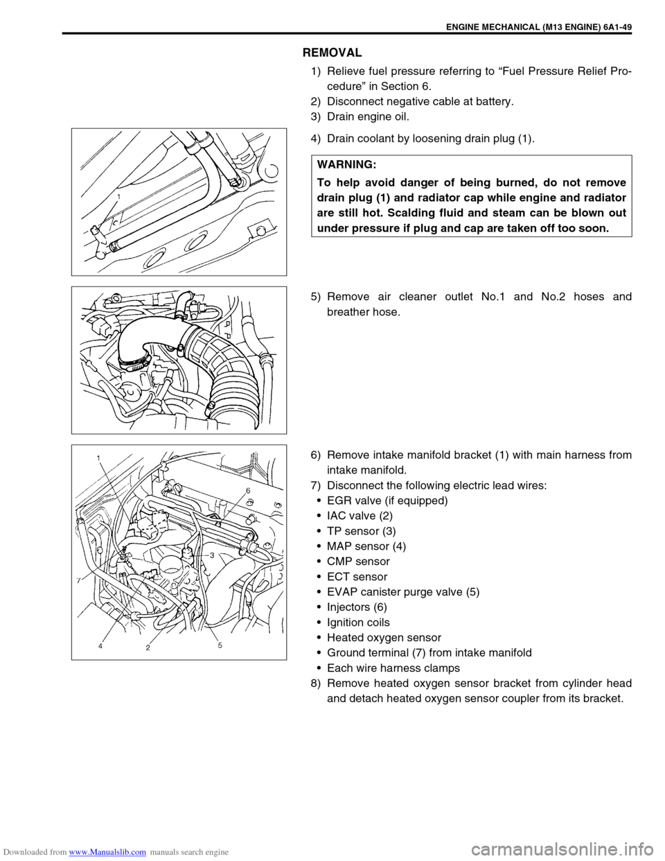
4) Drain coolant by loosening drain plug (1).
5) Remove air cleaner outlet No.1 and No.2 hoses and
breather hose.
6) Remove intake manifold bracket (1) with main harness from
intake manifold.
7) Disconnect the following electric lead wires:
EGR valve (if equipped)
IAC valve (2)
TP sensor (3)
MAP sensor (4)
CMP sensor
ECT sensor
EVAP canister purge valve (5)
Injectors (6)
Ignition coils
Heated oxygen sensor
Ground terminal (7) from intake manifold
Each wire harness clamps
8) Remove heated oxygen sensor bracket from cylinder head
and detach heated oxygen sensor coupler from its bracket. WARNING:
To help avoid danger of being burned, do not remove
drain plug (1) and radiator cap while engine and radiator
are still hot. Scalding fluid and steam can be blown out
under pressure if plug and cap are taken off too soon.
Page 542 of 687

Downloaded from www.Manualslib.com manuals search engine ENGINE MECHANICAL (M13 ENGINE) 6A1-61
6) Install exhaust manifold stiffener and exhaust pipe referring
to “Exhaust Manifold” in this section.
7) Install camshafts, timing chain and chain cover referring to
“Camshaft, Tappet and Shim”, “Timing Chain and Chain
Tensioner” and “Timing Chain Cover” in this section.
8) Install cylinder head cover and oil pan referring to “Cylinder
Head Cover” and “Oil Pan and Oil Pump Strainer” in this sec-
tion.
9) Install intake manifold stiffener and connect each hoses and
electric lead wires securely.
10) Install air cleaner outlet hoses.
11) Install radiator with cooling fan and connect A/T fluid hoses
(vehicle with A/T), radiator inlet and outlet hoses referring to
“Water Pump Belt and Cooling Fan” and “Radiator” in Sec-
tion 6B.
12) Adjust generator belt tension referring to “Water Pump Belt
Tension” in Section 6B.
13) Adjust A/C compressor and/or P/S pump belt tension (if
equipped) referring to “Compressor Drive Belt” in Section 1B
or “Power Steering Belt” in Section 3B1.
14) Adjust accelerator cable play referring to “Accelerator Cable
Adjustment” in Section 6E.
15) Check to ensure that all removed parts are back in place.
Reinstall any necessary parts which have not been rein-
stalled.
16) Refill cooling system with coolant, engine with engine oil and
A/T with specified A/T fluid (vehicle with A/T).
17) Connect negative cable at battery.
18) Verify that there is no fuel leakage, coolant leakage, oil leak-
age, A/T fluid leakage (vehicle with A/T) and exhaust gas
leakage at each connection.
Page 543 of 687

Downloaded from www.Manualslib.com manuals search engine 6A1-62 ENGINE MECHANICAL (M13 ENGINE)
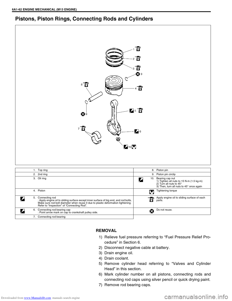
Pistons, Piston Rings, Connecting Rods and Cylinders
REMOVAL
1) Relieve fuel pressure referring to “Fuel Pressure Relief Pro-
cedure” in Section 6.
2) Disconnect negative cable at battery.
3) Drain engine oil.
4) Drain coolant.
5) Remove cylinder head referring to “Valves and Cylinder
Head” in this section.
6) Mark cylinder number on all pistons, connecting rods and
connecting rod caps using silver pencil or quick drying paint.
7) Remove rod bearing caps.
1. Top ring8. Piston pin
2. 2nd ring9. Piston pin circlip
3. Oil ring10. Bearing cap nut
1) Tighten all nuts to 15 N·m (1.5 kg-m)
2) Turn all nuts to 45°
3) Then, turn all nuts to 45° once again
4. PistonTightening torque
5. Connecting rod
: Apply engine oil to sliding surface except inner surface of big end, and rod bolts.
Make sure rod bolt diameter when reuse it due to plastic deformation tightening.
Refer to “Inspection” of “Connecting Rod”.Apply engine oil to sliding surface of each
parts.
6. Connecting rod bearing cap
: Point arrow mark on cap to crankshaft pulley side.Do not reuse.
7. Connecting rod bearing
Page 552 of 687

Downloaded from www.Manualslib.com manuals search engine ENGINE MECHANICAL (M13 ENGINE) 6A1-71
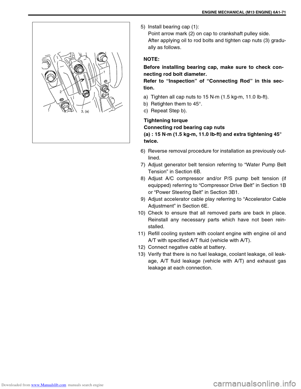
5) Install bearing cap (1):
Point arrow mark (2) on cap to crankshaft pulley side.
After applying oil to rod bolts and tighten cap nuts (3) gradu-
ally as follows.
a) Tighten all cap nuts to 15 N·m (1.5 kg-m, 11.0 lb-ft).
b) Retighten them to 45°.
c) Repeat Step b).
Tightening torque
Connecting rod bearing cap nuts
(a) : 15 N·m (1.5 kg-m, 11.0 lb-ft) and extra tightening 45°
twice.
6) Reverse removal procedure for installation as previously out-
lined.
7) Adjust generator belt tension referring to “Water Pump Belt
Tension” in Section 6B.
8) Adjust A/C compressor and/or P/S pump belt tension (if
equipped) referring to “Compressor Drive Belt” in Section 1B
or “Power Steering Belt” in Section 3B1.
9) Adjust accelerator cable play referring to “Accelerator Cable
Adjustment” in Section 6E.
10) Check to ensure that all removed parts are back in place.
Reinstall any necessary parts which have not been rein-
stalled.
11) Refill cooling system with coolant engine with engine oil and
A/T with specified A/T fluid (vehicle with A/T).
12) Connect negative cable at battery.
13) Verify that there is no fuel leakage, coolant leakage, oil leak-
age, A/T fluid leakage (vehicle with A/T) and exhaust gas
leakage at each connection. NOTE:
Before installing bearing cap, make sure to check con-
necting rod bolt diameter.
Refer to “Inspection” of “Connecting Rod” in this sec-
tion.