2005 SUZUKI JIMNY Speed
[x] Cancel search: SpeedPage 620 of 687
Downloaded from www.Manualslib.com manuals search engine ENGINE AND EMISSION CONTROL SYSTEM 6E-15
On-Vehicle Service
Accelerator cable adjustment
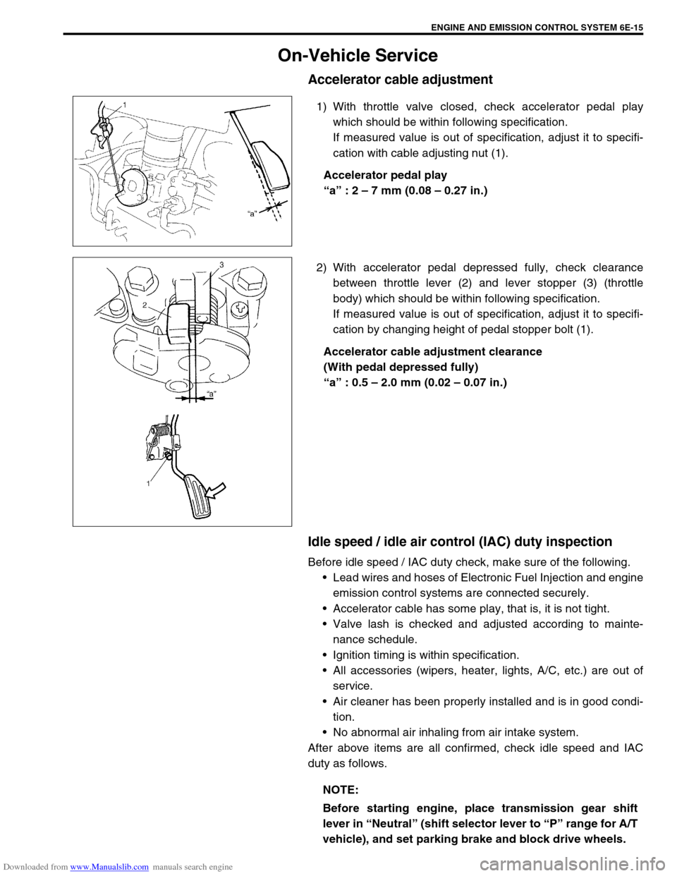
1) With throttle valve closed, check accelerator pedal play
which should be within following specification.
If measured value is out of specification, adjust it to specifi-
cation with cable adjusting nut (1).
Accelerator pedal play
“a” : 2 – 7 mm (0.08 – 0.27 in.)
2) With accelerator pedal depressed fully, check clearance
between throttle lever (2) and lever stopper (3) (throttle
body) which should be within following specification.
If measured value is out of specification, adjust it to specifi-
cation by changing height of pedal stopper bolt (1).
Accelerator cable adjustment clearance
(With pedal depressed fully)
“a” : 0.5 – 2.0 mm (0.02 – 0.07 in.)
Idle speed / idle air control (IAC) duty inspection
Before idle speed / IAC duty check, make sure of the following.
Lead wires and hoses of Electronic Fuel Injection and engine
emission control systems are connected securely.
Accelerator cable has some play, that is, it is not tight.
Valve lash is checked and adjusted according to mainte-
nance schedule.
Ignition timing is within specification.
All accessories (wipers, heater, lights, A/C, etc.) are out of
service.
Air cleaner has been properly installed and is in good condi-
tion.
No abnormal air inhaling from air intake system.
After above items are all confirmed, check idle speed and IAC
duty as follows.
NOTE:
Before starting engine, place transmission gear shift
lever in “Neutral” (shift selector lever to “P” range for A/T
vehicle), and set parking brake and block drive wheels.
Page 621 of 687
Downloaded from www.Manualslib.com manuals search engine 6E-16 ENGINE AND EMISSION CONTROL SYSTEM
1) Connect SUZUKI scan tool to DLC with ignition switch OFF,
if it is available.
2) Warm up engine to normal operating temperature.
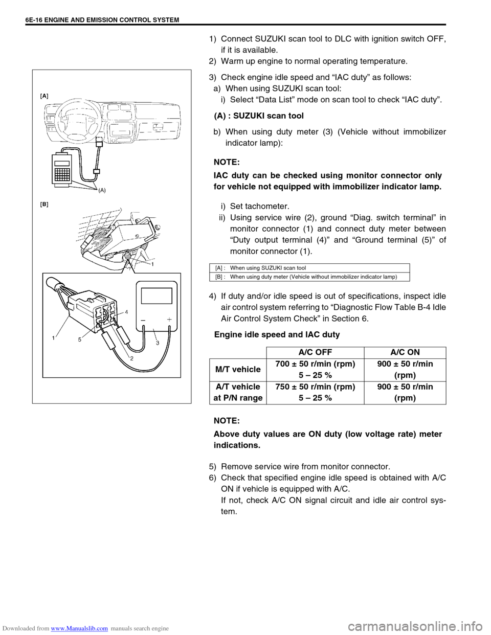
3) Check engine idle speed and “IAC duty” as follows:
a) When using SUZUKI scan tool:
i) Select “Data List” mode on scan tool to check “IAC duty”.
(A) : SUZUKI scan tool
b) When using duty meter (3) (Vehicle without immobilizer
indicator lamp):
i) Set tachometer.
ii) Using service wire (2), ground “Diag. switch terminal” in
monitor connector (1) and connect duty meter between
“Duty output terminal (4)” and “Ground terminal (5)” of
monitor connector (1).
4) If duty and/or idle speed is out of specifications, inspect idle
air control system referring to “Diagnostic Flow Table B-4 Idle
Air Control System Check” in Section 6.
Engine idle speed and IAC duty
5) Remove service wire from monitor connector.
6) Check that specified engine idle speed is obtained with A/C
ON if vehicle is equipped with A/C.
If not, check A/C ON signal circuit and idle air control sys-
tem. NOTE:
IAC duty can be checked using monitor connector only
for vehicle not equipped with immobilizer indicator lamp.
[A] : When using SUZUKI scan tool
[B] : When using duty meter (Vehicle without immobilizer indicator lamp)
A/C OFF A/C ON
M/T vehicle700 ± 50 r/min (rpm)
5 – 25 %900 ± 50 r/min
(rpm)
A/T vehicle
at P/N range750 ± 50 r/min (rpm)
5 – 25 %900 ± 50 r/min
(rpm)
NOTE:
Above duty values are ON duty (low voltage rate) meter
indications.
Page 622 of 687
Downloaded from www.Manualslib.com manuals search engine ENGINE AND EMISSION CONTROL SYSTEM 6E-17
Idle mixture inspection / adjustment (vehicle without
heated oxygen sensor)
All vehicles not equipped with heated oxygen sensor are shipped
with their CO % factory adjusted as follows.
Engine idle mixture (CO %)
0.5 – 1.5 % at specified idle speed
Idle mixture adjustment should never be changed from the origi-
nal factory setting. However, if during diagnosis, the check indi-
cates idle mixture to be the cause of a driver performance
complaint or emission failure, the idle mixture can be adjusted
using the following procedures.
1) Check idle speed according to “Idle Speed / Idle Air Control
(IAC) Duty Inspection” in this section.
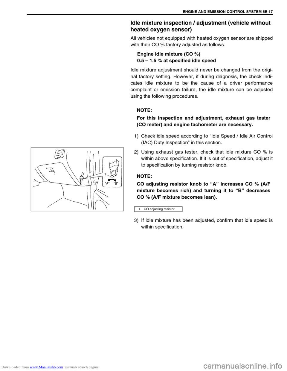
2) Using exhaust gas tester, check that idle mixture CO % is
within above specification. If it is out of specification, adjust it
to specification by turning resistor knob.
3) If idle mixture has been adjusted, confirm that idle speed is
within specification. NOTE:
For this inspection and adjustment, exhaust gas tester
(CO meter) and engine tachometer are necessary.
NOTE:
CO adjusting resistor knob to “A” increases CO % (A/F
mixture becomes rich) and turning it to “B” decreases
CO % (A/F mixture becomes lean).
1. CO adjusting resistor
Page 627 of 687

Downloaded from www.Manualslib.com manuals search engine 6E-22 ENGINE AND EMISSION CONTROL SYSTEM
Fuel Delivery System
Fuel pressure inspection
1) Relieve fuel pressure in fuel feed line referring to “Fuel Pres-
sure Relief Procedure” in Section 6.
2) Disconnect fuel feed hose from fuel delivery pipe.
3) Connect special tools and hose between fuel delivery pipe
(1) and fuel feed hose (2) as shown in figure, and clamp
hoses securely to ensure no leaks occur during checking.
Special tool
(A) : 09912-58442
(B) : 09912-58432
(C) : 09912-58490
4) Check that battery voltage is above 11 V.
5) Turn ignition switch ON to operate fuel pump and after 2 sec-
onds turn it OFF. Repeat this 3 or 4 times and then check
fuel pressure.
Fuel pressure specification WARNING:
Be sure to perform work in a well-ventilated area and
away from any open flames, or there is a risk of a fire
breaking out.
CAUTION:
A small amount of fuel may be released when fuel hose is
disconnected. Place container under the joint with a
shop cloth so that released fuel is caught in container or
absorbed in cloth. Place that cloth in an approved con-
tainer.
3. Fuel return pipe
CONDITION FUEL PRESSURE
With fuel pump operating and
engine stopped270 – 310 kPa
2.7 – 3.1 kg/cm
2,
38.4 – 44.0 psi
At specified idle speed 210 – 260 kPa
2.1 – 2.6 kg/cm
2,
29.8 – 37.0 psi
With 1 min. after engine (fuel
pump) stop (Pressure
reduces as time passes)over 200 kPa
2.0 kg/cm
2, 28.4 psi
Page 630 of 687
Downloaded from www.Manualslib.com manuals search engine ENGINE AND EMISSION CONTROL SYSTEM 6E-25
INSTALLATION
For installation, reverse removal procedure and note following
precautions.
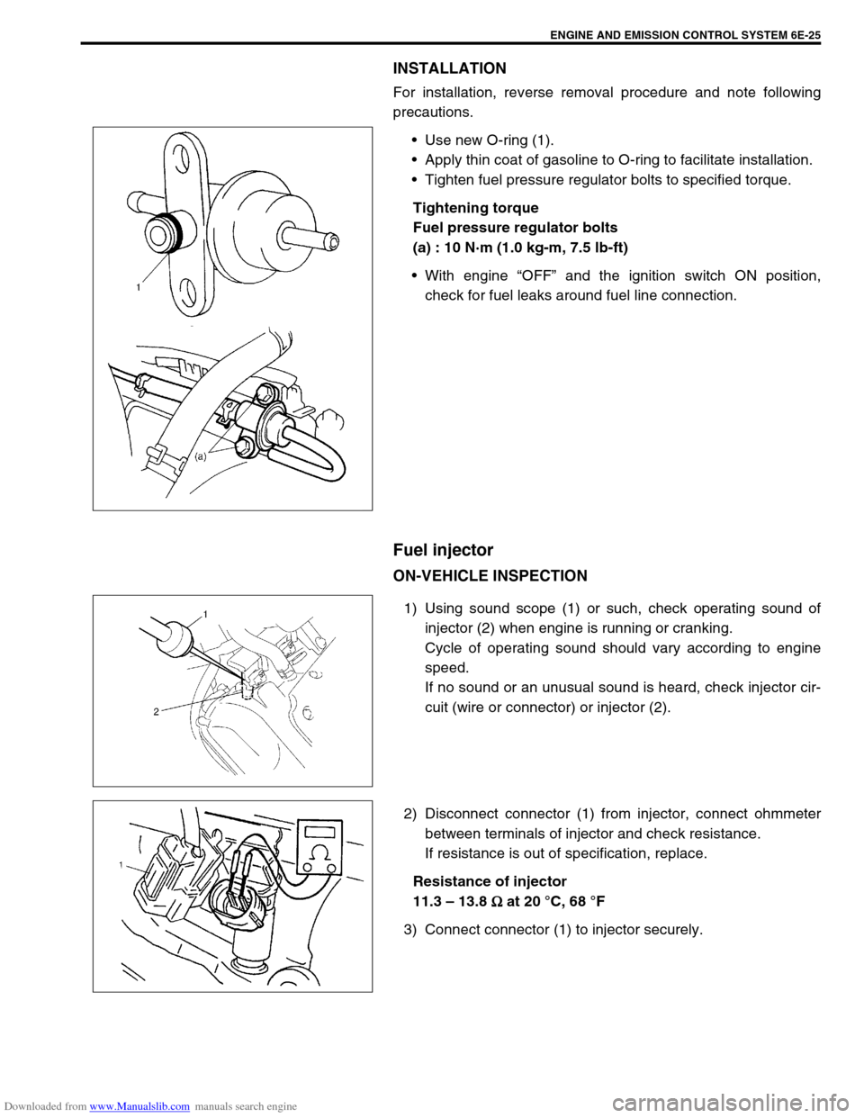
Use new O-ring (1).
Apply thin coat of gasoline to O-ring to facilitate installation.
Tighten fuel pressure regulator bolts to specified torque.
Tightening torque
Fuel pressure regulator bolts
(a) : 10 N·m (1.0 kg-m, 7.5 lb-ft)
With engine “OFF” and the ignition switch ON position,
check for fuel leaks around fuel line connection.
Fuel injector
ON-VEHICLE INSPECTION
1) Using sound scope (1) or such, check operating sound of
injector (2) when engine is running or cranking.
Cycle of operating sound should vary according to engine
speed.
If no sound or an unusual sound is heard, check injector cir-
cuit (wire or connector) or injector (2).
2) Disconnect connector (1) from injector, connect ohmmeter
between terminals of injector and check resistance.
If resistance is out of specification, replace.
Resistance of injector
11.3 – 13.8
Ω
ΩΩ Ω at 20 °C, 68 °F
3) Connect connector (1) to injector securely.
Page 641 of 687

Downloaded from www.Manualslib.com manuals search engine 6E-36 ENGINE AND EMISSION CONTROL SYSTEM
Vehicle speed sensor (VSS)
INSPECTION
Check vehicle speed sensor referring to step 7 of “DTC P0500
(No.16) Flow Table” in Section 6. If malfunction is found, replace.
Fuel level sensor (GAUGE)
INSPECTION
Refer to “Fuel Meter / Fuel Gauge Unit” in Section 8.
REMOVAL / INSTALLATION
Refer to “Fuel Pump Assembly” in Section 6C.
Knock sensor
INSPECTION
Check knock sensor referring to “DTC P0325 (No.17) Flow Table”
in Section 6. If malfunction is found, replace.
REMOVAL / INSTALLATION
Refer to “Knock Sensor” in Section 6A1.
Main relay, fuel pump relay and A/C condenser fan
control relay
INSPECTION
1) Disconnect negative cable at battery.
2) Remove main relay (1), fuel pump relay (2) and A/C con-
denser fan control relay (3) from vehicle.
3) Check that there is no continuity between terminal “A” and
“B”. If there is continuity, replace relay.
4) Connect battery positive (+) terminal to terminal “C” of relay.
Connect battery negative (–) terminal “D” of relay.
Check continuity between terminal “A” and “B”.
If there is no continuity when relay is connected to the bat-
tery, replace relay.
Page 642 of 687
Downloaded from www.Manualslib.com manuals search engine ENGINE AND EMISSION CONTROL SYSTEM 6E-37
Fuel cut operation
INSPECTION
1) Warm up engine to normal operating temperature.
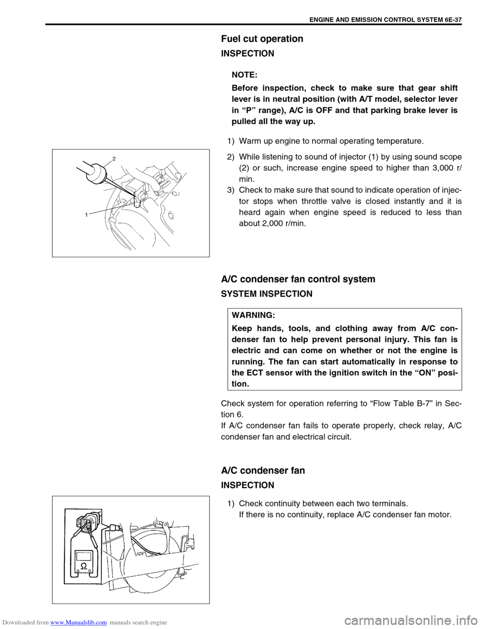
2) While listening to sound of injector (1) by using sound scope
(2) or such, increase engine speed to higher than 3,000 r/
min.
3) Check to make sure that sound to indicate operation of injec-
tor stops when throttle valve is closed instantly and it is
heard again when engine speed is reduced to less than
about 2,000 r/min.
A/C condenser fan control system
SYSTEM INSPECTION
Check system for operation referring to “Flow Table B-7” in Sec-
tion 6.
If A/C condenser fan fails to operate properly, check relay, A/C
condenser fan and electrical circuit.
A/C condenser fan
INSPECTION
1) Check continuity between each two terminals.
If there is no continuity, replace A/C condenser fan motor. NOTE:
Before inspection, check to make sure that gear shift
lever is in neutral position (with A/T model, selector lever
in “P” range), A/C is OFF and that parking brake lever is
pulled all the way up.
WARNING:
Keep hands, tools, and clothing away from A/C con-
denser fan to help prevent personal injury. This fan is
electric and can come on whether or not the engine is
running. The fan can start automatically in response to
the ECT sensor with the ignition switch in the “ON” posi-
tion.
Page 643 of 687
Downloaded from www.Manualslib.com manuals search engine 6E-38 ENGINE AND EMISSION CONTROL SYSTEM
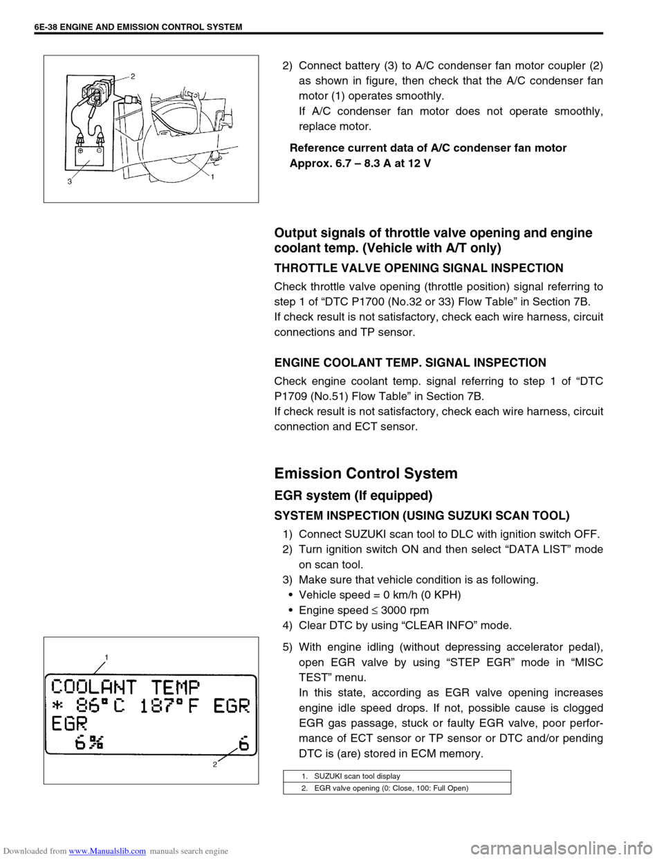
2) Connect battery (3) to A/C condenser fan motor coupler (2)
as shown in figure, then check that the A/C condenser fan
motor (1) operates smoothly.
If A/C condenser fan motor does not operate smoothly,
replace motor.
Reference current data of A/C condenser fan motor
Approx. 6.7 – 8.3 A at 12 V
Output signals of throttle valve opening and engine
coolant temp. (Vehicle with A/T only)
THROTTLE VALVE OPENING SIGNAL INSPECTION
Check throttle valve opening (throttle position) signal referring to
step 1 of “DTC P1700 (No.32 or 33) Flow Table” in Section 7B.
If check result is not satisfactory, check each wire harness, circuit
connections and TP sensor.
ENGINE COOLANT TEMP. SIGNAL INSPECTION
Check engine coolant temp. signal referring to step 1 of “DTC
P1709 (No.51) Flow Table” in Section 7B.
If check result is not satisfactory, check each wire harness, circuit
connection and ECT sensor.
Emission Control System
EGR system (If equipped)
SYSTEM INSPECTION (USING SUZUKI SCAN TOOL)
1) Connect SUZUKI scan tool to DLC with ignition switch OFF.
2) Turn ignition switch ON and then select “DATA LIST” mode
on scan tool.
3) Make sure that vehicle condition is as following.
Vehicle speed = 0 km/h (0 KPH)
Engine speed ≤ 3000 rpm
4) Clear DTC by using “CLEAR INFO” mode.
5) With engine idling (without depressing accelerator pedal),
open EGR valve by using “STEP EGR” mode in “MISC
TEST” menu.
In this state, according as EGR valve opening increases
engine idle speed drops. If not, possible cause is clogged
EGR gas passage, stuck or faulty EGR valve, poor perfor-
mance of ECT sensor or TP sensor or DTC and/or pending
DTC is (are) stored in ECM memory.
1. SUZUKI scan tool display
2. EGR valve opening (0: Close, 100: Full Open)