2005 SUZUKI JIMNY Speed
[x] Cancel search: SpeedPage 645 of 687

Downloaded from www.Manualslib.com manuals search engine 6E-40 ENGINE AND EMISSION CONTROL SYSTEM
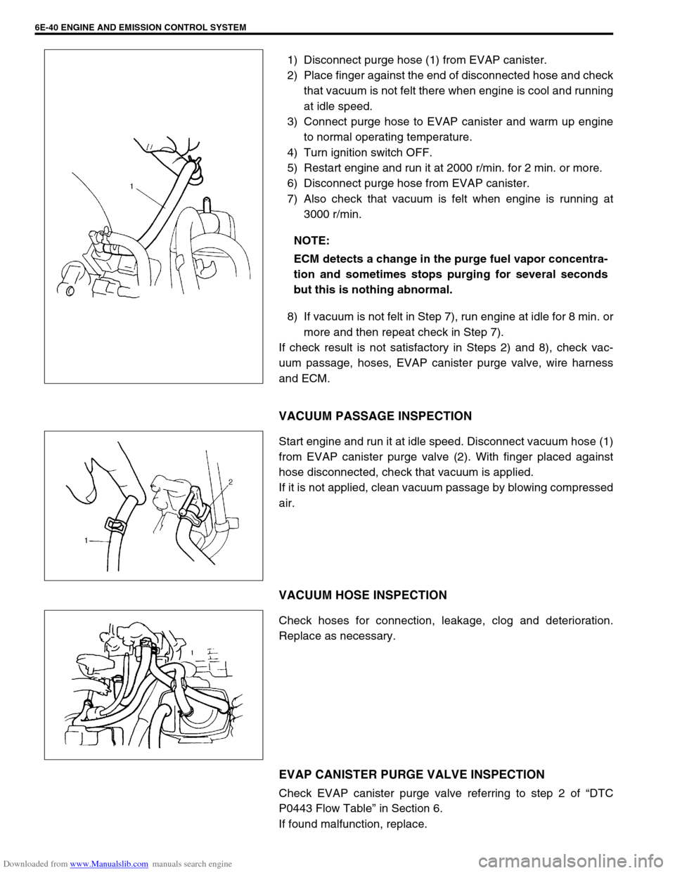
1) Disconnect purge hose (1) from EVAP canister.
2) Place finger against the end of disconnected hose and check
that vacuum is not felt there when engine is cool and running
at idle speed.
3) Connect purge hose to EVAP canister and warm up engine
to normal operating temperature.
4) Turn ignition switch OFF.
5) Restart engine and run it at 2000 r/min. for 2 min. or more.
6) Disconnect purge hose from EVAP canister.
7) Also check that vacuum is felt when engine is running at
3000 r/min.
8) If vacuum is not felt in Step 7), run engine at idle for 8 min. or
more and then repeat check in Step 7).
If check result is not satisfactory in Steps 2) and 8), check vac-
uum passage, hoses, EVAP canister purge valve, wire harness
and ECM.
VACUUM PASSAGE INSPECTION
Start engine and run it at idle speed. Disconnect vacuum hose (1)
from EVAP canister purge valve (2). With finger placed against
hose disconnected, check that vacuum is applied.
If it is not applied, clean vacuum passage by blowing compressed
air.
VACUUM HOSE INSPECTION
Check hoses for connection, leakage, clog and deterioration.
Replace as necessary.
EVAP CANISTER PURGE VALVE INSPECTION
Check EVAP canister purge valve referring to step 2 of “DTC
P0443 Flow Table” in Section 6.
If found malfunction, replace.NOTE:
ECM detects a change in the purge fuel vapor concentra-
tion and sometimes stops purging for several seconds
but this is nothing abnormal.
Page 657 of 687

Downloaded from www.Manualslib.com manuals search engine 6F-8 IGNITION SYSTEM (ELECTRONIC IGNITION SYSTEM)
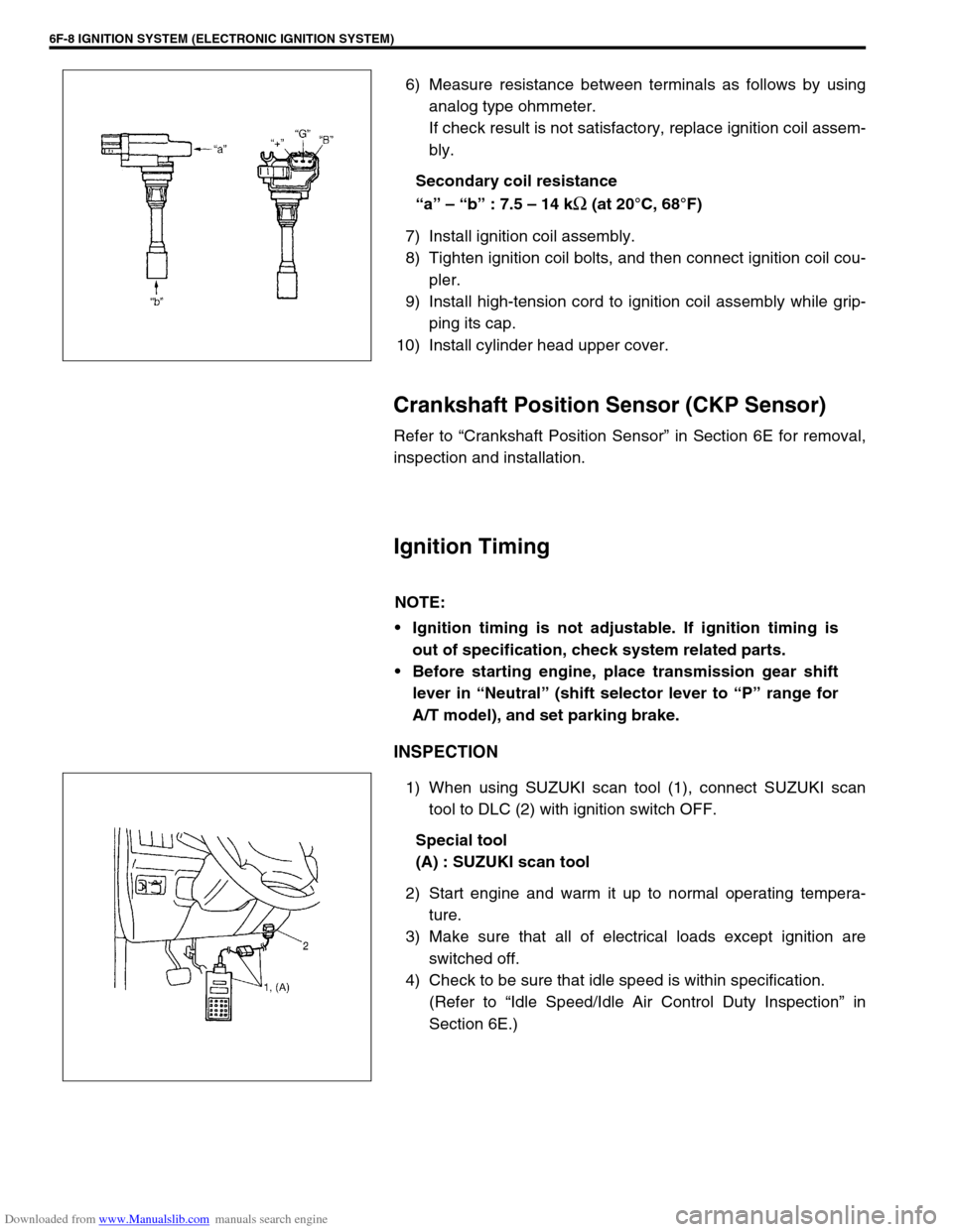
6) Measure resistance between terminals as follows by using
analog type ohmmeter.
If check result is not satisfactory, replace ignition coil assem-
bly.
Secondary coil resistance
“a” – “b” : 7.5 – 14 k
Ω (at 20°C, 68°F)
7) Install ignition coil assembly.
8) Tighten ignition coil bolts, and then connect ignition coil cou-
pler.
9) Install high-tension cord to ignition coil assembly while grip-
ping its cap.
10) Install cylinder head upper cover.
Crankshaft Position Sensor (CKP Sensor)
Refer to “Crankshaft Position Sensor” in Section 6E for removal,
inspection and installation.
Ignition Timing
INSPECTION
1) When using SUZUKI scan tool (1), connect SUZUKI scan
tool to DLC (2) with ignition switch OFF.
Special tool
(A) : SUZUKI scan tool
2) Start engine and warm it up to normal operating tempera-
ture.
3) Make sure that all of electrical loads except ignition are
switched off.
4) Check to be sure that idle speed is within specification.
(Refer to “Idle Speed/Idle Air Control Duty Inspection” in
Section 6E.)
NOTE:
Ignition timing is not adjustable. If ignition timing is
out of specification, check system related parts.
Before starting engine, place transmission gear shift
lever in “Neutral” (shift selector lever to “P” range for
A/T model), and set parking brake.
Page 658 of 687

Downloaded from www.Manualslib.com manuals search engine IGNITION SYSTEM (ELECTRONIC IGNITION SYSTEM 6F-9
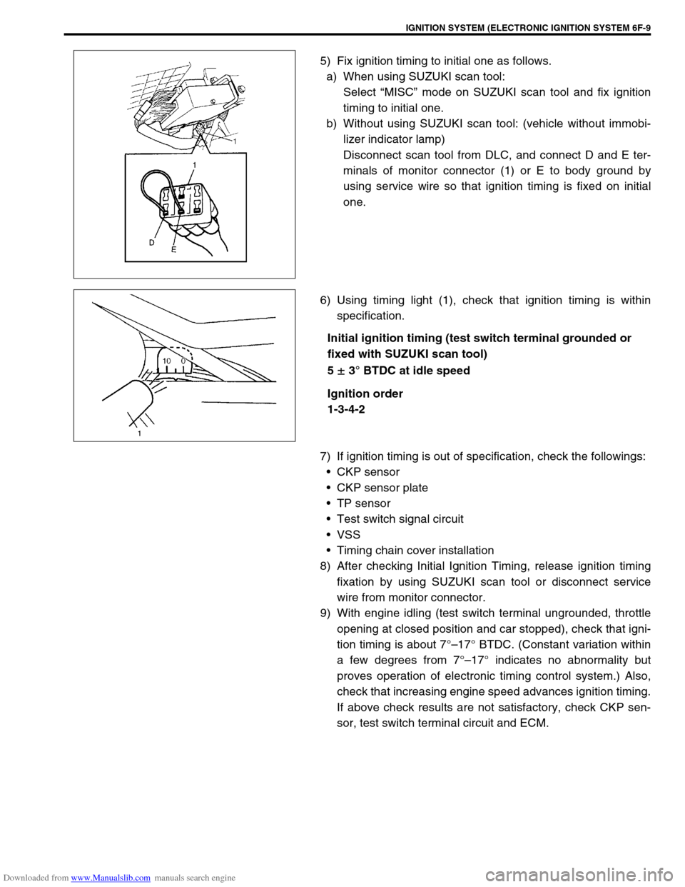
5) Fix ignition timing to initial one as follows.
a) When using SUZUKI scan tool:
Select “MISC” mode on SUZUKI scan tool and fix ignition
timing to initial one.
b) Without using SUZUKI scan tool: (vehicle without immobi-
lizer indicator lamp)
Disconnect scan tool from DLC, and connect D and E ter-
minals of monitor connector (1) or E to body ground by
using service wire so that ignition timing is fixed on initial
one.
6) Using timing light (1), check that ignition timing is within
specification.
Initial ignition timing (test switch terminal grounded or
fixed with SUZUKI scan tool)
5
± 3° BTDC at idle speed
Ignition order
1-3-4-2
7) If ignition timing is out of specification, check the followings:
CKP sensor
CKP sensor plate
TP sensor
Test switch signal circuit
VSS
Timing chain cover installation
8) After checking Initial Ignition Timing, release ignition timing
fixation by using SUZUKI scan tool or disconnect service
wire from monitor connector.
9) With engine idling (test switch terminal ungrounded, throttle
opening at closed position and car stopped), check that igni-
tion timing is about 7°–17° BTDC. (Constant variation within
a few degrees from 7°–17° indicates no abnormality but
proves operation of electronic timing control system.) Also,
check that increasing engine speed advances ignition timing.
If above check results are not satisfactory, check CKP sen-
sor, test switch terminal circuit and ECM.
Page 671 of 687

Downloaded from www.Manualslib.com manuals search engine 6H-4 CHARGING SYSTEM
When keeping battery on vehicle over a long period of time, follow
instructions given below.
Weekly, start the engine and run it until it reaches normal
operating temperature with engine speed of 2,000 to 3,000
rpm. Make sure all electric switches are off before storing the
vehicle.
Recharge the battery twice a month to prevent it from dis-
charging excessively. This is especially important when
ambient temperature is low.
The battery discharges even when it is not used, while vehi-
cles are being stored. Battery electrolyte can freeze and bat-
tery case can crack at cold ambient condition if battery is not
properly charged.
2) Keep the battery cable connections clean.
The cable connections, particularly at the positive (+) termi-
nal post, tend to become corroded. The product of corrosion,
or rust, on the mating faces of conductors resists the flow of
current.
Clean the terminals and fittings periodically to ensure good
metal-to-metal contact, and grease the connections after
each cleaning to protect them against rusting.
3) Be always in the know as to the state of charge of the bat-
tery. The simplest way to tell the state of charge is to carry
out a hydrometer test. The hydrometer is an instrument for
measuring the specific gravity (S.G.) of the battery electro-
lyte. The S.G. of the electrolyte is indicative of the state of
charge. Refer to “HYDROMETER TEST” in this section.
Generator
The generator is a small and high performance type with an IC regulator incorporated.
The internal components are connected electrically as shown below figure.
The generator features are as follows:
Solid state regulator is mounted inside the generator.
All regulator components are enclosed into a solid mold.
This unit along with the brush holder assembly is attached to the rear housing.
The IC regulator uses integrated circuits and controls the voltage produced by the generator, and the volt-
age setting cannot be adjusted.
The generator rotor bearings contain enough grease to eliminate the need for periodic lubrication. Two
brushes carry current through the two slip rings to the field coil mounted on the rotor, and under normal con-
ditions will provide long period of attention-free service.
The stator windings are assembled on the inside of a laminated core that forms part of the generator frame.
A condenser mounted in the rear housing suppresses radio noise.
Page 673 of 687

Downloaded from www.Manualslib.com manuals search engine 6H-6 CHARGING SYSTEM
Diagnosis
Battery
COMMON CAUSES OF FAILURE
A battery is not designed to last indefinitely; however, with proper
care, it will provide many years of service. If the battery performs
satisfactorily during test but fails to operate properly for no appar-
ent reason, the followings are some factors that may point to the
cause of trouble:
Accessories left on overnight or for an extended period with-
out the generator operating.
Slow average driving speeds for short periods.
Electrical load exceeding generator output particularly with
addition of after market equipment.
Defects in charging system such as high resistance, slipping
drive belt, loose generator output terminal, faulty generator
or voltage regulator. Refer to “Generator” in this “Diagnosis”
section.
Battery abuse, including failure to keep battery cable termi-
nals clean and tight or loose battery hold down.
Mechanical problems in electrical system such as shorted or
pinched wires.
VISUAL INSPECTION
Check for obvious damage, such as cracked or broken case or
cover, that could permit loss of electrolyte. If obvious damage is
noted, replace battery. Determine cause of damage and correct
as needed.
HYDROMETER TEST
The direct method of checking the battery for state of charge is to
carry out a high rate discharge test, which involves a special pre-
cise voltmeter and an expensive instrument used in the service
shops, but not recommendable to the user of the vehicle.
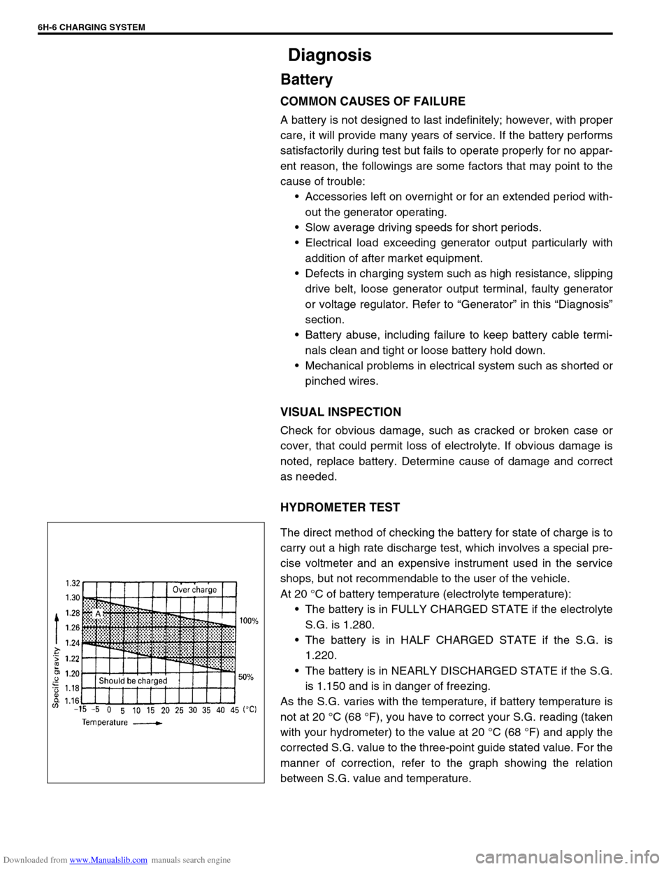
At 20 °C of battery temperature (electrolyte temperature):
The battery is in FULLY CHARGED STATE if the electrolyte
S.G. is 1.280.
The battery is in HALF CHARGED STATE if the S.G. is
1.220.
The battery is in NEARLY DISCHARGED STATE if the S.G.
is 1.150 and is in danger of freezing.
As the S.G. varies with the temperature, if battery temperature is
not at 20 °C (68 °F), you have to correct your S.G. reading (taken
with your hydrometer) to the value at 20 °C (68 °F) and apply the
corrected S.G. value to the three-point guide stated value. For the
manner of correction, refer to the graph showing the relation
between S.G. value and temperature.
Page 675 of 687

Downloaded from www.Manualslib.com manuals search engine 6H-8 CHARGING SYSTEM
UNDERCHARGED BATTERY
This condition, as evidenced by slow cranking or indicator clear
with red dot can be caused by one or more of the following condi-
tions even though indicator lamp may be operating normal.
Following procedure also applies to cars with voltmeter and
ammeter.
1) Make sure that undercharged condition has not been caused
by accessories left on for extended period of time.
2) Check drive belt for proper tension.
3) If battery defect is suspected, refer to BATTERY section.
4) Inspect wiring for defects. Check all connections for tight-
ness and cleanliness, battery cable connections at battery,
starting motor and ignition ground cable.
5) Connect voltmeter and ammeter as shown in the figure.
6) Measure current and voltage.
No-load Check
1) Run engine from idling up to 2,000 rpm and read meters.
Standard current
10 A maximum
Standard voltage
14.4 – 15.0 V (at 20 °C, 68 °F)
Higher Voltage
If voltage is higher than standard value, check ground of brushes.
If brushes are not grounded, replace IC regulator.
Lower Voltage
If voltage is below or in standard value, increase engine speed up
to 2,000 – 2,500 rpm soon after starting engine, and read maxi-
mum value on ammeter immediately.
If current is less than 49 A, repair or replace generator.NOTE:
Use fully charged battery.
1. Generator
2. Ammeter (between generator (B) terminal and battery (+) terminal)
3. Voltmeter (between generator (B) terminal and ground)
4. Battery
5. Load
6. Switch
NOTE:
Turn off switches of all accessories (wiper, heater etc.).
NOTE:
Consideration should be taken that voltage will differ
somewhat with regulator case temperature as shown in
the graph.
Page 684 of 687

Downloaded from www.Manualslib.com manuals search engine CHARGING SYSTEM 6H-17
Specifications
Battery
55B24R TYPE
38B20R TYPE
Generator
Tightening Torque Specification
Rated capacity 36 AH/5HR, 12 Volts
Electrolyte 3.1 L (6.55/5.46 US/lmp pt)
Electrolyte S.G. 1.28 when fully charged at 20 °C (68 °F)
Rated capacity 28 AH/5HR, 12 Volts
Electrolyte 2.1 L (4.44/3.70 US/lmp pt)
Electrolyte S.G. 1.28 when fully charged at 20 °C (68 °F)
Type 70 A type
Rated voltage 12 V
Nominal output 70 A
Permissible max. speed 18,000 r/min.
No-load speed 1,300 r/min (rpm)
Setting voltage 14.4 to 15.0 V
Permissible ambient temperature–30 to 90 °C (–22 to 194 °F)
Polarity Negative ground
Rotation Clockwise viewed from pulley side
Fastening partTightening torque
Nm kg-m lb-ft
Body ground bolt 8 0.8 6.0
Generator mounting bolts 23 2.3 16.5
“B” terminal inner nut 4.2 0.42 3.0
“B” terminal outer nut 8 0.8 6.0
Pulley nut 118 11.8 85.5
Rear end frame nuts
4.50.453.5
Rear end cover nuts
Rectifier “B” bolt 3.9 0.39 3.0
Stator stud bolts 8.8 0.88 6.5
Drive end bearing plate screws 2.6 0.26 2.0
Rectifier screws
2.00.201.5
Regulator and brush holder screws
Terminal plate bolt 3.8 0.38 3.0