2005 SUZUKI JIMNY Engine Mechanical
[x] Cancel search: Engine MechanicalPage 572 of 687
Downloaded from www.Manualslib.com manuals search engine ENGINE MECHANICAL (M13 ENGINE) 6A1-91
5) Install crankshaft to cylinder block.
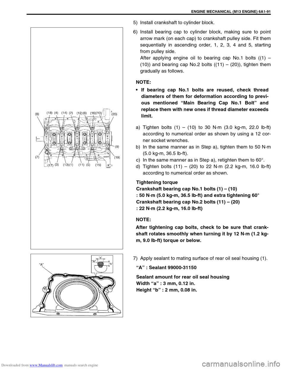
6) Install bearing cap to cylinder block, making sure to point
arrow mark (on each cap) to crankshaft pulley side. Fit them
sequentially in ascending order, 1, 2, 3, 4 and 5, starting
from pulley side.
After applying engine oil to bearing cap No.1 bolts ((1) –
(10)) and bearing cap No.2 bolts ((11) – (20)), tighten them
gradually as follows.
a) Tighten bolts (1) – (10) to 30 N·m (3.0 kg-m, 22.0 lb-ft)
according to numerical order as shown by using a 12 cor-
ner socket wrenches.
b) In the same manner as in Step a), tighten them to 50 N·m
(5.0 kg-m, 36.5 lb-ft).
c) In the same manner as in Step a), retighten them to 60°.
d) Tighten bolts (11) – (20) to 22 N·m (2.2 kg-m, 16.0 lb-ft)
according to numerical order as shown.
Tightening torque
Crankshaft bearing cap No.1 bolts (1) – (10)
: 50 N·m (5.0 kg-m, 36.5 lb-ft) and extra tightening 60°
Crankshaft bearing cap No.2 bolts (11) – (20)
: 22 N·m (2.2 kg-m, 16.0 lb-ft)
7) Apply sealant to mating surface of rear oil seal housing (1).
“A” : Sealant 99000-31150
Sealant amount for rear oil seal housing
Width “a” : 3 mm, 0.12 in.
Height “b” : 2 mm, 0.08 in. NOTE:
If bearing cap No.1 bolts are reused, check thread
diameters of them for deformation according to previ-
ous mentioned “Main Bearing Cap No.1 Bolt” and
replace them with new ones if thread diameter exceeds
limit.
NOTE:
After tightening cap bolts, check to be sure that crank-
shaft rotates smoothly when turning it by 12 N·m (1.2 kg-
m, 9.0 lb-ft) torque or below.
Page 573 of 687
Downloaded from www.Manualslib.com manuals search engine 6A1-92 ENGINE MECHANICAL (M13 ENGINE)
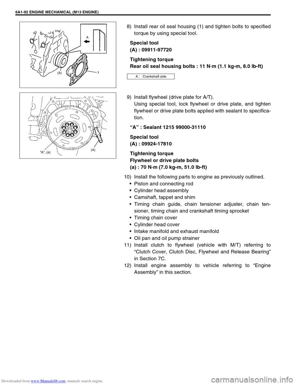
8) Install rear oil seal housing (1) and tighten bolts to specified
torque by using special tool.
Special tool
(A) : 09911-97720
Tightening torque
Rear oil seal housing bolts : 11 N·m (1.1 kg-m, 8.0 lb-ft)
9) Install flywheel (drive plate for A/T).
Using special tool, lock flywheel or drive plate, and tighten
flywheel or drive plate bolts applied with sealant to specifica-
tion.
“A” : Sealant 1215 99000-31110
Special tool
(A) : 09924-17810
Tightening torque
Flywheel or drive plate bolts
(a) : 70 N·m (7.0 kg-m, 51.0 lb-ft)
10) Install the following parts to engine as previously outlined.
Piston and connecting rod
Cylinder head assembly
Camshaft, tappet and shim
Timing chain guide, chain tensioner adjuster, chain ten-
sioner, timing chain and crankshaft timing sprocket
Timing chain cover
Cylinder head cover
Intake manifold and exhaust manifold
Oil pan and oil pump strainer
11) Install clutch to flywheel (vehicle with M/T) referring to
“Clutch Cover, Clutch Disc, Flywheel and Release Bearing”
in Section 7C.
12) Install engine assembly to vehicle referring to “Engine
Assembly” in this section.
A : Crankshaft side
Page 574 of 687

Downloaded from www.Manualslib.com manuals search engine ENGINE MECHANICAL (M13 ENGINE) 6A1-93
Required Service Material
Tightening Torque Specification
MaterialRecommended SUZUKI product
(Part Number)Use
Sealant SUZUKI BOND NO. 1207C
(99000-31150)To apply to mating surface of cylinder block and oil
pan.
To apply to mating surface of cylinder block and
timing chain cover.
To apply to sealing surface of cylinder head cover.
To apply to mating surface to rear oil seal housing.
SUZUKI BOND NO. 1207B
(99000-31140)To apply to mating surface of cylinder block, cylin-
der head and timing chain cover.
SUZUKI BOND NO. 1215
(99000-31110)To flywheel (M/T) or drive plate (A/T) bolts.
Fastening partTightening torque
Nm kg-m lb-ft
Oil pressure switch 14.0 1.4 10.5
Camshaft housing bolts
(for replacement of shim)8.0 0.8 6.0
Camshaft housing bolts 11.0 1.1 8.0
Cylinder head cover bolts 8.0 0.8 6.0
Intake manifold bolts and nuts 25.0 2.5 18.0
Exhaust manifold bolts and nuts 55.0 5.5 40.0
Exhaust pipe bolts 50.0 5.0 36.5
Exhaust manifold stiffener bolts 50.0 5.0 36.5
Oil pump strainer bolt 11.0 1.1 8.0
Oil pump strainer bracket bolt 11.0 1.1 8.0
Oil pan bolts and nuts 11.0 1.1 8.0
Oil pan drain plug 50.0 5.0 36.5
Timing chain cover bolts and nut 23.0 2.3 17.0
Crankshaft pulley bolt 150.0 15.0 108.5
Oil pump rotor plate bolts 11.0 1.1 8.0
Timing chain No.1 guide bolts 9.0 0.9 6.5
Timing chain tensioner adjuster bolts 11.0 1.1 8.0
Venturi plug 5.0 0.5 3.5
Cylinder head bolt for M8 22.0 2.2 16.0
Cylinder head bolts for M10 a) Tighten 40 N·m
b) Turn 60°
c) Turn 60°a) Tighten 4.0 kg-m
b) Turn 60°
c) Turn 60°a) Tighten 29.0 lb-ft
b) Turn 60°
c) Turn 60°
Connecting rod bearing cap nuts a) Tighten 15 N·m
b) Turn 45°
c) Turn 45°a) Tighten 1.5 kg-m
b) Turn 45°
c) Turn 45°a) Tighten 11.0 lb-ft
b) Turn 45°
c) Turn 45°
Engine mounting bolts 50.0 5.0 36.5
Page 575 of 687
Downloaded from www.Manualslib.com manuals search engine 6A1-94 ENGINE MECHANICAL (M13 ENGINE)
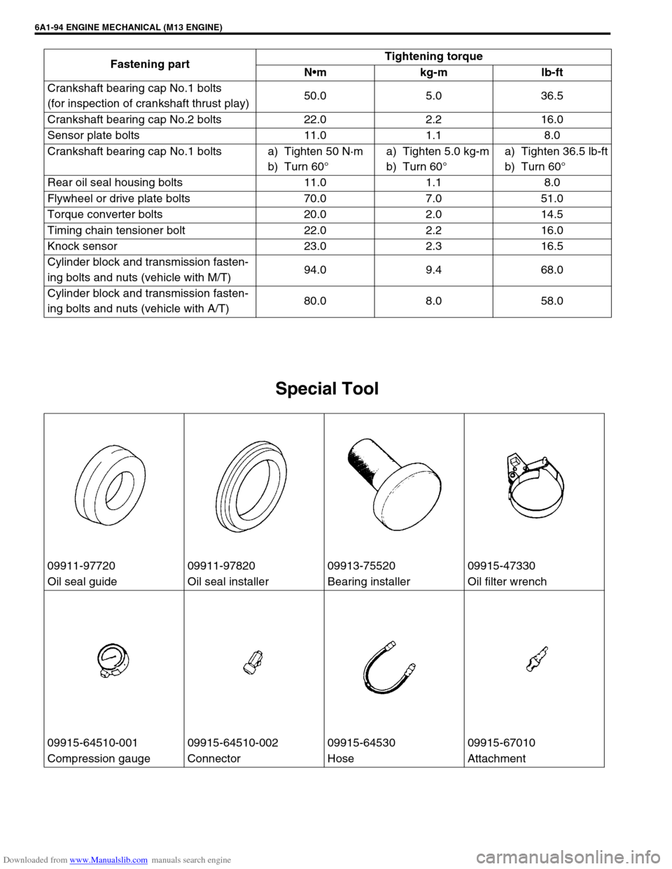
Special Tool
Crankshaft bearing cap No.1 bolts
(for inspection of crankshaft thrust play)50.0 5.0 36.5
Crankshaft bearing cap No.2 bolts 22.0 2.2 16.0
Sensor plate bolts 11.0 1.1 8.0
Crankshaft bearing cap No.1 bolts a) Tighten 50 N·m
b) Turn 60°a) Tighten 5.0 kg-m
b) Turn 60°a) Tighten 36.5 lb-ft
b) Turn 60°
Rear oil seal housing bolts 11.0 1.1 8.0
Flywheel or drive plate bolts 70.0 7.0 51.0
Torque converter bolts 20.0 2.0 14.5
Timing chain tensioner bolt 22.0 2.2 16.0
Knock sensor 23.0 2.3 16.5
Cylinder block and transmission fasten-
ing bolts and nuts (vehicle with M/T)94.0 9.4 68.0
Cylinder block and transmission fasten-
ing bolts and nuts (vehicle with A/T)80.0 8.0 58.0 Fastening partTightening torque
Nm kg-m lb-ft
09911-97720 09911-97820 09913-75520 09915-47330
Oil seal guide Oil seal installer Bearing installer Oil filter wrench
09915-64510-001 09915-64510-002 09915-64530 09915-67010
Compression gauge Connector Hose Attachment
Page 576 of 687

Downloaded from www.Manualslib.com manuals search engine ENGINE MECHANICAL (M13 ENGINE) 6A1-95
09915-67310 09915-77310 09915-78211 09916-14510
Vacuum gauge Oil pressure gauge Oil pressure gauge
attachmentValve lifter
09916-14521 09916-34542 09916-34550 09916-37320
Valve lifter attachment Reamer handle Reamer (5.5 mm) Reamer (10.5 mm)
09916-44910 09916-56011 09916-58210 09916-67020
Valve guide remover Valve guide installer
attachmentValve guide installer han-
dleTappet holder
09916-77310 09916-84511 09917-68221 09917-98221
Piston ring compressor Forceps Camshaft lock holder Valve stem seal installer
Page 577 of 687

Downloaded from www.Manualslib.com manuals search engine 6A1-96 ENGINE MECHANICAL (M13 ENGINE)
09924-17810 09926-58010 09944-36011
Flywheel holder Bearing puller attachment Steering wheel remover
Page 656 of 687
Downloaded from www.Manualslib.com manuals search engine IGNITION SYSTEM (ELECTRONIC IGNITION SYSTEM 6F-7
4) If any abnormality is found, adjust air gap, clean with spark
plug cleaner or replace them with specified new plugs.
For iridium/platinum spark plugs, replace them with new
plugs.
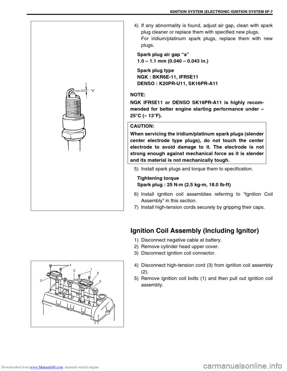
Spark plug air gap “a”
1.0 – 1.1 mm (0.040 – 0.043 in.)
Spark plug type
NGK : BKR6E-11, IFR5E11
DENSO : K20PR-U11, SK16PR-A11
5) Install spark plugs and torque them to specification.
Tightening torque
Spark plug : 25 N·m (2.5 kg-m, 18.0 lb-ft)
6) Install ignition coil assemblies referring to “Ignition Coil
Assembly” in this section.
7) Install high-tension cords securely by gripping their caps.
Ignition Coil Assembly (Including Ignitor)
1) Disconnect negative cable at battery.
2) Remove cylinder head upper cover.
3) Disconnect ignition coil connector.
4) Disconnect high-tension cord (3) from ignition coil assembly
(2).
5) Remove ignition coil bolts (1) and then pull out ignition coil
assembly. NOTE:
NGK IFR5E11 or DENSO SK16PR-A11 is highly recom-
mended for better engine starting performance under –
25°C (– 13°F).
CAUTION:
When servicing the iridium/platinum spark plugs (slender
center electrode type plugs), do not touch the center
electrode to avoid damage to it. The electrode is not
strong enough against mechanical force as it is slender
and its material is not mechanically tough.
Page 673 of 687
Downloaded from www.Manualslib.com manuals search engine 6H-6 CHARGING SYSTEM
Diagnosis
Battery
COMMON CAUSES OF FAILURE
A battery is not designed to last indefinitely; however, with proper
care, it will provide many years of service. If the battery performs
satisfactorily during test but fails to operate properly for no appar-
ent reason, the followings are some factors that may point to the
cause of trouble:
Accessories left on overnight or for an extended period with-
out the generator operating.
Slow average driving speeds for short periods.
Electrical load exceeding generator output particularly with
addition of after market equipment.
Defects in charging system such as high resistance, slipping
drive belt, loose generator output terminal, faulty generator
or voltage regulator. Refer to “Generator” in this “Diagnosis”
section.
Battery abuse, including failure to keep battery cable termi-
nals clean and tight or loose battery hold down.
Mechanical problems in electrical system such as shorted or
pinched wires.
VISUAL INSPECTION
Check for obvious damage, such as cracked or broken case or
cover, that could permit loss of electrolyte. If obvious damage is
noted, replace battery. Determine cause of damage and correct
as needed.
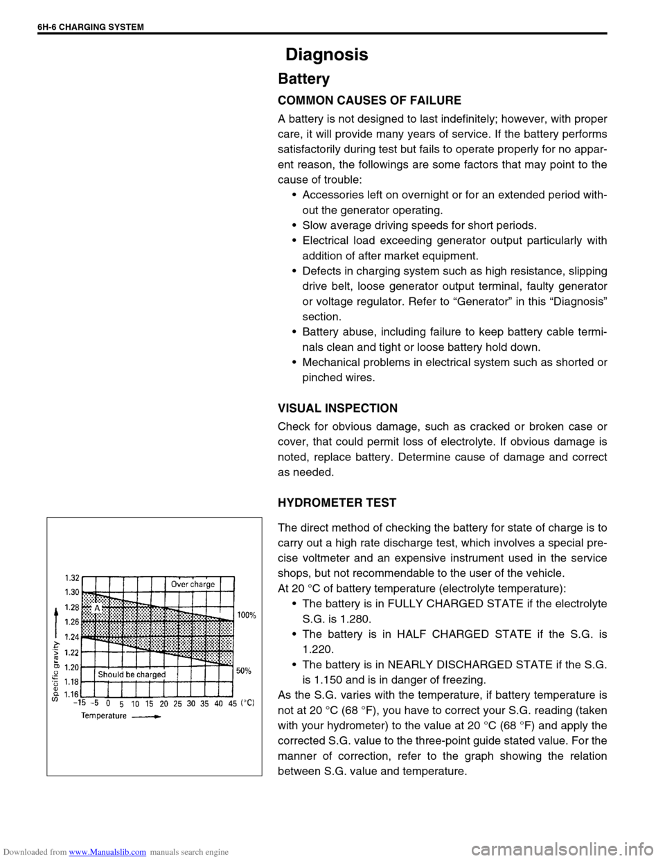
HYDROMETER TEST
The direct method of checking the battery for state of charge is to
carry out a high rate discharge test, which involves a special pre-
cise voltmeter and an expensive instrument used in the service
shops, but not recommendable to the user of the vehicle.
At 20 °C of battery temperature (electrolyte temperature):
The battery is in FULLY CHARGED STATE if the electrolyte
S.G. is 1.280.
The battery is in HALF CHARGED STATE if the S.G. is
1.220.
The battery is in NEARLY DISCHARGED STATE if the S.G.
is 1.150 and is in danger of freezing.
As the S.G. varies with the temperature, if battery temperature is
not at 20 °C (68 °F), you have to correct your S.G. reading (taken
with your hydrometer) to the value at 20 °C (68 °F) and apply the
corrected S.G. value to the three-point guide stated value. For the
manner of correction, refer to the graph showing the relation
between S.G. value and temperature.