2005 SUZUKI JIMNY No start
[x] Cancel search: No startPage 501 of 687

Downloaded from www.Manualslib.com manuals search engine 6A1-20 ENGINE MECHANICAL (M13 ENGINE)
13) Remove intake manifold (1) with throttle body (2) and EGR
pipe (3) from cylinder head (4), and then its gasket.
INSTALLATION
Reverse removal procedure for installation noting the followings.
Use new intake manifold gasket and EGR pipe gasket.
Tighten long bolt (1), short bolt (3) and nuts (2) to specified
torque.
Tightening torque
Intake manifold bolts and nuts
(a) : 25 N·m (2.5 kg-m, 18.0 lb-ft)
Check to ensure that all removed parts are back in place.
Reinstall any necessary parts which have not been rein-
stalled.
Adjust accelerator cable play referring to “Accelerator Cable
Adjustment” in Section 6E.
Refill cooling system referring to “Cooling System Flush and
Refill” in Section 6B.
Upon completion of installation, turn ignition switch ON but
engine OFF and check for fuel leaks.
Finally, start engine and check for engine coolant leaks.
Page 507 of 687
Downloaded from www.Manualslib.com manuals search engine 6A1-26 ENGINE MECHANICAL (M13 ENGINE)
INSTALLATION
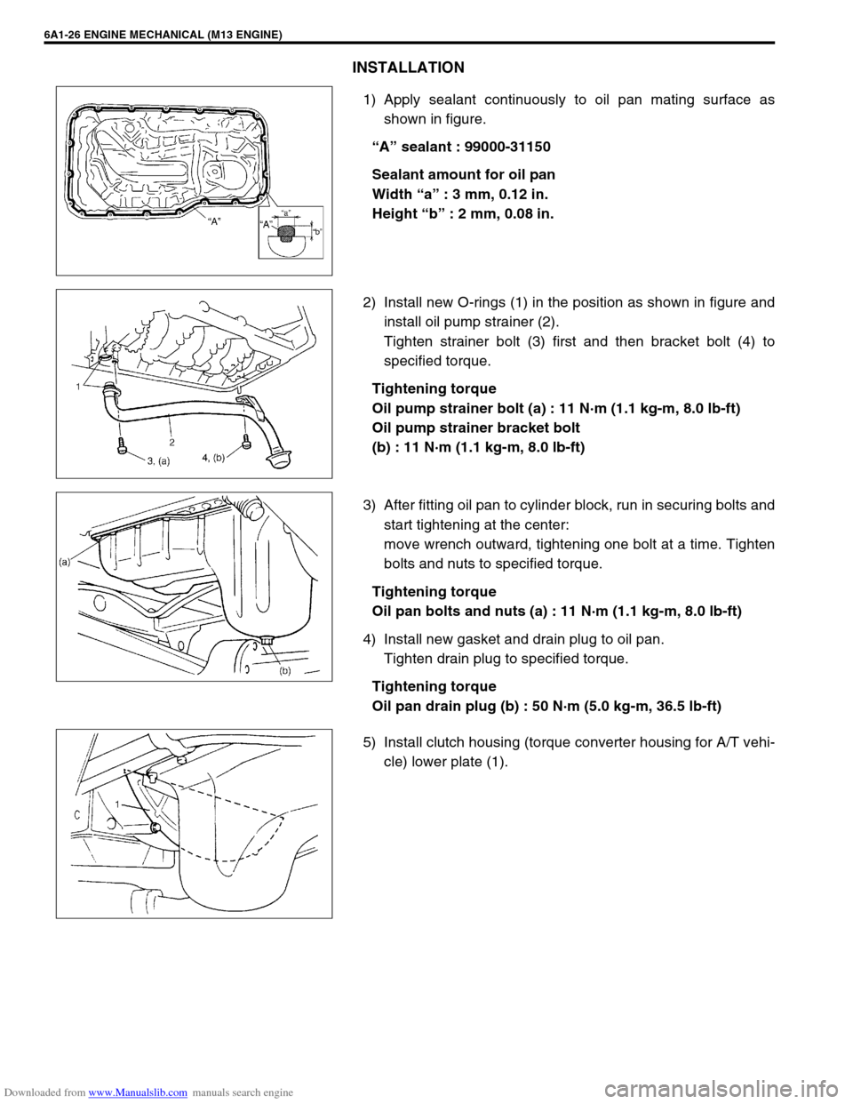
1) Apply sealant continuously to oil pan mating surface as
shown in figure.
“A” sealant : 99000-31150
Sealant amount for oil pan
Width “a” : 3 mm, 0.12 in.
Height “b” : 2 mm, 0.08 in.
2) Install new O-rings (1) in the position as shown in figure and
install oil pump strainer (2).
Tighten strainer bolt (3) first and then bracket bolt (4) to
specified torque.
Tightening torque
Oil pump strainer bolt (a) : 11 N·m (1.1 kg-m, 8.0 lb-ft)
Oil pump strainer bracket bolt
(b) : 11 N·m (1.1 kg-m, 8.0 lb-ft)
3) After fitting oil pan to cylinder block, run in securing bolts and
start tightening at the center:
move wrench outward, tightening one bolt at a time. Tighten
bolts and nuts to specified torque.
Tightening torque
Oil pan bolts and nuts (a) : 11 N·m (1.1 kg-m, 8.0 lb-ft)
4) Install new gasket and drain plug to oil pan.
Tighten drain plug to specified torque.
Tightening torque
Oil pan drain plug (b) : 50 N·m (5.0 kg-m, 36.5 lb-ft)
5) Install clutch housing (torque converter housing for A/T vehi-
cle) lower plate (1).
Page 555 of 687
Downloaded from www.Manualslib.com manuals search engine 6A1-74 ENGINE MECHANICAL (M13 ENGINE)
a) For right hand steering vehicle:
With hose connected, detach A/C compressor from its
bracket.
b) For left hand steering vehicle:
i) Recover refrigerant from refrigeration system using recov-
ery and recycling equipment.
ii) Disconnect magnet clutch lead wire.
iii) Remove suction pipe and disconnect discharge pipe from
A/C compressor.
iv) Remove A/C compressor from its bracket.
When servicing above steps, refer to “Compressor” in Section 1B.
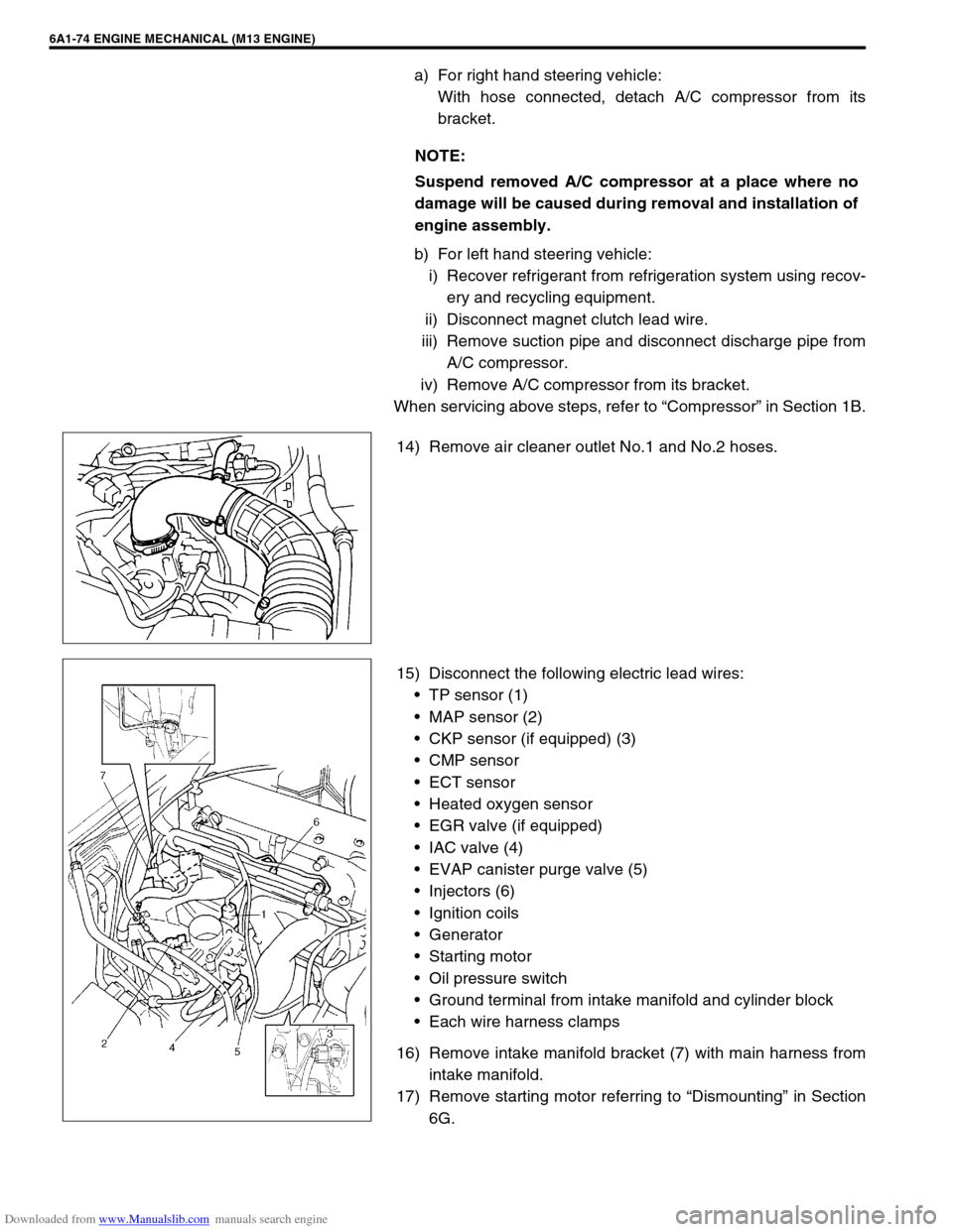
14) Remove air cleaner outlet No.1 and No.2 hoses.
15) Disconnect the following electric lead wires:
TP sensor (1)
MAP sensor (2)
CKP sensor (if equipped) (3)
CMP sensor
ECT sensor
Heated oxygen sensor
EGR valve (if equipped)
IAC valve (4)
EVAP canister purge valve (5)
Injectors (6)
Ignition coils
Generator
Starting motor
Oil pressure switch
Ground terminal from intake manifold and cylinder block
Each wire harness clamps
16) Remove intake manifold bracket (7) with main harness from
intake manifold.
17) Remove starting motor referring to “Dismounting” in Section
6G. NOTE:
Suspend removed A/C compressor at a place where no
damage will be caused during removal and installation of
engine assembly.
Page 572 of 687
Downloaded from www.Manualslib.com manuals search engine ENGINE MECHANICAL (M13 ENGINE) 6A1-91
5) Install crankshaft to cylinder block.
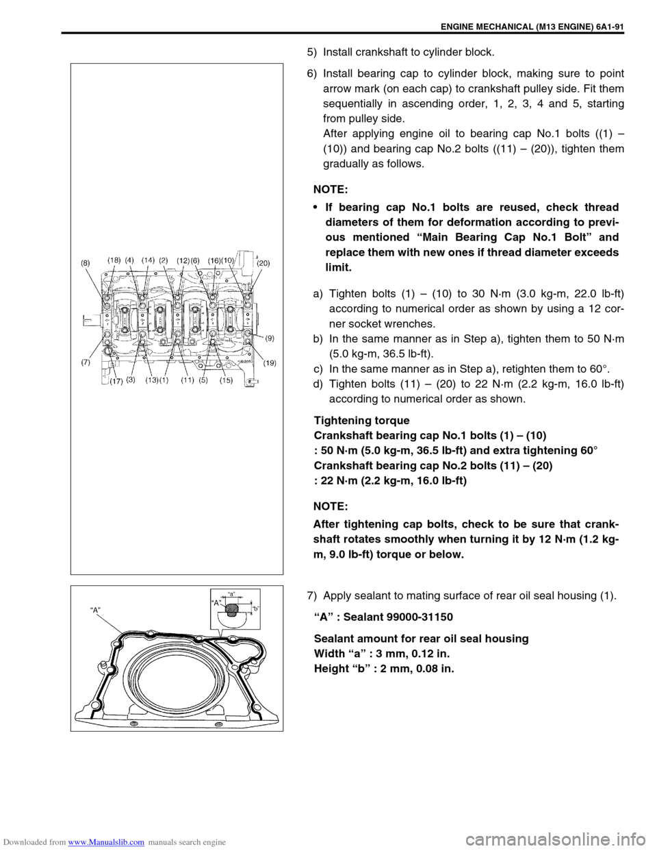
6) Install bearing cap to cylinder block, making sure to point
arrow mark (on each cap) to crankshaft pulley side. Fit them
sequentially in ascending order, 1, 2, 3, 4 and 5, starting
from pulley side.
After applying engine oil to bearing cap No.1 bolts ((1) –
(10)) and bearing cap No.2 bolts ((11) – (20)), tighten them
gradually as follows.
a) Tighten bolts (1) – (10) to 30 N·m (3.0 kg-m, 22.0 lb-ft)
according to numerical order as shown by using a 12 cor-
ner socket wrenches.
b) In the same manner as in Step a), tighten them to 50 N·m
(5.0 kg-m, 36.5 lb-ft).
c) In the same manner as in Step a), retighten them to 60°.
d) Tighten bolts (11) – (20) to 22 N·m (2.2 kg-m, 16.0 lb-ft)
according to numerical order as shown.
Tightening torque
Crankshaft bearing cap No.1 bolts (1) – (10)
: 50 N·m (5.0 kg-m, 36.5 lb-ft) and extra tightening 60°
Crankshaft bearing cap No.2 bolts (11) – (20)
: 22 N·m (2.2 kg-m, 16.0 lb-ft)
7) Apply sealant to mating surface of rear oil seal housing (1).
“A” : Sealant 99000-31150
Sealant amount for rear oil seal housing
Width “a” : 3 mm, 0.12 in.
Height “b” : 2 mm, 0.08 in. NOTE:
If bearing cap No.1 bolts are reused, check thread
diameters of them for deformation according to previ-
ous mentioned “Main Bearing Cap No.1 Bolt” and
replace them with new ones if thread diameter exceeds
limit.
NOTE:
After tightening cap bolts, check to be sure that crank-
shaft rotates smoothly when turning it by 12 N·m (1.2 kg-
m, 9.0 lb-ft) torque or below.
Page 589 of 687
Downloaded from www.Manualslib.com manuals search engine 6B-12 ENGINE COOLING
INSPECTION
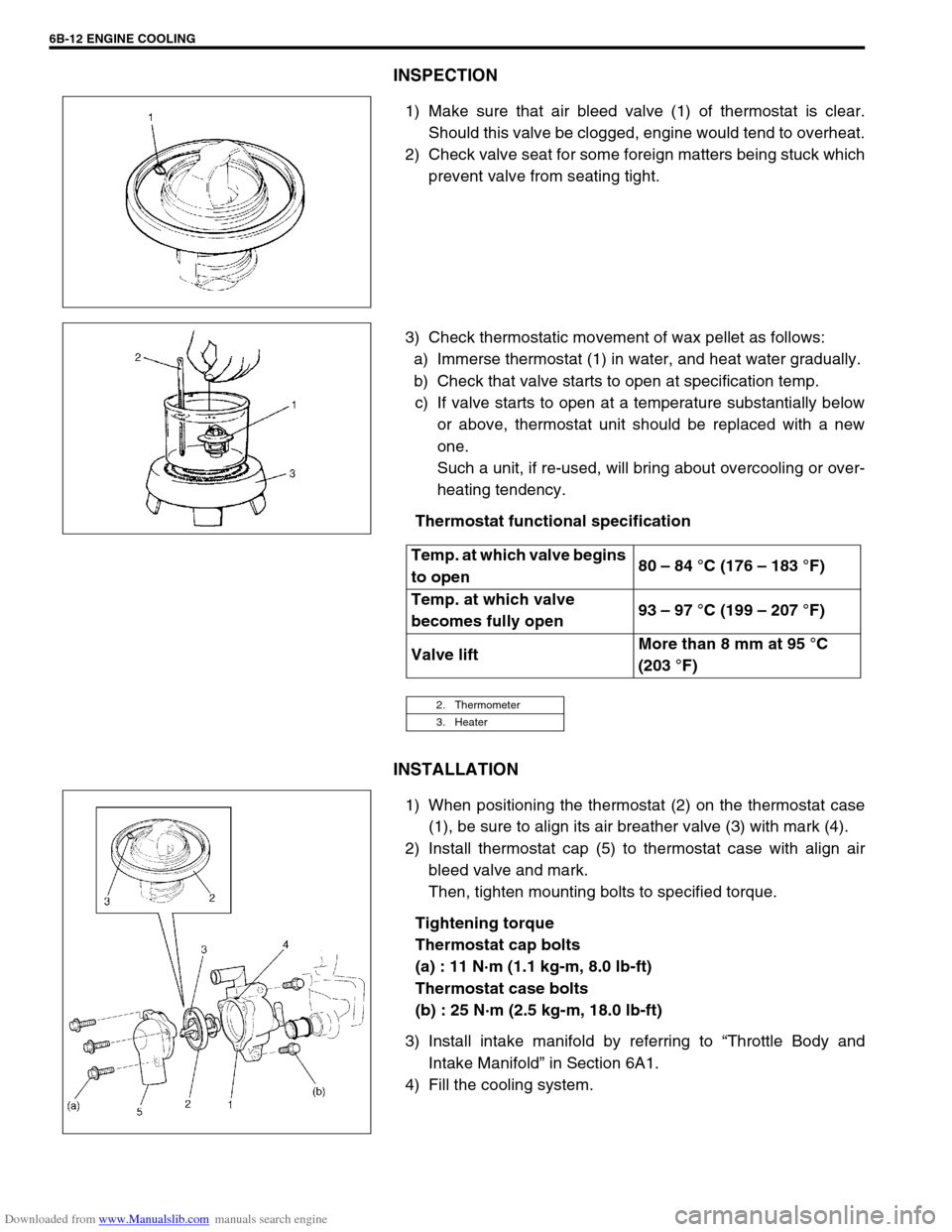
1) Make sure that air bleed valve (1) of thermostat is clear.
Should this valve be clogged, engine would tend to overheat.
2) Check valve seat for some foreign matters being stuck which
prevent valve from seating tight.
3) Check thermostatic movement of wax pellet as follows:
a) Immerse thermostat (1) in water, and heat water gradually.
b) Check that valve starts to open at specification temp.
c) If valve starts to open at a temperature substantially below
or above, thermostat unit should be replaced with a new
one.
Such a unit, if re-used, will bring about overcooling or over-
heating tendency.
Thermostat functional specification
INSTALLATION
1) When positioning the thermostat (2) on the thermostat case
(1), be sure to align its air breather valve (3) with mark (4).
2) Install thermostat cap (5) to thermostat case with align air
bleed valve and mark.
Then, tighten mounting bolts to specified torque.
Tightening torque
Thermostat cap bolts
(a) : 11 N·m (1.1 kg-m, 8.0 lb-ft)
Thermostat case bolts
(b) : 25 N·m (2.5 kg-m, 18.0 lb-ft)
3) Install intake manifold by referring to “Throttle Body and
Intake Manifold” in Section 6A1.
4) Fill the cooling system.
Temp. at which valve begins
to open80 – 84 °C (176 – 183 °F)
Temp. at which valve
becomes fully open93 – 97 °C (199 – 207 °F)
Valve liftMore than 8 mm at 95 °C
(203 °F)
2. Thermometer
3. Heater
Page 599 of 687
Downloaded from www.Manualslib.com manuals search engine 6C-4 ENGINE FUEL
On-Vehicle Service
Before work, refer to “Precaution on Fuel System Service” in Sec-
tion 6.
Fuel Lines
Due to the fact that fuel feed line is under high pressure, use spe-
cial care when servicing it.
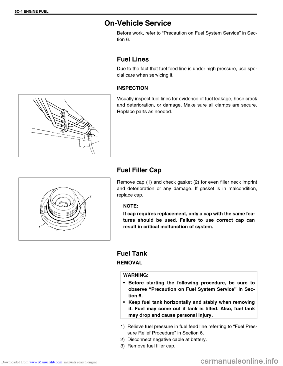
INSPECTION
Visually inspect fuel lines for evidence of fuel leakage, hose crack
and deterioration, or damage. Make sure all clamps are secure.
Replace parts as needed.
Fuel Filler Cap
Remove cap (1) and check gasket (2) for even filler neck imprint
and deterioration or any damage. If gasket is in malcondition,
replace cap.
Fuel Tank
REMOVAL
1) Relieve fuel pressure in fuel feed line referring to “Fuel Pres-
sure Relief Procedure” in Section 6.
2) Disconnect negative cable at battery.
3) Remove fuel filler cap.
NOTE:
If cap requires replacement, only a cap with the same fea-
tures should be used. Failure to use correct cap can
result in critical malfunction of system.
WARNING:
Before starting the following procedure, be sure to
observe “Precaution on Fuel System Service” in Sec-
tion 6.
Keep fuel tank horizontally and stably when removing
it. Fuel may come out if tank is tilted. Also, fuel tank
may drop and cause personal injury.
Page 602 of 687
Downloaded from www.Manualslib.com manuals search engine ENGINE FUEL 6C-7
INSTALLATION
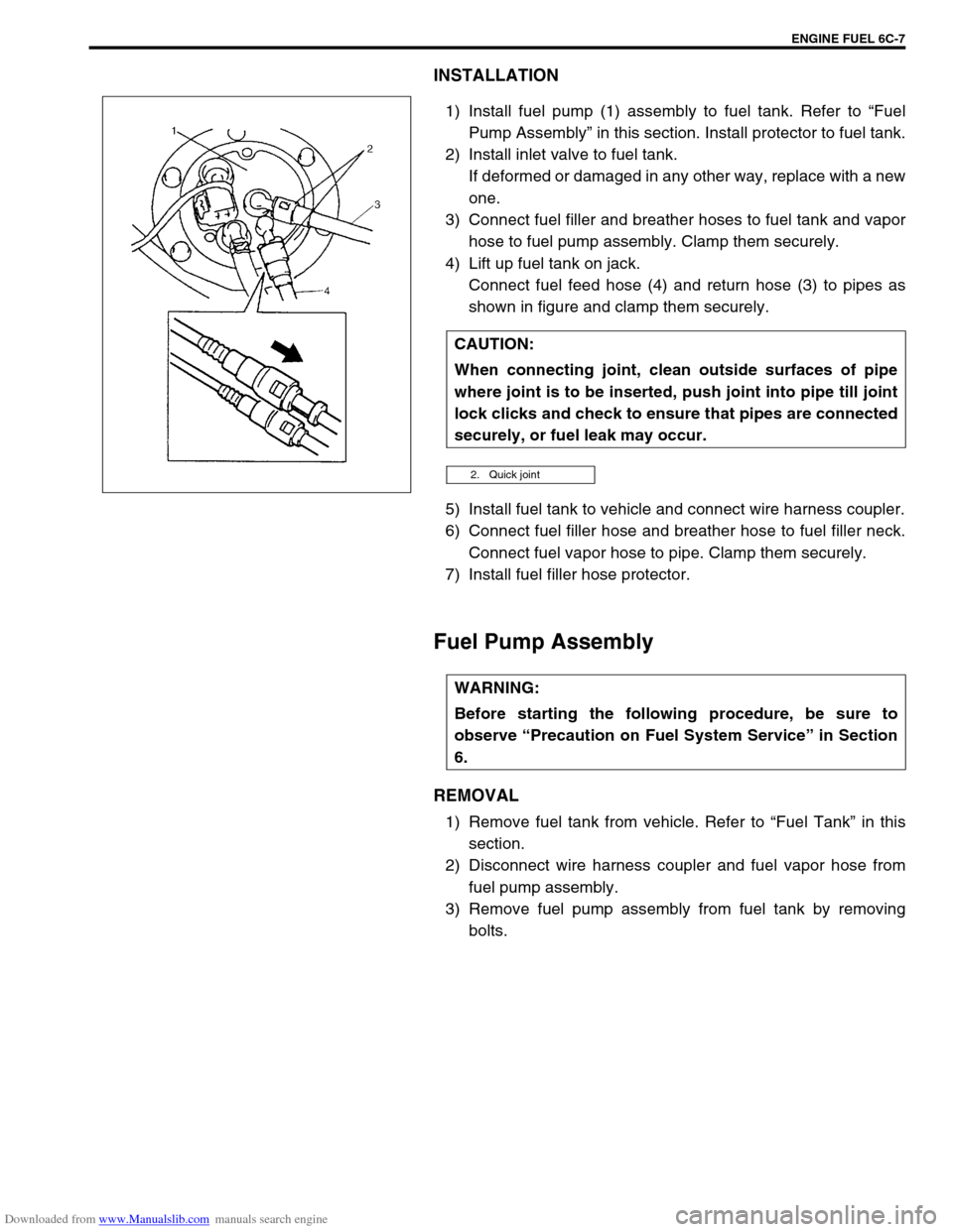
1) Install fuel pump (1) assembly to fuel tank. Refer to “Fuel
Pump Assembly” in this section. Install protector to fuel tank.
2) Install inlet valve to fuel tank.
If deformed or damaged in any other way, replace with a new
one.
3) Connect fuel filler and breather hoses to fuel tank and vapor
hose to fuel pump assembly. Clamp them securely.
4) Lift up fuel tank on jack.
Connect fuel feed hose (4) and return hose (3) to pipes as
shown in figure and clamp them securely.
5) Install fuel tank to vehicle and connect wire harness coupler.
6) Connect fuel filler hose and breather hose to fuel filler neck.
Connect fuel vapor hose to pipe. Clamp them securely.
7) Install fuel filler hose protector.
Fuel Pump Assembly
REMOVAL
1) Remove fuel tank from vehicle. Refer to “Fuel Tank” in this
section.
2) Disconnect wire harness coupler and fuel vapor hose from
fuel pump assembly.
3) Remove fuel pump assembly from fuel tank by removing
bolts. CAUTION:
When connecting joint, clean outside surfaces of pipe
where joint is to be inserted, push joint into pipe till joint
lock clicks and check to ensure that pipes are connected
securely, or fuel leak may occur.
2. Quick joint
WARNING:
Before starting the following procedure, be sure to
observe “Precaution on Fuel System Service” in Section
6.
Page 606 of 687

Downloaded from www.Manualslib.com manuals search engine ENGINE AND EMISSION CONTROL SYSTEM 6E-1
6F1
6F2
6G
7C1
7D
7E
7A
7A1
7B1
7C1
7D
7E
7F
8A
8B
8C
8D
6H
6E
10
10A
10B
SECTION 6E
ENGINE AND EMISSION CONTROL SYSTEM
CONTENTS
General Description ....................................... 6E-3
Air Intake System ......................................... 6E-5
Fuel Delivery System ................................... 6E-6
Fuel pump ................................................ 6E-6
Electronic Control System ............................ 6E-7
Engine & emission control input / output
table.......................................................... 6E-8
On-Vehicle Service....................................... 6E-15
Accelerator cable adjustment ................. 6E-15
Idle speed / idle air control (IAC) duty
inspection ............................................... 6E-15
Idle mixture inspection / adjustment
(vehicle without heated oxygen
sensor) ................................................... 6E-17
Air Intake System ....................................... 6E-18
Throttle body .......................................... 6E-18
Idle air control valve (IAC valve)............. 6E-21
Fuel Delivery System ................................. 6E-22
Fuel pressure inspection ........................ 6E-22
Fuel pump .............................................. 6E-23
Fuel pressure regulator .......................... 6E-24
Fuel injector ............................................ 6E-25
Electronic Control System .......................... 6E-29Engine control module (ECM) ................ 6E-29
Manifold absolute pressure sensor (MAP
sensor) ................................................... 6E-29
Throttle position sensor (TP sensor) ...... 6E-30
Intake air temperature sensor
(IAT sensor) ........................................... 6E-31
Engine coolant temperature sensor
(ECT sensor) .......................................... 6E-32
Heated oxygen sensor
(Sensor-1 and sensor-2) ........................ 6E-33
Camshaft position sensor....................... 6E-34
Crankshaft position sensor..................... 6E-35
Vehicle speed sensor (VSS) .................. 6E-36
Fuel level sensor (GAUGE).................... 6E-36
Knock sensor ......................................... 6E-36
Main relay, fuel pump relay and A/C
condenser fan control relay .................... 6E-36
Fuel cut operation .................................. 6E-37
A/C condenser fan control system ......... 6E-37
A/C condenser fan ................................. 6E-37
Output signals of throttle valve opening
and engine coolant temp.
(Vehicle with A/T only) ........................... 6E-38
Emission Control System ........................... 6E-38 WARNING:
For vehicles equipped with Supplemental Restraint (Air Bag) System:
Service on and around the air bag system components or wiring must be performed only by an
authorized SUZUKI dealer. Refer to “Air Bag System Components and Wiring Location View” under
“General Description” in air bag system section in order to confirm whether you are performing ser-
vice on or near the air bag system components or wiring. Please observe all WARNINGS and “Ser-
vice Precautions” under “On-Vehicle Service” in air bag system section before performing service
on or around the air bag system components or wiring. Failure to follow WARNINGS could result in
unintentional activation of the system or could render the system inoperative. Either of these two
conditions may result in severe injury.
Technical service work must be started at least 90 seconds after the ignition switch is turned to the
“LOCK” position and the negative cable is disconnected from the battery. Otherwise, the system
may be activated by reserve energy in the Sensing and Diagnostic Module (SDM).
NOTE:
Whether following systems (parts) are used in the particular vehicle or not depends on specifications.
Be sure to bear this in mind when performing service work.
EGR valve
Heated oxygen sensor (s) or CO adjusting resistor
Three way catalytic converter (TWC) and warm up three-way catalytic converter (WU-TWC)