Page 60 of 687
Downloaded from www.Manualslib.com manuals search engine HEATER AND VENTILATION 1A-7
Heater Blower Fan Switch
INSPECTION
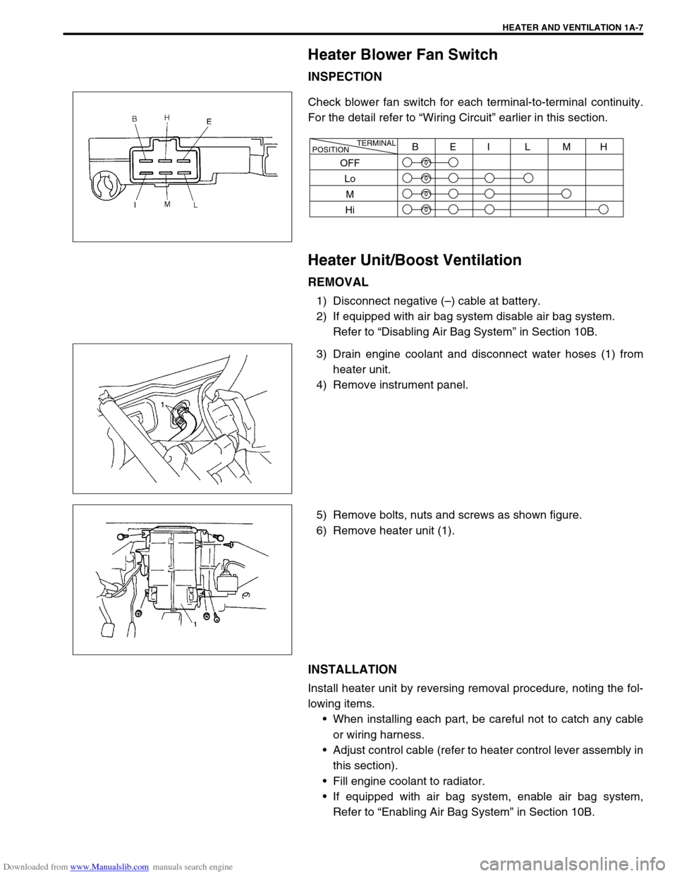
Check blower fan switch for each terminal-to-terminal continuity.
For the detail refer to “Wiring Circuit” earlier in this section.
Heater Unit/Boost Ventilation
REMOVAL
1) Disconnect negative (–) cable at battery.
2) If equipped with air bag system disable air bag system.
Refer to “Disabling Air Bag System” in Section 10B.
3) Drain engine coolant and disconnect water hoses (1) from
heater unit.
4) Remove instrument panel.
5) Remove bolts, nuts and screws as shown figure.
6) Remove heater unit (1).
INSTALLATION
Install heater unit by reversing removal procedure, noting the fol-
lowing items.
When installing each part, be careful not to catch any cable
or wiring harness.
Adjust control cable (refer to heater control lever assembly in
this section).
Fill engine coolant to radiator.
If equipped with air bag system, enable air bag system,
Refer to “Enabling Air Bag System” in Section 10B.
TERMINAL
POSITIONBEI L MH
OFF
Lo
M
Hi
Page 92 of 687
Downloaded from www.Manualslib.com manuals search engine AIR CONDITIONING (OPTIONAL) 1B-31
Condenser Assembly
INSPECTION
Check the following.
Check clog of condenser fins.
If, any clogs are found, condenser fins should be washed
with water, and should be dried with compressed air.
Check condenser fins for leakage and breakage.
If any defects are found, repair or replace condenser.
Check condenser fittings for leakage.
If any defects are found, repair or replace condenser.
REMOVAL
1) Disconnect negative (–) cable at battery.
2) Recover refrigerant from A/C system by referring to “Recov-
ery” in this section.
3) Remove front bumper referring to “Front Bumper” in Section
8.
4) Disconnect A/C condenser cooling fan motor and dual pres-
sure switch connectors.
5) Remove radiator mounting bolts.
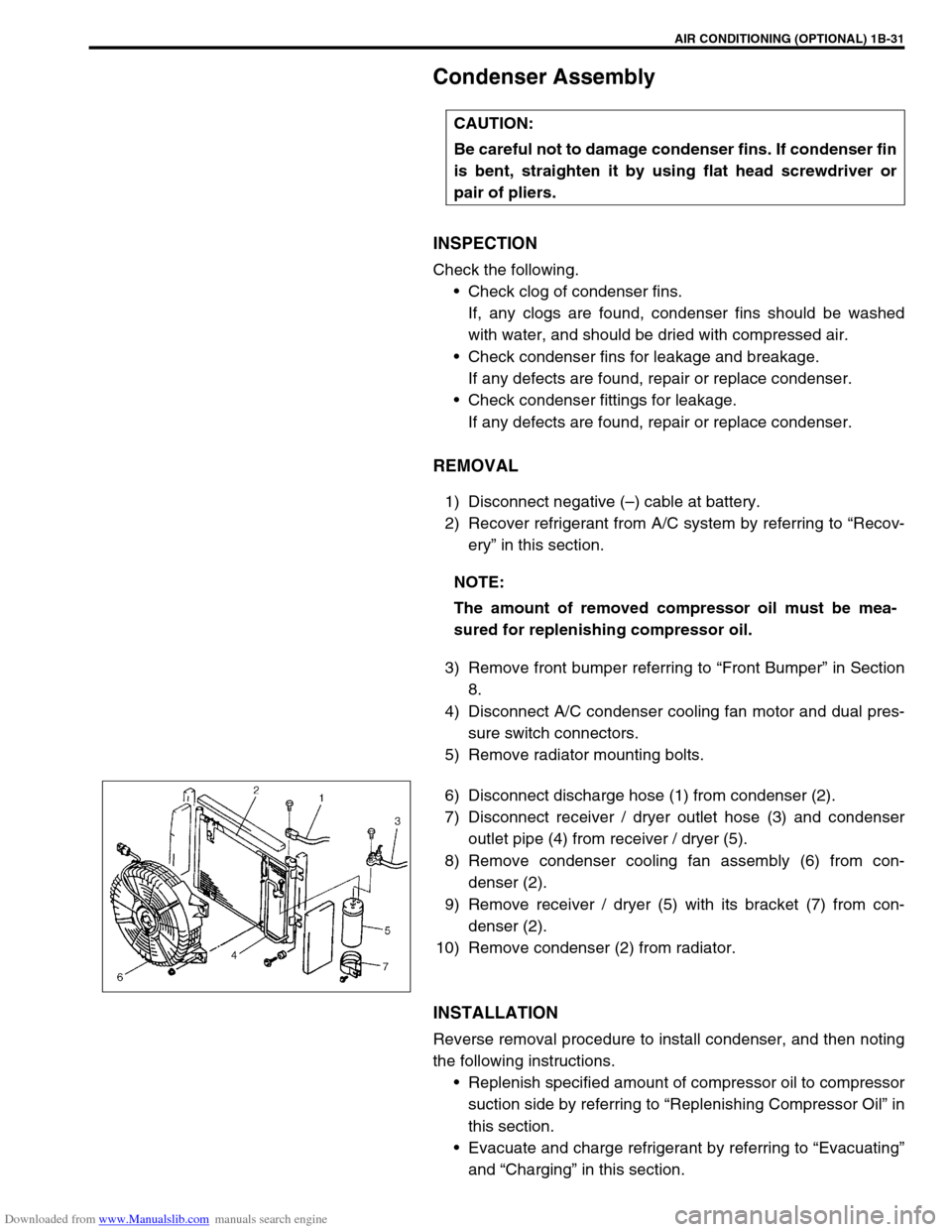
6) Disconnect discharge hose (1) from condenser (2).
7) Disconnect receiver / dryer outlet hose (3) and condenser
outlet pipe (4) from receiver / dryer (5).
8) Remove condenser cooling fan assembly (6) from con-
denser (2).
9) Remove receiver / dryer (5) with its bracket (7) from con-
denser (2).
10) Remove condenser (2) from radiator.
INSTALLATION
Reverse removal procedure to install condenser, and then noting
the following instructions.
Replenish specified amount of compressor oil to compressor
suction side by referring to “Replenishing Compressor Oil” in
this section.
Evacuate and charge refrigerant by referring to “Evacuating”
and “Charging” in this section. CAUTION:
Be careful not to damage condenser fins. If condenser fin
is bent, straighten it by using flat head screwdriver or
pair of pliers.
NOTE:
The amount of removed compressor oil must be mea-
sured for replenishing compressor oil.
Page 94 of 687
Downloaded from www.Manualslib.com manuals search engine AIR CONDITIONING (OPTIONAL) 1B-33
Condenser Cooling Fan Assembly
ASSEMBLY
INSPECTION
1) Check continuity between each two terminals about the con-
denser cooling fan motor (1).
If check results are no continuity, replace condenser cooling
fan motor.
2) Connect battery to condenser cooling fan motor as shown in
figure, then check that the condenser cooling fan motor
operates smoothly.
Reference current of condenser cooling fan motor
approximately 7.5 A at 12 V
REMOVAL
1) Remove front bumper.
2) Disconnect condenser cooling fan motor connector (1).
3) Remove radiator mounting bolts.
4) Remove condenser cooling fan assembly (2) from con-
denser (3).
INSTALLATION
Reverse removal procedure for installation.CAUTION:
Be careful not to damage condenser fins. If condenser fin
is bent, straighten condenser fin by using flat head
screwdriver or pair of pliers.
Page 97 of 687
Downloaded from www.Manualslib.com manuals search engine 1B-36 AIR CONDITIONING (OPTIONAL)
INSTALLATION
Reverse removal procedure to install cooling unit, and then noting
the following instructions.
If A/C evaporator thermistor removed, its should be rein-
stalled in original position.
Install uniformly the packing (1) to installation hole.
Replenish specified amount of compressor oil to compressor
suction side by referring to “Replenishing Compressor Oil” in
this section.
Evacuate and charge refrigerant by referring to “Evacuating”
and “Charging” in this section.
Adjust mode control cable, temperature control cable and
fresh air control cable by referring to “Heater Control Lever
Assembly” in Section 1A.
Enable air bag system referring to “Enable Air Bag System”
in Section 10B. (if equipped)
Fill engine coolant to radiator, referring to “Cooling System
Flush and Refill” in Section 6B.
Page 127 of 687
Downloaded from www.Manualslib.com manuals search engine 3B-6 STEERING GEAR BOX (MANUAL TYPE) AND LINKAGE
On-Vehicle Service
Steering Gear Box
REMOVAL
1) Remove steering lower shaft joint bolt (2).
2) Remove drag rod end nut from pitman arm (1).
3) Disconnect drag rod end (2) from pitman arm (1), using spe-
cial tool.
Special tool
(A) : 09913-65210
4) Remove radiator support member.
5) Remove steering gear box bolts, and remove steering gear
box (1).
6) Remove pitman arm mounting nut (4).
7) Make match marks (3) on pitman arm (1) and sector shaft
(2), for a guide during reinstallation.
8) Remove pitman arm (1) by using puller.
Page 128 of 687
Downloaded from www.Manualslib.com manuals search engine STEERING GEAR BOX (MANUAL TYPE) AND LINKAGE 3B-7
INSTALLATION
Reverse removal procedure to install steering gear box.
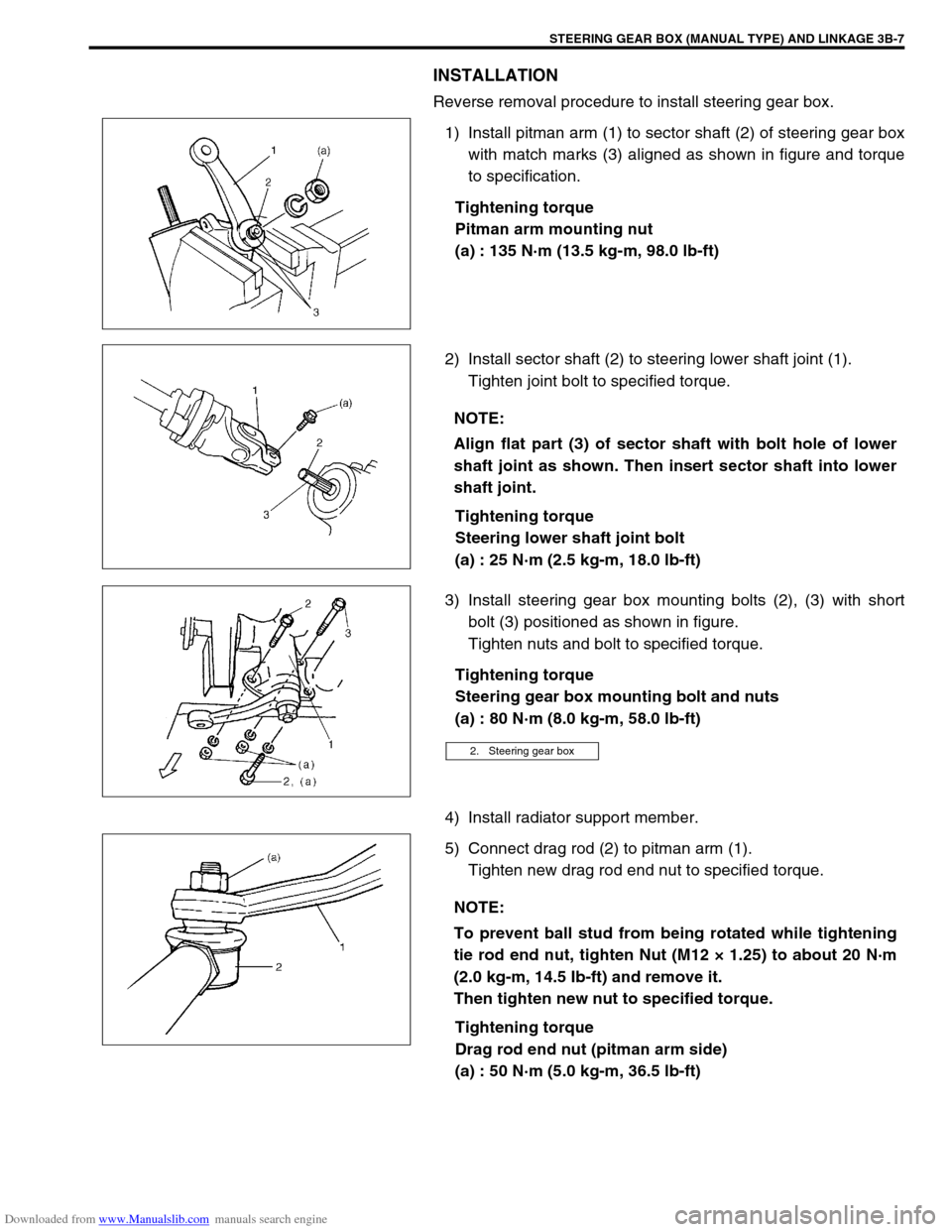
1) Install pitman arm (1) to sector shaft (2) of steering gear box
with match marks (3) aligned as shown in figure and torque
to specification.
Tightening torque
Pitman arm mounting nut
(a) : 135 N·m (13.5 kg-m, 98.0 lb-ft)
2) Install sector shaft (2) to steering lower shaft joint (1).
Tighten joint bolt to specified torque.
Tightening torque
Steering lower shaft joint bolt
(a) : 25 N·m (2.5 kg-m, 18.0 lb-ft)
3) Install steering gear box mounting bolts (2), (3) with short
bolt (3) positioned as shown in figure.
Tighten nuts and bolt to specified torque.
Tightening torque
Steering gear box mounting bolt and nuts
(a) : 80 N·m (8.0 kg-m, 58.0 lb-ft)
4) Install radiator support member.
5) Connect drag rod (2) to pitman arm (1).
Tighten new drag rod end nut to specified torque.
Tightening torque
Drag rod end nut (pitman arm side)
(a) : 50 N·m (5.0 kg-m, 36.5 lb-ft)
NOTE:
Align flat part (3) of sector shaft with bolt hole of lower
shaft joint as shown. Then insert sector shaft into lower
shaft joint.
2. Steering gear box
NOTE:
To prevent ball stud from being rotated while tightening
tie rod end nut, tighten Nut (M12 × 1.25) to about 20 N·m
(2.0 kg-m, 14.5 Ib-ft) and remove it.
Then tighten new nut to specified torque.
Page 149 of 687
Downloaded from www.Manualslib.com manuals search engine 3B1-18 POWER STEERING (P/S) SYSTEM (If equipped)
INSTALLATION
Install components in reverse order of removal procedure noting
the following points.
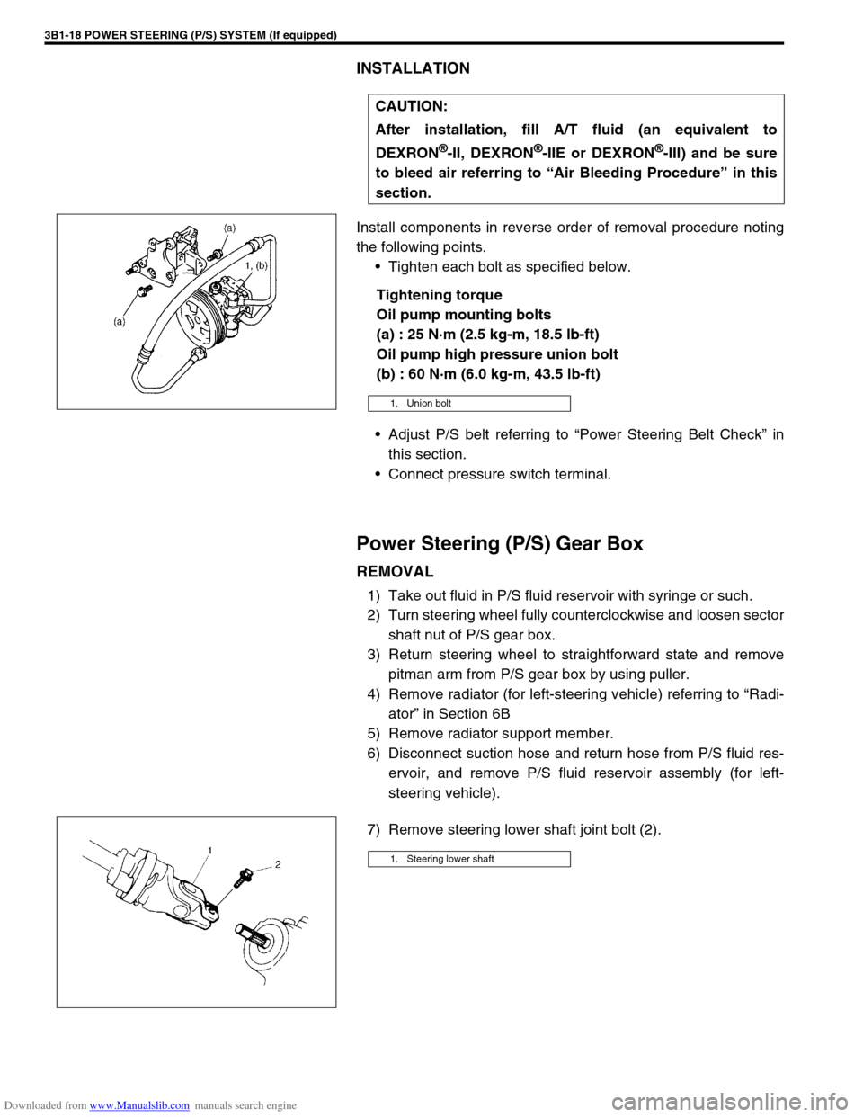
Tighten each bolt as specified below.
Tightening torque
Oil pump mounting bolts
(a) : 25 N·m (2.5 kg-m, 18.5 lb-ft)
Oil pump high pressure union bolt
(b) : 60 N·m (6.0 kg-m, 43.5 lb-ft)
Adjust P/S belt referring to “Power Steering Belt Check” in
this section.
Connect pressure switch terminal.
Power Steering (P/S) Gear Box
REMOVAL
1) Take out fluid in P/S fluid reservoir with syringe or such.
2) Turn steering wheel fully counterclockwise and loosen sector
shaft nut of P/S gear box.
3) Return steering wheel to straightforward state and remove
pitman arm from P/S gear box by using puller.
4) Remove radiator (for left-steering vehicle) referring to “Radi-
ator” in Section 6B
5) Remove radiator support member.
6) Disconnect suction hose and return hose from P/S fluid res-
ervoir, and remove P/S fluid reservoir assembly (for left-
steering vehicle).
7) Remove steering lower shaft joint bolt (2).CAUTION:
After installation, fill A/T fluid (an equivalent to
DEXRON
®-II, DEXRON®-IIE or DEXRON®-III) and be sure
to bleed air referring to “Air Bleeding Procedure” in this
section.
1. Union bolt
1. Steering lower shaft
Page 499 of 687
Downloaded from www.Manualslib.com manuals search engine 6A1-18 ENGINE MECHANICAL (M13 ENGINE)
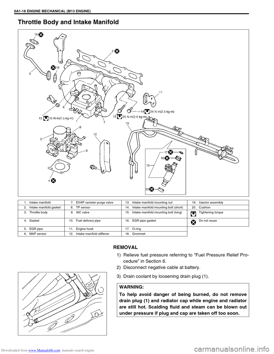
Throttle Body and Intake Manifold
REMOVAL
1) Relieve fuel pressure referring to “Fuel Pressure Relief Pro-
cedure” in Section 6.
2) Disconnect negative cable at battery.
3) Drain coolant by loosening drain plug (1).
1. Intake manifold 7. EVAP canister purge valve 13. Intake manifold mounting nut 19. Injector assembly
2. Intake manifold gasket 8. TP sensor 14. Intake manifold mounting bolt (short) 20. Cushion
3. Throttle body 9. IAC valve 15. Intake manifold mounting bolt (long) Tightening torque
4. Gasket 10. Fuel delivery pipe 16. EGR pipe gasket Do not reuse
5. EGR pipe 11. Engine hook 17. O-ring
6. MAP sensor 12. Intake manifold stiffener 18. Grommet
WARNING:
To help avoid danger of being burned, do not remove
drain plug (1) and radiator cap while engine and radiator
are still hot. Scalding fluid and steam can be blown out
under pressure if plug and cap are taken off too soon.