2005 Seat Ibiza 5D service
[x] Cancel search: servicePage 200 of 252

If and when
198steering wheel on the right the fuses are on the right-hand side of the instru-
ment panel, behind a cover.
The electric windows are protected by circuit breakers. These reset automat-
ically after a few seconds when the overload (caused for example by frozen
windows) has been corrected.
Colour coding of fuses
WARNING
Never “repair” damaged fuses and never replace them with fuses with a
higher rating. Failure to comply could result in fire. This could also cause
damage to other parts of the electrical system.
Note
•
If a newly replaced fuse blows again after a short time, the electrical
system must be checked by a qualified workshop as soon as possible.
•
If you replace a fuse with a stronger fuse, you could cause damage to
another location in the electrical system.
•
Always keep some spare fuses in the vehicle. These are available from
official Service. Colour
Amperes
Beige 5
Brown 7,5
red 10
blue 15
yellow 20
natural (white) 25
green 30
ibiza_ingles Seite 198 Mittwoch, 5. Oktober 2005 5:17 17
Page 206 of 252

If and when
204Some of the electrical items listed in the table are only fitted on certain
models or are optional extras.
Please note that the above list, while corr ect at the time of printing, is subject
to alterations.Lamp changeGeneral notesBefore changing any lamp first turn off the equipment concerned.
Do not touch the lamp glass. Fingerprints vaporise in the heat, causing a
reduction in the lamp life and conden sation on the mirror surface, thus
reducing efficiency.
A lamp should only be placed by one of the same type. The designation is
inscribed on the bulb, either on the glass part or on the base.
It is highly recommended to keep a box of spare lamps in the vehicle. At the
very least, the lamps that most affect road safety should have spares in the
vehicle.
Rear lights on frame
Brake/position 12V/P21/5W
Indicator 12V/P21W Rear lights on tailgate
small position light 12V/W5W
foglight 12V/P21W
reverse light 12V/P21W
Single reflector headlamps
Full / dipped beam 12V 60/55W (H4)
indicator 12V/PY21W
position 12/W5W
Double reflector headlamps
dipped beam 12V/55W (H7)
full lights 12V/55W (H3)
indicator 12V/PY21W
position 12V/W5W
Xenon headlights
7)
Dipped beam 12V/35W (D1S)
8)
full beam 12V/55W (H7)
indicator 12V/PY21W
position lights 12V/W5W
F1
Multi-terminal voltage supply “30”. Internal fuse box 100
G1 Trailer fuse voltage supply in internal fuse box 50
H1 Vacant
Number
Electrical equipment Amperes7)For these type of headlights, the bulbs must be changed by an Authorised Service
Centre, given that complex elements of the vehicle must be removed and that the au-
tomatic control system must be reset.8)Xenon discharge lamps emit 2.5 times as much light flux and have a useful life five
times greater than halogen lamps, this means that, except in case of an abnormal
fault, there is no need to change the bulbs during the vehicle life.
ibiza_ingles Seite 204 Mittwoch, 5. Oktober 2005 5:17 17
Page 207 of 252

If and when205
Safety First
Operating instructions
Tips and Maintenance
Te c h n i c a l D a t a
Fog lights*
Fog light 12V/55W (H3)
Registration plate light
Registration plate light - C5W
Caution
•
The halogen lamps (H3, H7, H4...) are pressurised and might explode on
changing them.
•
Therefore protective gloves and glasses should be worn when changing a
halogen lamp.Note
•
Due to the difficulty in accessing the lamps, these must be changed by an
Authorised Service Centre. However, we shall explain how to change these
lamps, except for the xenon lights*.
Main headlight lamps
Dipped headlights
Main beam headlights
Fig. 140 Main headlight
lampsFig. 141 Main headlight
lamps
AAAB
ibiza_ingles Seite 205 Mittwoch, 5. Oktober 2005 5:17 17
Page 216 of 252
If and when
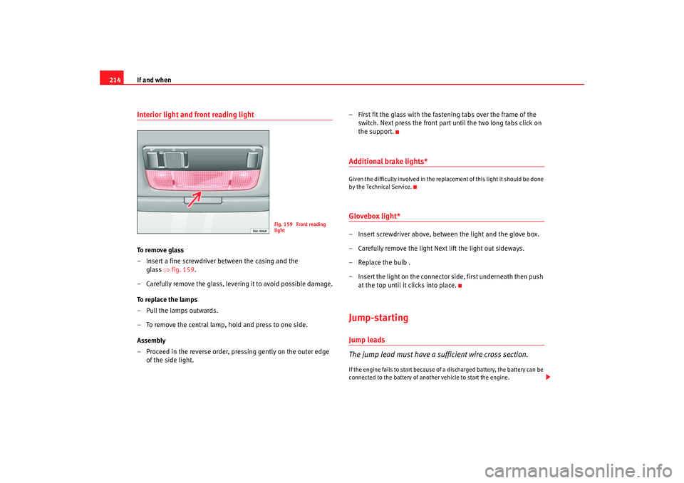
214Interior light and front reading light To r e m o v e g l a s s
– Insert a fine screwdriver between the casing and the
glass ⇒ fig. 159.
– Carefully remove the glass, levering it to avoid possible damage.
To replace the lamps
– Pull the lamps outwards.
– To remove the central lamp, hold and press to one side.
Assembly
– Proceed in the reverse order, pressing gently on the outer edge of the side light. – First fit the glass with the fastening tabs over the frame of the
switch. Next press the front part until the two long tabs click on
the support.
Additional brake lights*Given the difficulty involved in the replacement of this light it should be done
by the Technical Service.Glovebox light*– Insert screwdriver above, between the light and the glove box.
– Carefully remove the light Next lift the light out sideways.
– Replace the bulb .
– Insert the light on the connector side, first underneath then push at the top until it clicks into place.Jump-startingJump leads
The jump lead must have a sufficient wire cross section.If the engine fails to start because of a discharged battery, the battery can be
connected to the battery of anot her vehicle to start the engine.
Fig. 159 Front reading
light
ibiza_ingles Seite 214 Mittwoch, 5. Oktober 2005 5:17 17
Page 223 of 252

General notes on the technical data 221
Safety First
Operating instructions
Tips and Maintenance
Te c h n i c a l D a t a
How are the figures measured?Fuel consumptionFuel consumption and emission values are determined according to Euro-
pean Commission Directive 99/100/EC. They take the actual kerb weight
(weight class) into consideration. To calculate the consumption rate, two measuring cycles are carried out on a rolling road test bed. The test criteria
are as follows:
Note
•
The fuel consumption and emission values quoted in the tables below are
based on an empty basic vehicle without optional extras. The kerb weight of
the vehicle may vary depending on the equipment fitted and thus the weight
category with a relative increase of consumption and emission of CO
2 Your
Authorised Service Centre will be able to inform you of the figures which apply
to your vehicle.
•
Actual consumption may vary from quoted test values, depending on
personal driving style, road and traffic conditions, the weather and the condi-
tion of the vehicle. Urban cycle
The urban cycle starts with an engine cold start. City driving is then simulated.
Extra urban cycle In the extra urban cycle the vehicle undergoes frequent acceleration
and braking in all gears, as in normal everyday driving. The
road speed ranges from 0 to 120 km/h.
Combined The average overall consumption is calculat
ed with a weighting of around 37% for the urban cycle and 63% for the extra urban
cycle.
CO2 emissions The exhaust gases are collected during both driving cycles to calculate carbon dioxide emissions. The gas composition is then
analysed to evaluate the CO
2 content and other emissions.
ibiza_ingles Seite 221 Mittwoch, 5. Oktober 2005 5:17 17
Page 225 of 252

General notes on the technical data 223
Safety First
Operating instructions
Tips and Maintenance
Te c h n i c a l D a t a
Snow chains
Snow chains may be fitted only to the
front wheels. Chains may be used on
the following tyres 155/80 R 13; 165/70 R 14 and 185/80 R 14.
Consult the chapter “wheels” of this manual.
Wheel bolts
After the wheels have been changed, the tightening torque of the wheel bolts
should be checked as soon as possible with a torque wrench ⇒. The tight-
ening torque for steel and alloy wheels is 120 Nm.
WARNING
•
Check the tyre pressure at least once per month. Correct tyre pressure
is very important. If the tyre pressure is too high or too low, there is an
increased danger of accidents, particularly at high speeds.
•
If the torque of the wheel bolts is too low, they could loosen whilst the
vehicle is in motion. Risk of accident! If the tightening torque is too high,
the wheel bolts and threads could be damaged.Note
We recommend that you ask your Authorised Service Centre for information
about appropriate wheel, tyre and snow chain size.
ibiza_ingles Seite 223 Mittwoch, 5. Oktober 2005 5:17 17
Page 226 of 252

Technical Data
224Te c h n i c a l D a t aChecking fluid levelsFrom time to time, the levels of the different fluids in the
vehicle must be checked. Never fi ll with incorrect fluids, to do
so may cause serious damage to the engine.
Radiator expansion tank
Engine oil dipstick.
Engine oil filler cap
Brake fluid reservoir
Battery
Windscreen washer fluid container
The checking and replenishment of the service fluids are carried out on the
components mentioned above. These operations are described in the
⇒ page 169. Overview
Further explanations, instructions and restrictions on the technical data are
contained as
of ⇒ page 219.
Note
The layout of parts may vary according to engine.
Fig. 162 Diagram for the
location of the various
elements
A1A2A3A4A5A6
ibiza_ingles Seite 224 Mittwoch, 5. Oktober 2005 5:17 17
Page 248 of 252

Index
246Rev counter . . . . . . . . . . . . . . . . . . . . . . . . . . . . . 53
Reverse gear
Manual gearbox . . . . . . . . . . . . . . . . . . . . . 129
RME fuel (biodiesel) . . . . . . . . . . . . . . . . . . . . . 168
Roll-back function Sliding/tilting roof . . . . . . . . . . . . . . . . . . . . 87
Windows . . . . . . . . . . . . . . . . . . . . . . . . . . . . 85
Roof aerial* . . . . . . . . . . . . . . . . . . . . . . . . . . . . 163
Roof carrier* . . . . . . . . . . . . . . . . . . . . . . . . . . . . 112
Rubber seals . . . . . . . . . . . . . . . . . . . . . . . . . . . 157
Running in Brake pads . . . . . . . . . . . . . . . . . . . . . . . . . . 143
Engine . . . . . . . . . . . . . . . . . . . . . . . . . . . . . 143
Tyres . . . . . . . . . . . . . . . . . . . . . . . . . . . . . . . 143
Running in tyres . . . . . . . . . . . . . . . . . . . . . . . . 143SSafe driving . . . . . . . . . . . . . . . . . . . . . . . . . . . . . . 7
Safety . . . . . . . . . . . . . . . . . . . . . . . . . . . . . . . . . . . 8
Safety equipment . . . . . . . . . . . . . . . . . . . . . . . . . 7
Safety instructions Coolant temperature . . . . . . . . . . . . . . . . . . . 64
Safety notes Belt tension devices . . . . . . . . . . . . . . . . . . . 26
Curtain airbags . . . . . . . . . . . . . . . . . . . . . . . 39
Disabling front passenger airbag . . . . . . . . 42
Front airbags . . . . . . . . . . . . . . . . . . . . . . . . . 34
Side airbags . . . . . . . . . . . . . . . . . . . . . . . . . 37
Using child seats . . . . . . . . . . . . . . . . . . . . . . 44
Using seat belts . . . . . . . . . . . . . . . . . . . . . . 21 Safety system- safe . . . . . . . . . . . . . . . . . . . . . . . 70
Seals . . . . . . . . . . . . . . . . . . . . . . . . . . . . . . . . . 157
Seat adjustment . . . . . . . . . . . . . . . . . . . . 100, 103
Seat belt position
Pregnant women . . . . . . . . . . . . . . . . . . . . . . 24
Seat belts . . . . . . . . . . . . . . . . . . . . . . . . . . . . 23
Seat belt release . . . . . . . . . . . . . . . . . . . . . . . . . 25
Seat belt warning lamp . . . . . . . . . . . . . . . . . . . . 17
Seat belts . . . . . . . . . . . . . . . . . . . . . . . . . . . . . . . 17 adjustment . . . . . . . . . . . . . . . . . . . . . . . . . . 22
Incorrectly fastened . . . . . . . . . . . . . . . . . . . 26
Not worn . . . . . . . . . . . . . . . . . . . . . . . . . . . . 20
Safety notes . . . . . . . . . . . . . . . . . . . . . . . . . . 21
Warning lamp . . . . . . . . . . . . . . . . . . . . . . . . 17
Seat belts protect . . . . . . . . . . . . . . . . . . . . . . . . 21
Seat heating . . . . . . . . . . . . . . . . . . . . . . . . . . . 104
Seats . . . . . . . . . . . . . . . . . . . . . . . . . . . . . . . . . . 17
Selective opening* . . . . . . . . . . . . . . . . . . . . . . . 71
Semiautomatic air conditioning controls . . . . . . . . . . . . . . . . . . . . . . . . . . . . 116
Service interval display . . . . . . . . . . . . . . . . . . . . 58
Shoes . . . . . . . . . . . . . . . . . . . . . . . . . . . . . . . . . . 14
Side airbags . . . . . . . . . . . . . . . . . . . . . . . . . . . . 34 Description . . . . . . . . . . . . . . . . . . . . . . . . . . 34
Function . . . . . . . . . . . . . . . . . . . . . . . . . . . . . 36
Safety notes . . . . . . . . . . . . . . . . . . . . . . . . . . 37
Side lights . . . . . . . . . . . . . . . . . . . . . . . . . . . . . . 88
Sitting position Driver . . . . . . . . . . . . . . . . . . . . . . . . . . . . . . . . 9
Front passenger . . . . . . . . . . . . . . . . . . . . . . 10 Incorrect sitting position . . . . . . . . . . . . . . . 13
Passengers . . . . . . . . . . . . . . . . . . . . . . . . . . 11
Sitting position, occupants . . . . . . . . . . . . . . . . . 9
Sliding/tilting roof . . . . . . . . . . . . . . . . . . . . . . . 86
Snow chains . . . . . . . . . . . . . . . . . . . . . . . 190, 223
Speedometer . . . . . . . . . . . . . . . . . . . . . . . . . . . . 54
Starting Petrol engines . . . . . . . . . . . . . . . . . . . 127
Starting the engine . . . . . . . . . . . . . . . . . . 126, 127 After the fuel tank has been run dry . . . . . 128
Steam cleaners . . . . . . . . . . . . . . . . . . . . . . . . . 155
Steering . . . . . . . . . . . . . . . . . . . . . . . . . . . . . . . 123 Steering lock . . . . . . . . . . . . . . . . . . . . . . . . 125
Steering wheel controls . . . . . . . . . . . . . . . . . . . 68
Steering wheel height adjustment . . . . . . . . . 123
Stowage frnt right seats . . . . . . . . . . . . . . . . . . . . . . . 107
Stowage compartment Front passenger side . . . . . . . . . . . . . . . . . 106
Sun visors . . . . . . . . . . . . . . . . . . . . . . . . . . . . . . 93
Sunroof . . . . . . . . . . . . . . . . . . . . . . . . . . . . . . . . 86
Sunroof blind Sliding/tilting roof . . . . . . . . . . . . . . . . . . . . 86
Switch Hazard warning lights . . . . . . . . . . . . . . . . . . 90
Rear window heating . . . . . . . . . . . . . . . . . . 89
Switches Electric windows . . . . . . . . . . . . . . . . . . . . . . 83
Electrical exterior mirrors . . . . . . . . . . . . . . . 98
Sliding/tilting roof . . . . . . . . . . . . . . . . . . . . 86
Switching off the engine . . . . . . . . . . . . . . . . . 128
ibiza_ingles Seite 246 Mittwoch, 5. Oktober 2005 5:17 17