Page 1778 of 4555
![NISSAN X-TRAIL 2005 Service Repair Manual EC-1374
[YD (WITHOUT EURO-OBD)]
ON BOARD DIAGNOSTIC (OBD) SYSTEM
HOW TO SWITCH DIAGNOSTIC TEST MODE
NOTE:
�It is better to count the time accurately with a clock.
�It is impossible to switch the dia](/manual-img/5/57403/w960_57403-1777.png "NISSAN X-TRAIL 2005 Service Repair Manual EC-1374
[YD (WITHOUT EURO-OBD)]
ON BOARD DIAGNOSTIC (OBD) SYSTEM
HOW TO SWITCH DIAGNOSTIC TEST MODE
NOTE:
�It is better to count the time accurately with a clock.
�It is impossible to switch the dia")
EC-1374
[YD (WITHOUT EURO-OBD)]
ON BOARD DIAGNOSTIC (OBD) SYSTEM
HOW TO SWITCH DIAGNOSTIC TEST MODE
NOTE:
�It is better to count the time accurately with a clock.
�It is impossible to switch the diagnostic mode when an accelerator pedal position sensor circuit
has a malfunction.
�Always ECM returns to Diagnostic Test Mode I after ignition switch is turned OFF.
How to Set Diagnostic Test Mode II (Self-diagnostic Results)
1. Confirm that accelerator pedal is fully released, turn ignition switch ON and wait 3 seconds.
2. Repeat the following procedure quickly five times within 5 seconds.
a. Fully depress the accelerator pedal.
b. Fully release the accelerator pedal.
3. Wait 7 seconds, fully depress the accelerator pedal and keep it for approx. 10 seconds until the MI starts
blinking.
4. Fully release the accelerator pedal.
ECM has entered to Diagnostic Test Mode II (Self-diagnostic results).
Diagnostic Test
ModeKEY and ENG.
Sta tusFunction Explanation of Function
Mode I Ignition switch in
ON position
Engine stoppedBULB CHECK This function checks the MI bulb for damage (blown, open
circuit, etc.).
If the MI does not come on, check MI circuit. (See EC-
1699, "MI & DATA LINK CONNECTORS" .)
Engine running MALFUNCTION
WARNINGThis is a usual driving condition. When ECM detects a mal-
function, the MI will light up to inform the driver that a mal-
function has been detected.
Mode II Ignition switch in
ON position
Engine stoppedSELF-DIAGNOSTIC
RESULTSThis function allows DTCs to be read.
PBIB0092E
Page 1780 of 4555
EC-1376
[YD (WITHOUT EURO-OBD)]
ON BOARD DIAGNOSTIC (OBD) SYSTEM
Relationship Between MI, DTC, CONSULT-II and Driving PatternsEBS01F89
*1: When a malfunction is detected, MI
will light up.*2: MI will not light up after ignition
switch is turned OFF.*3: When a malfunction is detected for
the first time, the DTC will be stored
in ECM.
*4: Other screens except SELF-DIAG-
NOSTIC RESULTS & DATA MONI-
TOR (AUTO TRIG) cannot display
the malfunction. DATA MONITOR
(AUTO TRIG) can display the mal-
function at the moment it is detected.*5: The DTC will not be displayed any
longer after vehicle is driven 40 times
(Driving pattern A) without the same
malfunction. (The DTC still remain in
ECM.)
MBIB0622E
Page 1792 of 4555
![NISSAN X-TRAIL 2005 Service Repair Manual EC-1388
[YD (WITHOUT EURO-OBD)]
TROUBLE DIAGNOSIS
1 - 5: The numbers refer to the order of inspection.
(continued on next page)
ENGINE CONTROL
Crankshaft position sensor circuit 1 1 1 1 1 1 1 1 1 1E](/manual-img/5/57403/w960_57403-1791.png "NISSAN X-TRAIL 2005 Service Repair Manual EC-1388
[YD (WITHOUT EURO-OBD)]
TROUBLE DIAGNOSIS
1 - 5: The numbers refer to the order of inspection.
(continued on next page)
ENGINE CONTROL
Crankshaft position sensor circuit 1 1 1 1 1 1 1 1 1 1E")
EC-1388
[YD (WITHOUT EURO-OBD)]
TROUBLE DIAGNOSIS
1 - 5: The numbers refer to the order of inspection.
(continued on next page)
ENGINE CONTROL
Crankshaft position sensor circuit 1 1 1 1 1 1 1 1 1 1EC-1512
Camshaft position sensor circuit 3 3EC-1525
Turbocharger boost sensor circuit 1 1 1EC-1659
Turbocharger boost control solenoid
valve circuit111EC-1659
Start signal circuit 1 1 1 1 1 1 1 1 1EC-1696
Ignition switch circuit 1 1 1 1EC-1415
Power supply for ECM circuit 1 1 1 1EC-1415
Cooling fan relay circuitEC-1480
EGR volume control valve circuit 1 1 1EC-1651
Glow relay circuit 1 1 1 1EC-1643
ECM relay (Self-shutoff) circuit 1 1 1 1EC-1584
ECM, connector circuit 2 2 2 2 2 2 2 2 2 2 2 2 2EC-1566,
EC-1641
NATS (Nissan Anti-theft System) 1EC-1373
SYSTEM — Basic engine control systemSYMPTOM
Reference page
HARD/NO START/RESTART (EXCP. HA) ENGINE STALL HESITATION/SURGING/FLAT SPOT KNOCK/DETONATION LACK OF POWER POOR ACCELERATION HI IDLE
LOW IDLE
NO START (with first firing) NO START (without first firing)
HARD TO START WHEN ENGINE IS COLD HARD TO START WHEN ENGINE IS HOT AT I D L E DURING DRIVING WHEN DECELERATING
Warranty symptom code AA AB AC AD AE AF
Page 1794 of 4555
![NISSAN X-TRAIL 2005 Service Repair Manual EC-1390
[YD (WITHOUT EURO-OBD)]
TROUBLE DIAGNOSIS
1 - 5: The numbers refer to the order of inspection.
ENGINE CONTROLCrankshaft position sensor circuit 1 1 1 1EC-1512
Camshaft position sensor circui](/manual-img/5/57403/w960_57403-1793.png "NISSAN X-TRAIL 2005 Service Repair Manual EC-1390
[YD (WITHOUT EURO-OBD)]
TROUBLE DIAGNOSIS
1 - 5: The numbers refer to the order of inspection.
ENGINE CONTROLCrankshaft position sensor circuit 1 1 1 1EC-1512
Camshaft position sensor circui")
EC-1390
[YD (WITHOUT EURO-OBD)]
TROUBLE DIAGNOSIS
1 - 5: The numbers refer to the order of inspection.
ENGINE CONTROLCrankshaft position sensor circuit 1 1 1 1EC-1512
Camshaft position sensor circuit11EC-1525
Turbocharger boost sensor circuit 1 1EC-1506
Turbocharger boost control solenoid valve cir-
cuit11EC-1659
Start signal circuitEC-1696
Ignition switch circuitEC-1415
Power supply for ECM circuit11EC-1415
Cooling fan relay circuit 2EC-1480
EGR volume control valve circuit 1EC-1651
Glow relay circuit1EC-1643
ECM relay (Self-shutoff) circuit1EC-1584
ECM, connector circuit22222222222EC-1566,EC-
1641
NATS (Nissan Anti-theft System)1EC-1373
SYSTEM — Basic engine control systemSYMPTOM
Reference page
ROUGH IDLE/HUNTING IDLING VIBRATION
SLOW/NO RETURN TO IDLE
OVERHEAT/HIGH ENGINE COOLANT TEMPERATURE EXCESSIVE FUEL CONSUMPTION EXCESSIVE OIL CONSUMPTION ABNORMAL SMOKE COLOR
DEAD BATTERY (UNDER CHARGE) Malfunction indicator illuminates.
Can be detected by CONSULT-II?
BLACK SMOKE WHITE SMOKE
Warranty symptom code AG AH AJ AK AL AM AP HA
Page 1803 of 4555
TROUBLE DIAGNOSIS
EC-1399
[YD (WITHOUT EURO-OBD)]
C
D
E
F
G
H
I
J
K
L
MA
EC
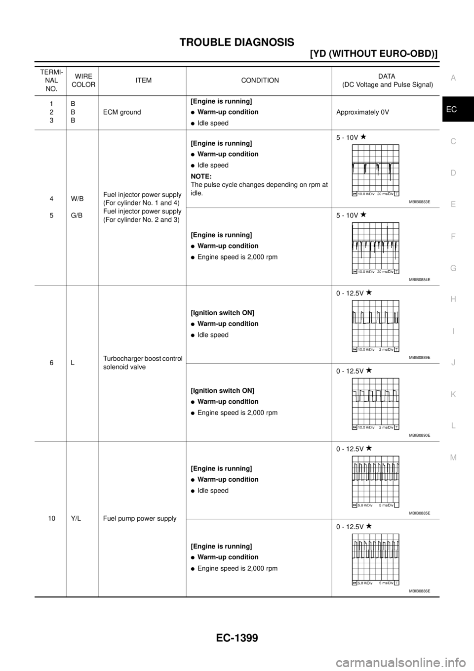
TERMI-
NAL
NO.WIRE
COLORITEM CONDITIONDATA
(DC Voltage and Pulse Signal)
1
2
3B
B
BECM ground[Engine is running]
�Warm-up condition
�Idle speedApproximately 0V
4
5W/B
G/BFuel injector power supply
(For cylinder No. 1 and 4)
Fuel injector power supply
(For cylinder No. 2 and 3)[Engine is running]
�Warm-up condition
�Idle speed
NOTE:
The pulse cycle changes depending on rpm at
idle.5 - 10V
[Engine is running]
�Warm-up condition
�Engine speed is 2,000 rpm5 - 10V
6LTurbocharger boost control
solenoid valve[Ignition switch ON]
�Warm-up condition
�Idle speed0 - 12.5V
[Ignition switch ON]
�Warm-up condition
�Engine speed is 2,000 rpm0 - 12.5V
10 Y/L Fuel pump power supply[Engine is running]
�Warm-up condition
�Idle speed0 - 12.5V
[Engine is running]
�Warm-up condition
�Engine speed is 2,000 rpm0 - 12.5V
MBIB0883E
MBIB0884E
MBIB0889E
MBIB0890E
MBIB0885E
MBIB0886E
Page 1804 of 4555
![NISSAN X-TRAIL 2005 Service Repair Manual EC-1400
[YD (WITHOUT EURO-OBD)]
TROUBLE DIAGNOSIS
14 W/PU Fuel level switch[Ignition switch ON]�Some fuel is in the fuel tankApproximately 0V
[Ignition switch ON]
�No fuel is in the fuel tankBATTERY](/manual-img/5/57403/w960_57403-1803.png "NISSAN X-TRAIL 2005 Service Repair Manual EC-1400
[YD (WITHOUT EURO-OBD)]
TROUBLE DIAGNOSIS
14 W/PU Fuel level switch[Ignition switch ON]�Some fuel is in the fuel tankApproximately 0V
[Ignition switch ON]
�No fuel is in the fuel tankBATTERY")
EC-1400
[YD (WITHOUT EURO-OBD)]
TROUBLE DIAGNOSIS
14 W/PU Fuel level switch[Ignition switch ON]�Some fuel is in the fuel tankApproximately 0V
[Ignition switch ON]
�No fuel is in the fuel tankBATTERY VOLTAGE
(11 - 14V)
19 L Air conditioner relay[Engine is running]
�Air conditioner switch is OFFBATTERY VOLTAGE
(11 - 14V)
[Engine is running]
�Both air conditioner switch and blower fan
switch are ON (Compressor is operating)Approximately 0.1V
21
22
23
24G/R
GY/L
G/R
GY/LFuel injector No. 2
Fuel injector No. 2
Fuel injector No. 3
Fuel injector No. 3[Engine is running]
�Warm-up condition
�Idle speed
NOTE:
The pulse cycle changes depending on rpm at
idle.0 - 9V
[Engine is running]
�Warm-up condition
�Engine speed is 2,000 rpm0 - 9V
25
26
27
28GY
W/L
OR/B
GY/BEGR volume control valve[Engine is running]
�Warm-up condition
�Idle speed0.1 - 14V
(Voltage signals of each ECM ter-
minals differ according to the con-
trol position of EGR volume
control valve.)
29 L Fuel pump[Engine is running]
�Warm-up condition
�Idle speed0.5 - 1.0V
[Engine is running]
�Warm-up condition
�Engine speed is 2,000 rpm0.5 - 1.0V
34 LG/B Cooling fan relay (High)[Engine is running]
�Cooling fan is not operating
�Cooling fan is operating at low speedBATTERY VOLTAGE
(11 - 14V)
[Engine is running]
�Cooling fan is operating at high speedApproximately 0.1V TERMI-
NAL
NO.WIRE
COLORITEM CONDITIONDATA
(DC Voltage and Pulse Signal)
MBIB0881E
MBIB0882E
MBIB0887E
MBIB0888E
Page 1805 of 4555
![NISSAN X-TRAIL 2005 Service Repair Manual TROUBLE DIAGNOSIS
EC-1401
[YD (WITHOUT EURO-OBD)]
C
D
E
F
G
H
I
J
K
L
MA
EC
36 LG Cooling fan relay (Low)[Engine is running]
�Cooling fan is not operating
�Cooling fan is operating at high speedBATT](/manual-img/5/57403/w960_57403-1804.png "NISSAN X-TRAIL 2005 Service Repair Manual TROUBLE DIAGNOSIS
EC-1401
[YD (WITHOUT EURO-OBD)]
C
D
E
F
G
H
I
J
K
L
MA
EC
36 LG Cooling fan relay (Low)[Engine is running]
�Cooling fan is not operating
�Cooling fan is operating at high speedBATT")
TROUBLE DIAGNOSIS
EC-1401
[YD (WITHOUT EURO-OBD)]
C
D
E
F
G
H
I
J
K
L
MA
EC
36 LG Cooling fan relay (Low)[Engine is running]
�Cooling fan is not operating
�Cooling fan is operating at high speedBATTERY VOLTAGE
(11 - 14V)
[Engine is running]
�Cooling fan is operating at low speedApproximately 0.1V
37 W/R Glow relay Refer to EC-1305, "
GLOW CONTROL SYSTEM" .
39 B/OR Fuel transport pump relay[Engine is running]
�Some fuel is in the fuel tankApproximately 0V
[Engine is running]
�No fuel is in the fuel tankBATTERY VOLTAGE
(11 - 14V)
40
41
42
43G/R
GY/L
G/R
GY/LFuel injector No. 4
Fuel injector No. 4
Fuel injector No. 1
Fuel injector No. 1[Engine is running]
�Warm-up condition
�Idle speed
NOTE:
The pulse cycle changes depending on rpm at
idle.0 - 9V
[Engine is running]
�Warm-up condition
�Engine speed is 2,000 rpm0 - 9V
44 L/WCrankshaft position sen-
sor power supply[Ignition switch ON]Approximately 5.3V
45 G/ORCamshaft position sensor
power supply[Ignition switch ON]Approximately 5.3V
46 L Crankshaft position sensor[Engine is running]
�Warm-up condition
�Idle speed
NOTE:
The pulse cycle changes depending on rpm at
idle.0 - 6V
[Engine is running]
�Warm-up condition
�Engine speed is 2,000 rpm0 - 6V TERMI-
NAL
NO.WIRE
COLORITEM CONDITIONDATA
(DC Voltage and Pulse Signal)
MBIB0881E
MBIB0882E
MBIB0879E
MBIB0880E
Page 1806 of 4555
![NISSAN X-TRAIL 2005 Service Repair Manual EC-1402
[YD (WITHOUT EURO-OBD)]
TROUBLE DIAGNOSIS
47 G/R Camshaft position sensor[Engine is running]
�Warm-up condition
�Idle speed
NOTE:
The pulse cycle changes depending on rpm at
idle.0 - 6V
[E](/manual-img/5/57403/w960_57403-1805.png "NISSAN X-TRAIL 2005 Service Repair Manual EC-1402
[YD (WITHOUT EURO-OBD)]
TROUBLE DIAGNOSIS
47 G/R Camshaft position sensor[Engine is running]
�Warm-up condition
�Idle speed
NOTE:
The pulse cycle changes depending on rpm at
idle.0 - 6V
[E")
EC-1402
[YD (WITHOUT EURO-OBD)]
TROUBLE DIAGNOSIS
47 G/R Camshaft position sensor[Engine is running]
�Warm-up condition
�Idle speed
NOTE:
The pulse cycle changes depending on rpm at
idle.0 - 6V
[Engine is running]
�Warm-up condition
�Engine speed is 2,000 rpm0 - 6V
48
49Y/R
RFuel rail pressure sensor[Engine is running]
�Warm-up condition
�Idle speed1.7 - 2.0V
[Engine is running]
�Warm-up condition
�Engine speed is 2,000 rpm2.0 - 2.3V
50 PUFuel pump temperature
sensor[Engine is running]
�Warm-up conditionApproximately 0.3 - 5.3V
Output voltage varies with fuel
pump temperature
51 L/OREngine coolant tempera-
ture sensor[Engine is running]
�Warm-up conditionApproximately 0.3 - 5.3V
Output voltage varies with engine
coolant temperature
52 Y Turbocharger boost sensor[Engine is running]
�Warm-up condition
�Idle speed2.3 - 2.6V
[Engine is running]
�Warm-up condition
�Engine speed is 2,000 rpm2.5 - 2.8V
54 W Mass air flow sensor[Engine is running]
�Warm-up condition
�Idle speed1.8 - 2.3V
[Engine is running]
�Warm-up condition
�Engine speed is 2,000 rpm2.5 - 3.0V
55 GIntake air temperature sen-
sor[Engine is running]
�Warm-up conditionApproximately 0.3 - 5.2V
Output voltage varies with intake
air temperature
59
60
61
62W/B
Y/B
G/B
R/BFuel injector adjustment
resistor No. 1
Fuel injector adjustment
resistor No. 3
Fuel injector adjustment
resistor No. 4
Fuel injector adjustment
resistor No. 2[Ignition switch ON]0.5 - 5.1V
(There are individual differences
between fuel injector adjustment
resistors.) TERMI-
NAL
NO.WIRE
COLORITEM CONDITIONDATA
(DC Voltage and Pulse Signal)
MBIB0877E
MBIB0878E
![NISSAN X-TRAIL 2005 Service Repair Manual EC-1376
[YD (WITHOUT EURO-OBD)]
ON BOARD DIAGNOSTIC (OBD) SYSTEM
Relationship Between MI, DTC, CONSULT-II and Driving PatternsEBS01F89
*1: When a malfunction is detected, MI
will light up.*2: MI wi](/manual-img/5/57403/w960_57403-1779.png "NISSAN X-TRAIL 2005 Service Repair Manual EC-1376
[YD (WITHOUT EURO-OBD)]
ON BOARD DIAGNOSTIC (OBD) SYSTEM
Relationship Between MI, DTC, CONSULT-II and Driving PatternsEBS01F89
*1: When a malfunction is detected, MI
will light up.*2: MI wi")