Page 3101 of 4555
![NISSAN X-TRAIL 2005 Service Repair Manual SYSTEM DESCRIPTION
BRC-53
[ESP/TCS/ABS]
C
D
E
G
H
I
J
K
L
MA
B
BRC
SYSTEM DESCRIPTIONPFP:00000
System DiagramEFS0019X
ESP FunctionEFS0019W
1. The Electronic Stability Program is called the ESP for s](/manual-img/5/57403/w960_57403-3100.png "NISSAN X-TRAIL 2005 Service Repair Manual SYSTEM DESCRIPTION
BRC-53
[ESP/TCS/ABS]
C
D
E
G
H
I
J
K
L
MA
B
BRC
SYSTEM DESCRIPTIONPFP:00000
System DiagramEFS0019X
ESP FunctionEFS0019W
1. The Electronic Stability Program is called the ESP for s")
SYSTEM DESCRIPTION
BRC-53
[ESP/TCS/ABS]
C
D
E
G
H
I
J
K
L
MA
B
BRC
SYSTEM DESCRIPTIONPFP:00000
System DiagramEFS0019X
ESP FunctionEFS0019W
1. The Electronic Stability Program is called the ESP for short. ESP is indicated as ESP on CONSULT-II
screen.
2. In addition to the ABS/TCS function, ESP detects a driver's steering operation amount and brake opera-
tion amount from steering angle sensor and pressure sensor. Using the information from yaw rate/side G
sensor and wheel sensors, ESP judges the driving condition (conditions of understeer and oversteer) to
improve the stability by controlling brake on 4 wheels and engine output.
3. During ESP operation, SLIP indicator lamp flashes to inform the driver of the operation.
CAUTION:
�During ESP operation, body and the brake pedal lightly vibrate and their mechanical noise may be
heard. This is a normal condition.
�If vehicle is rotated on a turn table, or rolled and rocked on a ship, the ABS warning lamp,
ESP OFF indicator lamp, and SLIP indicator lamp may turn on. In this case, start engine on a nor-
mal road again. If the ABS warning lamp, ESP OFF indicator lamp, and SLIP indicator lamp turn
off after the restart, it is normal.
�When driving in a steep slope such as a bank, ABS warning lamp, ESP OFF indicator lamp, and
SLIP indicator lamp may turn on. In this case, start the engine on a normal road again. If ABS
warning lamp, ESP OFF indicator lamp, and SLIP indicator lamp turn off after the restart, it is nor-
mal.
TCS FunctionEFS0019V
1. With the wheel sensor signals from 4 wheels, the ESP/TCS/ABS control unit detects a wheel spin. If a
wheel spins, the control unit controls brake fluid pressure to the spinning wheel, and cuts the fuel to the
engine. It also closes the throttle valve to reduce the engine torque. Furthermore, throttle position is con-
trolled to the appropriate engine torque.
2. If a wheel spins, the TCS system works and function by applying brake fluid pressure to the spinning
wheel.
SFIA2012E
Page 3164 of 4555
![NISSAN X-TRAIL 2005 Service Repair Manual BRC-116
[ESP/TCS/ABS]
WHEEL SENSORS
WHEEL SENSORSPFP:47910
Removal and InstallationEFS001CD
REMOVAL
Pay attention to the following when removing sensor.
CAUTION:
�As much as possible, avoid rotating](/manual-img/5/57403/w960_57403-3163.png "NISSAN X-TRAIL 2005 Service Repair Manual BRC-116
[ESP/TCS/ABS]
WHEEL SENSORS
WHEEL SENSORSPFP:47910
Removal and InstallationEFS001CD
REMOVAL
Pay attention to the following when removing sensor.
CAUTION:
�As much as possible, avoid rotating")
BRC-116
[ESP/TCS/ABS]
WHEEL SENSORS
WHEEL SENSORSPFP:47910
Removal and InstallationEFS001CD
REMOVAL
Pay attention to the following when removing sensor.
CAUTION:
�As much as possible, avoid rotating sensor when removing it. Pull sensors out without pulling on
sensor harness.
�Take care to avoid damaging sensor edges or rotor teeth. Remove wheel sensor first before
removing front or rear wheel hub. This is to avoid damage to sensor wiring and loss of sensor
function.
INSTALLATION
Pay attention to the following when installing sensor. Tighten installation bolts to specified torques.
�When installing, check that there is no foreign material such as iron chips on pick-up and mounting hole of
the sensor. Check that no foreign material has been caught in the sensor rotor. Remove any foreign mate-
rial and clean the mount.
�When installing front sensor, be sure to press rubber grommets in until they lock at the three locations
shown in the figure (2 at strut and 1 at body panel). When installed, harness must not be twisted.
SFIA2203E
Page 3466 of 4555
PS-4
PREPARATION
PREPARATIONPFP:00002
Special Service Tools [SST]EGS0004A
Tool number
Tool nameDescription
ST3127S000
Preload gauge
1. GG9103000
Torque wrench
2. HT62940000
Socket adapter
3. HT62900000
Socket adapterInspecting of steering wheel rotating torque
and rotating torque for ball joint
ST27180001
Steering wheel pullerRemoving steering wheel
KV489Q0020
Teflon ring correcting tool
a: 50 mm (1.97 in) dia.
b: 36 mm (1.42 in) dia.
C: 100 mm (3.94 in)Installing rack Teflon ring
KV48103400
Preload adapterInspecting rotating torque
KV48103500
Oil pressure gauge
KV48102500
Hydraulic pressure gauge adapter
1. KV48102500−01
Eye joint
2. KV48102500−02
Flare joint
3. KV48102500−03
Bolt
4. KV48102500−04
WasherMeasuring oil pump relief pressure
KV48105210
Sprocket holderRemoving power steering oil pump
S-NT541
S-NT544
S-NT550
ZZA0824D
ZZA0839D
ZZA1191D
Page 3467 of 4555
 TROUBLESHOOTING
PS-5
C
D
E
F
H
I
J
K
L
MA
B
PS
NOISE, VIBRATION AND HARSHNESS (NVH) TROUBLESHOOTINGPFP:00003
NVH Trouble shooting ChartEGS000A9
Use chart below t")
NOISE, VIBRATION AND HARSHNESS (NVH) TROUBLESHOOTING
PS-5
C
D
E
F
H
I
J
K
L
MA
B
PS
NOISE, VIBRATION AND HARSHNESS (NVH) TROUBLESHOOTINGPFP:00003
NVH Trouble shooting ChartEGS000A9
Use chart below to help you find the cause of the symptom. If necessary, repair or replace these parts.
×: ApplicableReference page
PS-6PS-6PS-21PS-21PS-21PS-6PS-8PS-8
EM-13
,EM-140PS-8PS-14PS-16PS-13PS-11PS-18
NVH in PR section
NVH in RFD section
NVH in FAX, RAX, FSU, RSU section
NVH in WT section
NVH in WT section
NVH in FAX section
NVH in BR section
Possible cause and SUSPECTED PARTS
Fluid level
Air in hydraulic system
Outer socket ball joint swinging force
Outer socket ball joint rotating torque
Outer socket ball joint end play
Steering fluid leakage
Steering wheel play
Steering gear rack sliding force
Drive belt looseness
Improper steering wheel
Improper installation or looseness or tilt lock lever
Mounting rubber deterioration
Steering column deformation or damage
Improper installation or looseness of steering column
Steering linkage looseness
PROPELLER SHAFT
DIFFERENTIAL
AXLE AND SUSPENSION
TYRES
ROAD WHEEL
DRIVE SHAFT
BRAKES
Symptom STEERINGNoise× × ××××× × × ×××××× ×
Shake××× × ×××× ×
Vibration××××× × ×× ×
Shimmy××× × ××× ×
Judder× × ××× ×
Page 3474 of 4555
, and then remove
lower shaft from vehicle.
5. Lowering vehicle.
6. Loosen clamp, and then remove hole cover seal from hole
cov")
PS-12
STEERING COLUMN
4. Remove fixing bolt of lower shaft (joint part), and then remove
lower shaft from vehicle.
5. Lowering vehicle.
6. Loosen clamp, and then remove hole cover seal from hole
cover.
7. Remove clamp and hole cover from dash panel.
INSTALLATION OF LOWER SHAFT, HOLE COVER, CLAMP AND HOLE COVER SEAL
�Installation in the reverse order of the removal. For tightening torque, refer to PS-11, "COMPONENT" .
�When installing lower shaft to steering gear assembly, follow the procedure listed below.
–Set rack of steering gear in the neutral position.
NOTE:
To get the neutral position of rack, turn gear sub assembly and measure the distance of inner socket, and
then measure the intermediate position of the distance.
–Align rear cover cap projection with the projection of gear sub assembly.
–Install slit part of lower shaft aligning with the projection of rear
cover cap. Make sure that the slit part of lower shaft is aligned
with both the projection of rear cover cap and the marking posi-
tion of gear sub assembly.
REMOVAL OF STEERING COLUMN ASSEMBLY
1. Set vehicle to the straight-ahead position.
2. Remove driver air bag module. Refer to SRS-30, "
DRIVER AIR BAG MODULE" .
3. Remove steering wheel. Refer to PS-10, "
Removal and Installation" .
4. Remove steering column cover (upper and lower), steering lock escutcheon and instrument driver lower
panel. Refer to IP-10, "
INSTRUMENT PANEL ASSEMBLY" .
5. Remove combination switch & spiral cable from steering column assembly. Refer to IP-10, "
INSTRU-
MENT PANEL ASSEMBLY" .
6. Disconnect each switch connectors installed to steering column assembly, and then disconnect harness
from steering column assembly.
7. Remove key interlock cable from steering column assembly. Refer to AT- 4 0 2 , "
KEY INTERLOCK CABLE"
.
8. Remove fixing bolt and nut between column shaft (joint part) and
lower shaft (upper side), and then separate lower shaft from col-
umn shaft (joint part).
SGIA0909E
SGIA0910E
SGIA0908E
Page 3475 of 4555
STEERING COLUMN
PS-13
C
D
E
F
H
I
J
K
L
MA
B
PS
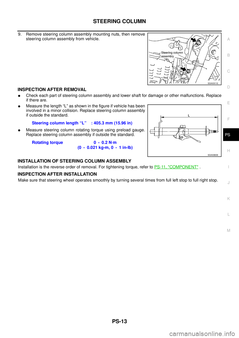
9. Remove steering column assembly mounting nuts, then remove
steering column assembly from vehicle.
INSPECTION AFTER REMOVAL
�Check each part of steering column assembly and lower shaft for damage or other malfunctions. Replace
if there are.
�Measure the length “L” as shown in the figure if vehicle has been
involved in a minor collision. Replace steering column assembly
if outside the standard.
�Measure steering column rotating torque using preload gauge.
Replace steering column assembly if outside the standard.
INSTALLATION OF STEERING COLUMN ASSEMBLY
Installation is the reverse order of removal. For tightening torque, refer to PS-11, "COMPONENT" .
INSPECTION AFTER INSTALLATION
Make sure that steering wheel operates smoothly by turning several times from full left stop to full right stop.
SGIA0911E
Steering column length “L” : 405.3 mm (15.96 in)
Rotating torque 0 - 0.2 N·m
(0 - 0.021 kg-m, 0 - 1 in-lb)
SGIA0883E
Page 3479 of 4555
")
POWER STEERING GEAR AND LINKAGE
PS-17
C
D
E
F
H
I
J
K
L
MA
B
PS
6. Remove steering outer socket from steering knuckle so as not to
damage ball joint boot using the ball joint remover (suitable tool).
CAUTION:
Temporarily tighten the nut to prevent damage to threads
and to prevent the ball joint remover (suitable tool) from
suddenly coming off.
7. Remove high-pressure piping and low-pressure hose of hydrau-
lic piping, and then drain power steering fluid. Refer to PS-37,
"HYDRAULIC LINE" .
8. Remove the power steering tube bracket mounting bolts and
nuts, and then remove power steering tube bracket from steer-
ing gear assembly.
9. Tilt steering gear assembly to prevent any contact with other
parts and then remove it from right side of vehicle.
INSTALLATION
Installation in the reverse order of the removal. For tightening torque, refer to PS-16, "COMPONENT" .
�When installing lower shaft to steering gear, follow the procedure listed below.
–Set rack of steering gear in the neutral position.
NOTE:
To get the neutral position of rack, turn gear sub assembly and measure the distance of inner socket, and
then measure the intermediate position of the distance.
–Align rear cover cap projection with the projection of gear sub assembly.
–Align slit part of lower shaft with the projection of rear cover cap.
And then install it onto rear cover cap of steering gear assembly.
Make sure that the slit part of lower shaft is aligned with both the
projection of rear cover cap and the marking position of gear sub
assembly.
–After installation, bleed air from the steering hydraulic system.
Refer to PS-6, "
Air Bleeding Hydraulic System" .
–Perform final tightening of nuts and bolts on each part under
unladen conditions with tyres on level ground when removing
steering gear assembly. Check wheel alignment. Refer to FSU-
6, "Wheel Alignment" .
–Adjust neutral position of steering angle sensor after checking
wheel alignment. Refer to BRC-52, "
Adjustment of Steering Angle Sensor Neutral Position" .
SGIA1164E
SGIA0912E
SGIA0910E
Page 3506 of 4555

SERVICE DATA AND SPECIFICATIONS (SDS)PFP:00030
Steering WheelEGS0004P
Steering AngleEGS0004Q
Steering ColumnEGS0004R
Steering Outer Socket and Inner Socke")
PS-44
SERVICE DATA AND SPECIFICATIONS (SDS)
SERVICE DATA AND SPECIFICATIONS (SDS)PFP:00030
Steering WheelEGS0004P
Steering AngleEGS0004Q
Steering ColumnEGS0004R
Steering Outer Socket and Inner SocketEGS0004S
Steering wheel axial end play 0 mm (0 in)
Steering wheel play 0 - 35 mm (0 - 1.38 in)
Inner wheel
Degree minute (Decimal degree)Minimum 36° 00′ (36.0°)
Nominal 39° 00′ (39.0°)
Maximum 40° 00′ (40.0°)
Outer wheel
Degree minute (Decimal degree)31° 00′ (31.0°)
Steering column length “L” 405.3 mm (15.96 in)
SGIA0883E
Steering gear type PR24AD
Outer socketSwing torque 0.3 - 2.9 N·m (0.03 - 0.29 kg-m, 3.0 - 25 in-lb)
Measurement on spring balance
Measuring point: cotter pin hole of stud4.84 - 47.4 N (0.49 - 4.84 kg, 1.08 - 10.7 lb)
Rotating torque 0.3 - 2.9 N·m (0.03 - 0.29 kg-m, 3.0 - 25 in-lb)
Axial endplay 0.5 mm (0.02 in) or less
Inner socketSwing torque 1.0 - 7.8 N·m (0.10 - 0.80 kg-m, 9.0 - 69 in-lb)
�Measurement on spring balance
�Measuring point at* mark shown in the figure5.2 - 41 N (0.53 - 4.1 kg, 1.17 - 9.07 lb)
Axial endplay 0.2 mm (0.008 in) or less
Inner socket length “L” 169.67 mm (6.68 in)
SGIA0950E
![NISSAN X-TRAIL 2005 Service Repair Manual PS-4
PREPARATION
PREPARATIONPFP:00002
Special Service Tools [SST]EGS0004A
Tool number
Tool nameDescription
ST3127S000
Preload gauge
1. GG9103000
Torque wrench
2. HT62940000
Socket adapter
3. HT62900](/manual-img/5/57403/w960_57403-3465.png "NISSAN X-TRAIL 2005 Service Repair Manual PS-4
PREPARATION
PREPARATIONPFP:00002
Special Service Tools [SST]EGS0004A
Tool number
Tool nameDescription
ST3127S000
Preload gauge
1. GG9103000
Torque wrench
2. HT62940000
Socket adapter
3. HT62900")