Page 3303 of 4555
BLOWER UNIT
ATC-125
C
D
E
F
G
H
I
K
L
MA
B
AT C
BLOWER UNITPFP:27200
Removal and InstallationEJS000UL
REMOVAL
1. Remove glove box assembly.
2. Remove glove box cover, instrument passenger lower panel and instrument reinforcement. Refer to IP-11,
"Removal and Installation" .
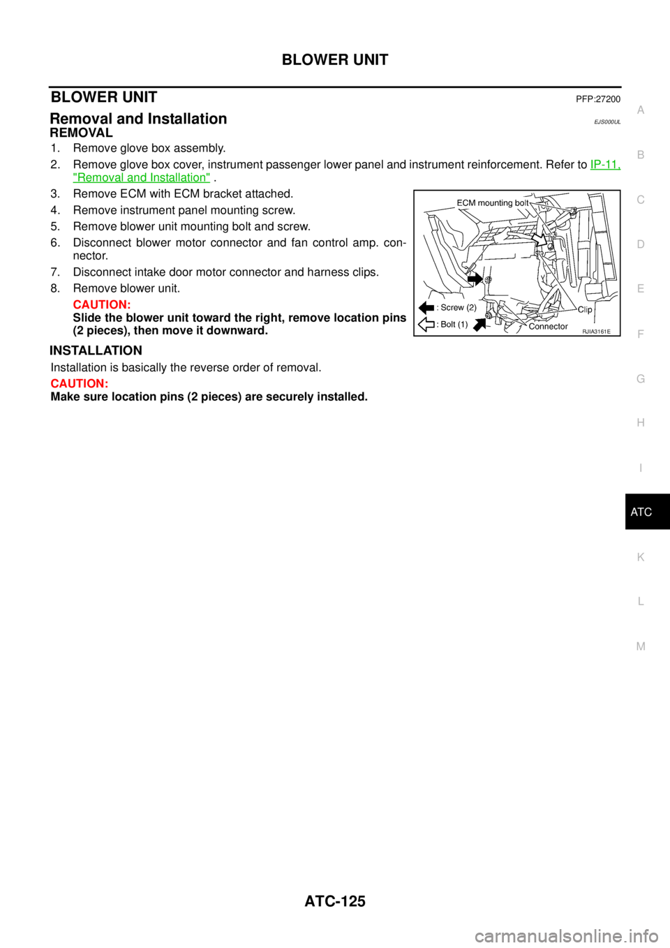
3. Remove ECM with ECM bracket attached.
4. Remove instrument panel mounting screw.
5. Remove blower unit mounting bolt and screw.
6. Disconnect blower motor connector and fan control amp. con-
nector.
7. Disconnect intake door motor connector and harness clips.
8. Remove blower unit.
CAUTION:
Slide the blower unit toward the right, remove location pins
(2 pieces), then move it downward.
INSTALLATION
Installation is basically the reverse order of removal.
CAUTION:
Make sure location pins (2 pieces) are securely installed.
RJIA3161E
Page 3315 of 4555
DUCTS AND GRILLES
ATC-137
C
D
E
F
G
H
I
K
L
MA
B
AT C
DUCTS AND GRILLESPFP:27860
Removal and InstallationEJS004GM
REMOVAL
NOTE:
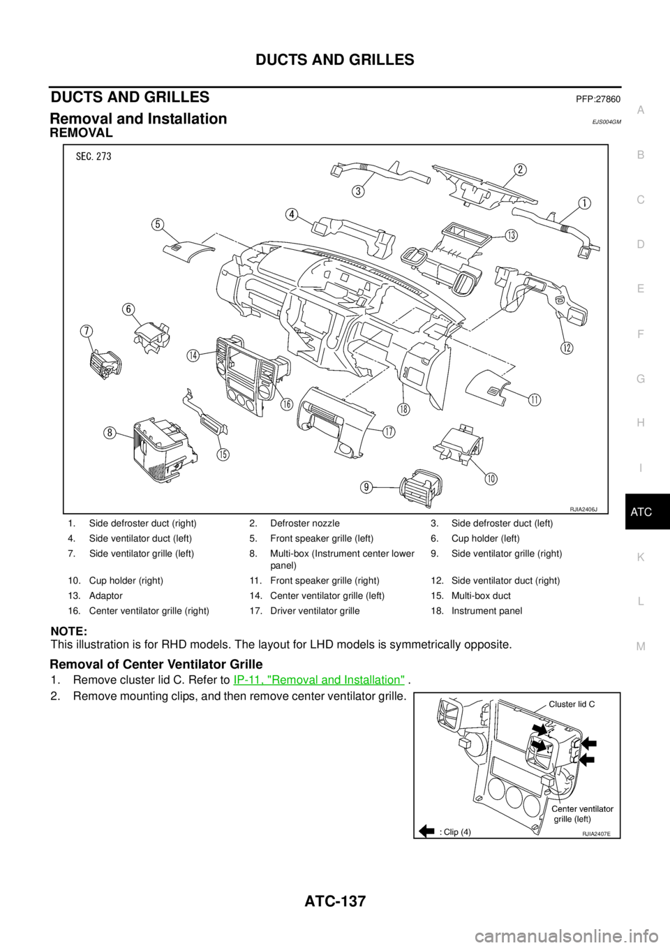
This illustration is for RHD models. The layout for LHD models is symmetrically opposite.
Removal of Center Ventilator Grille
1. Remove cluster lid C. Refer to IP-11, "Removal and Installation" .
2. Remove mounting clips, and then remove center ventilator grille.
1. Side defroster duct (right) 2. Defroster nozzle 3. Side defroster duct (left)
4. Side ventilator duct (left) 5. Front speaker grille (left) 6. Cup holder (left)
7. Side ventilator grille (left) 8. Multi-box (Instrument center lower
panel)9. Side ventilator grille (right)
10. Cup holder (right) 11. Front speaker grille (right) 12. Side ventilator duct (right)
13. Adaptor 14. Center ventilator grille (left) 15. Multi-box duct
16. Center ventilator grille (right) 17. Driver ventilator grille 18. Instrument panel
RJIA2406J
RJIA2407E
Page 3316 of 4555
ATC-138
DUCTS AND GRILLES
Removal of Side Ventilator Grille
1. Remove instrument panel. Refer to IP-11, "Removal and Installation" .
2. Remove side ventilator ducts. Refer to ATC-138, "
Removal of Defroster Nozzle, Duct and Side Ventilator
Duct" .
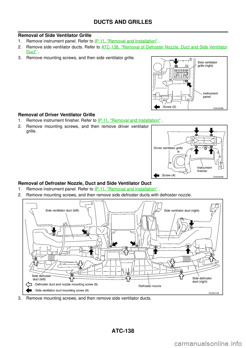
3. Remove mounting screws, and then side ventilator grille.
Removal of Driver Ventilator Grille
1. Remove instrument finisher. Refer to IP-11, "Removal and Installation" .
2. Remove mounting screws, and then remove driver ventilator
grille.
Removal of Defroster Nozzle, Duct and Side Ventilator Duct
1. Remove instrument panel. Refer to IP-11, "Removal and Installation" .
2. Remove mounting screws, and then remove side defroster ducts with defroster nozzle.
3. Remove mounting screws, and then remove side ventilator ducts.
RJIA2408E
RJIA2409E
RJIA2410E
Page 3317 of 4555
DUCTS AND GRILLES
ATC-139
C
D
E
F
G
H
I
K
L
MA
B
AT C
Removal of Adaptor
1. Remove heater & cooling unit. Refer to ATC-131, "HEATER & COOLING UNIT ASSEMBLY" .
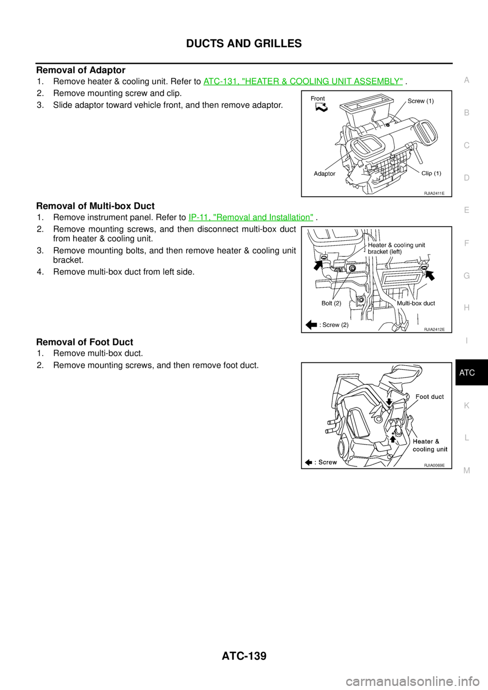
2. Remove mounting screw and clip.
3. Slide adaptor toward vehicle front, and then remove adaptor.
Removal of Multi-box Duct
1. Remove instrument panel. Refer to IP-11, "Removal and Installation" .
2. Remove mounting screws, and then disconnect multi-box duct
from heater & cooling unit.
3. Remove mounting bolts, and then remove heater & cooling unit
bracket.
4. Remove multi-box duct from left side.
Removal of Foot Duct
1. Remove multi-box duct.
2. Remove mounting screws, and then remove foot duct.
RJIA2411E
RJIA2412E
RJIA0069E
Page 3318 of 4555
ATC-140
DUCTS AND GRILLES
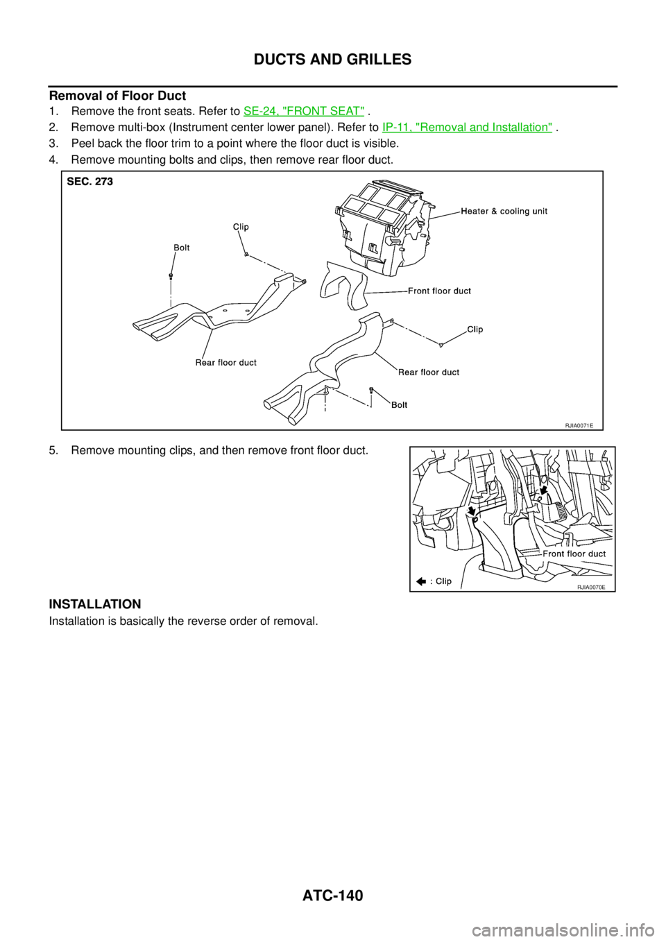
Removal of Floor Duct
1. Remove the front seats. Refer to SE-24, "FRONT SEAT" .
2. Remove multi-box (Instrument center lower panel). Refer to IP-11, "
Removal and Installation" .
3. Peel back the floor trim to a point where the floor duct is visible.
4. Remove mounting bolts and clips, then remove rear floor duct.
5. Remove mounting clips, and then remove front floor duct.
INSTALLATION
Installation is basically the reverse order of removal.
RJIA0071E
RJIA0070E
Page 3331 of 4555
REFRIGERANT LINES
ATC-153
C
D
E
F
G
H
I
K
L
MA
B
AT C
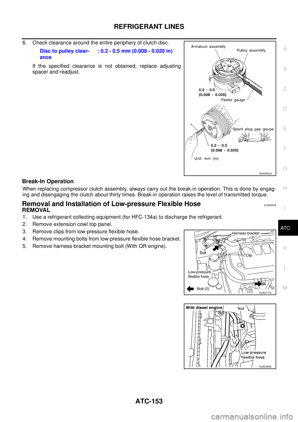
6. Check clearance around the entire periphery of clutch disc.
If the specified clearance is not obtained, replace adjusting
spacer and readjust.
Break-In Operation
When replacing compressor clutch assembly, always carry out the break-in operation. This is done by engag-
ing and disengaging the clutch about thirty times. Break-in operation raises the level of transmitted torque.
Removal and Installation of Low-pressure Flexible HoseEJS000VB
REMOVAL
1. Use a refrigerant collecting equipment (for HFC-134a) to discharge the refrigerant.
2. Remove extension cowl top panel.
3. Remove clips from low-pressure flexible hose.
4. Remove mounting bolts from low-pressure flexible hose bracket.
5. Remove harness bracket mounting bolt (With QR engine).Disc to pulley clear-
ance: 0.2 - 0.5 mm (0.008 - 0.020 in)
RHA080CA
RJIA3177E
RJIA0584E
Page 3336 of 4555
ATC-158
REFRIGERANT LINES
Removal and Installation of Dual-pressure SwitchEJS00289
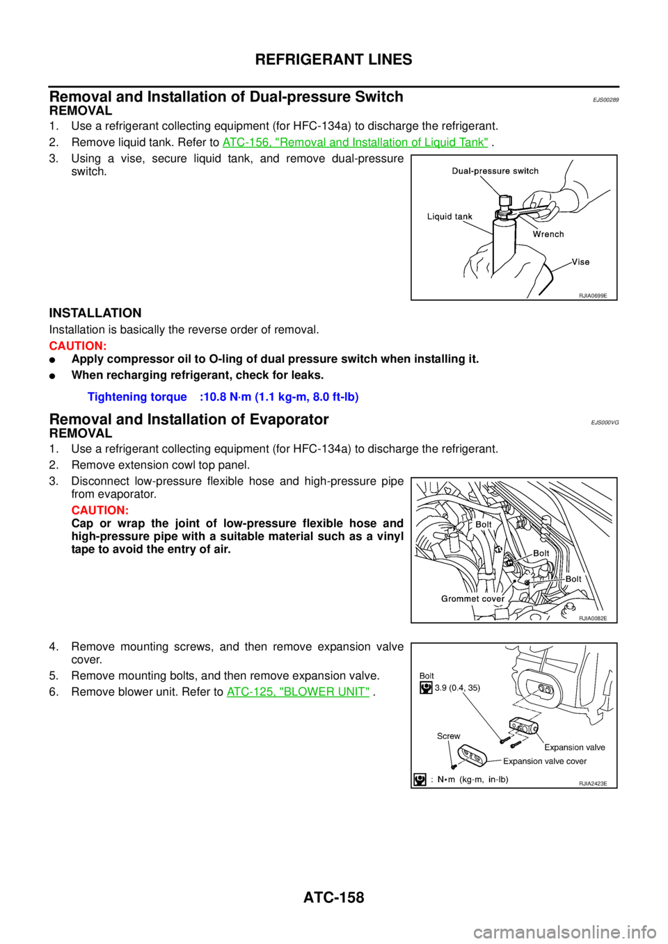
REMOVAL
1. Use a refrigerant collecting equipment (for HFC-134a) to discharge the refrigerant.
2. Remove liquid tank. Refer to ATC-156, "
Removal and Installation of Liquid Tank" .
3. Using a vise, secure liquid tank, and remove dual-pressure
switch.
INSTALLATION
Installation is basically the reverse order of removal.
CAUTION:
�Apply compressor oil to O-ling of dual pressure switch when installing it.
�When recharging refrigerant, check for leaks.
Removal and Installation of EvaporatorEJS000VG
REMOVAL
1. Use a refrigerant collecting equipment (for HFC-134a) to discharge the refrigerant.
2. Remove extension cowl top panel.
3. Disconnect low-pressure flexible hose and high-pressure pipe
from evaporator.
CAUTION:
Cap or wrap the joint of low-pressure flexible hose and
high-pressure pipe with a suitable material such as a vinyl
tape to avoid the entry of air.
4. Remove mounting screws, and then remove expansion valve
cover.
5. Remove mounting bolts, and then remove expansion valve.
6. Remove blower unit. Refer to ATC-125, "
BLOWER UNIT" .
RJIA0699E
Tightening torque :10.8 N·m (1.1 kg-m, 8.0 ft-lb)
RJIA0082E
RJIA2423E
Page 3337 of 4555
REFRIGERANT LINES
ATC-159
C
D
E
F
G
H
I
K
L
MA
B
AT C
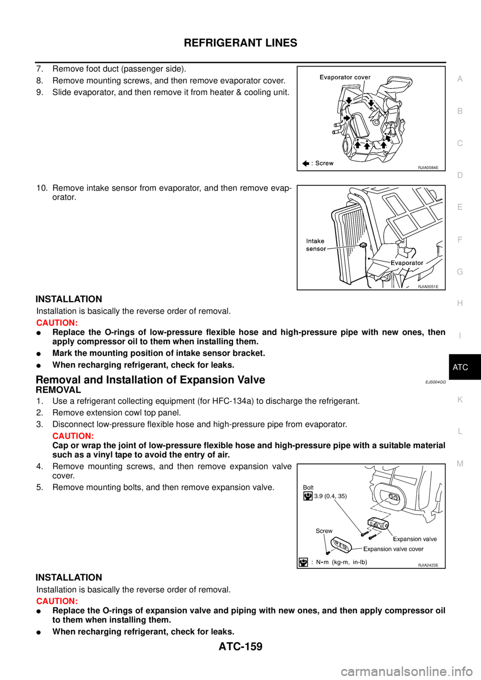
7. Remove foot duct (passenger side).
8. Remove mounting screws, and then remove evaporator cover.
9. Slide evaporator, and then remove it from heater & cooling unit.
10. Remove intake sensor from evaporator, and then remove evap-
orator.
INSTALLATION
Installation is basically the reverse order of removal.
CAUTION:
�Replace the O-rings of low-pressure flexible hose and high-pressure pipe with new ones, then
apply compressor oil to them when installing them.
�Mark the mounting position of intake sensor bracket.
�When recharging refrigerant, check for leaks.
Removal and Installation of Expansion ValveEJS004GG
REMOVAL
1. Use a refrigerant collecting equipment (for HFC-134a) to discharge the refrigerant.
2. Remove extension cowl top panel.
3. Disconnect low-pressure flexible hose and high-pressure pipe from evaporator.
CAUTION:
Cap or wrap the joint of low-pressure flexible hose and high-pressure pipe with a suitable material
such as a vinyl tape to avoid the entry of air.
4. Remove mounting screws, and then remove expansion valve
cover.
5. Remove mounting bolts, and then remove expansion valve.
INSTALLATION
Installation is basically the reverse order of removal.
CAUTION:
�Replace the O-rings of expansion valve and piping with new ones, and then apply compressor oil
to them when installing them.
�When recharging refrigerant, check for leaks.
RJIA0084E
RJIA0051E
RJIA2423E