Page 877 of 4555
FUEL PUMP CIRCUIT
EC-473
[QR (WITH EURO-OBD)]
C
D
E
F
G
H
I
J
K
L
MA
EC
Component InspectionEBS010VL
FUEL PUMP RELAY
Check continuity between terminals 3 and 5 under the following con-
ditions.
FUEL PUMP
1. Disconnect “fuel level sensor unit and fuel pump” harness connector.
2. Check resistance between “fuel level sensor unit and fuel pump”
terminals 3 and 5.
CONDENSER
1. Turn ignition switch OFF.
2. Disconnect condenser harness connector.
3. Check resistance between condenser terminal 1 and 2.
Removal and InstallationEBS010VM
FUEL PUMP
Refer to FL-4, "FUEL LEVEL SENSOR UNIT, FUEL FILTER AND FUEL PUMP ASSEMBLY" .
Conditions Continuity
12V direct current supply between terminals
1 and 2Ye s
No current supply No
PBIB0098E
Resistance: Approximately 0.2 - 5.0Ω [at 25°C
(77°F)]
PBIB0658E
Resistance: Above 1MΩ [at 25°C (77°F)]
MBIB0031E
Page 1317 of 4555
FUEL PUMP CIRCUIT
EC-913
[QR (WITHOUT EURO-OBD)]
C
D
E
F
G
H
I
J
K
L
MA
EC
Component InspectionEBS0114S
FUEL PUMP RELAY
Check continuity between terminals 3 and 5 under the following con-
ditions.
FUEL PUMP
1. Disconnect “fuel level sensor unit and fuel pump” harness connector.
2. Check resistance between “fuel level sensor unit and fuel pump”
terminals 3 and 5.
CONDENSER
1. Turn ignition switch OFF.
2. Disconnect condenser harness connector.
3. Check resistance between condenser terminal 1 and 2.
Removal and InstallationEBS011UV
FUEL PUMP
Refer to FL-4, "FUEL LEVEL SENSOR UNIT, FUEL FILTER AND FUEL PUMP ASSEMBLY" .
Conditions Continuity
12V direct current supply between terminals
1 and 2Ye s
No current supply No
PBIB0098E
Resistance: Approximately 0.2 - 5.0Ω [at 25°C (77°F)]
PBIB0658E
Resistance: Above 1MΩ [at 25°C (77°F)]
MBIB0031E
Page 4153 of 4555

COMBINATION METERS
DI-5
C
D
E
F
G
H
I
J
L
MA
B
DI
TACHOMETER
The tachometer indicates engine speed in revolutions per minute (rpm).
ECM provides an engine speed signal to combination meter for tachometer with CAN communication line.
SPEEDOMETER
ESP/TCS/ABS control unit (with ESP) or ABS actuator and electric unit (without ESP) provides a vehicle
speed signal to the combination meter for the speedometer with CAN communication line.
FUEL GAUGE
The fuel gauge indicates the approximate fuel level in the fuel tank.
The fuel gauge is regulated by a variable ground signal supplied
�from grounds B8 and B18 (LHD models)
�from grounds B107 and B119 (RHD models)
�through terminal 1 and 4 of the fuel level sensor unit
�through terminal 3 and 1 of the sub fuel level sensor unit and
�to combination meter terminal 8 for the fuel gauge.
AMBIENT TEMPERATURE INDICATOR
The ambient temperature is indicated by the signal from ambient sensor.
Combination meter inputs voltage conversed from resistance which ambient sensor detects.
Indication range is between −30 and 55 °C (−22 and 131 °F). When ambient air temperature is less than −30
°C (−22 °F) or more than 55 °C (131 °F), display shows “---°C”. When indicated temperature becomes less
than 3 °C (37 °F), ambient temperature indicator flashes as a sign of warning.
Without Auto A/C
Power is supplied
�through combination meter terminal 27
�to ambient sensor terminal 1.
Ground is supplied
�to combination meter terminal 28
�through ambient sensor terminal 2.
Signal is supplied
�through ambient sensor terminal 1
�to combination meter terminal 27.
With Auto A/C
Power is supplied
�through auto amp terminal 9
�to ambient sensor terminal 1.
Ground is supplied
�to combination meter terminal 28 and auto amp terminal 24
�through ambient sensor terminal 2.
And combination meter receives ambient sensor signal from ambient sensor
�through ambient sensor terminal 1
�to combination meter terminal 27.
NOTE:
Combination meter distinguishes whether or not the combination meter terminal 29 receives voltage (auto A/C
recognition signal) from auto amp terminal 28. If the terminal receives, combination meter discerns as auto A/
C.
Indication When Turning Ignition Switch OFF
�In a case that temperature detected by ambient sensor is higher than indicated temperature before turn-
ing ignition switch OFF.
–In a case of more than 3.5 hours after turning ignition switch OFF, temperature detected by ambient sen-
sor is indicated when turning ignition switch ON.
Page 4180 of 4555
DI-32
COMBINATION METERS
Electrical Components InspectionEKS00INH
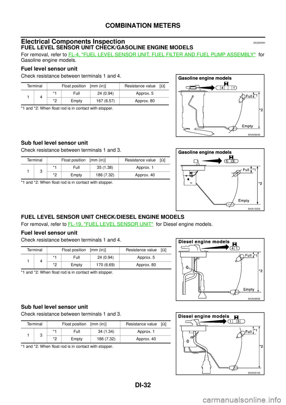
FUEL LEVEL SENSOR UNIT CHECK/GASOLINE ENGINE MODELS
For removal, refer to FL-4, "FUEL LEVEL SENSOR UNIT, FUEL FILTER AND FUEL PUMP ASSEMBLY" for
Gasoline engine models.
Fuel level sensor unit
Check resistance between terminals 1 and 4.
*1 and *2: When float rod is in contact with stopper.
Sub fuel level sensor unit
Check resistance between terminals 1 and 3.
*1 and *2: When float rod is in contact with stopper.
FUEL LEVEL SENSOR UNIT CHECK/DIESEL ENGINE MODELS
For removal, refer to FL-19, "FUEL LEVEL SENSOR UNIT" for Diesel engine models.
Fuel level sensor unit
Check resistance between terminals 1 and 4.
*1 and *2: When float rod is in contact with stopper.
Sub fuel level sensor unit
Check resistance between terminals 1 and 3.
*1 and *2: When float rod is in contact with stopper.Terminal Float position [mm (in)] Resistance value [Ω]
14*1 Full 24 (0.94) Approx. 5
*2 Empty 167 (6.57) Approx. 80
SKIA0904E
Terminal Float position [mm (in)] Resistance value [Ω]
13*1 Full 35 (1.38) Approx. 1
*2 Empty 186 (7.32) Approx. 40
SKIA1032E
Terminal Float position [mm (in)] Resistance value [Ω]
14*1 Full 24 (0.94) Approx. 5
*2 Empty 170 (6.69) Approx. 80
SKIA0909E
Terminal Float position [mm (in)] Resistance value [Ω]
13*1 Full 34 (1.34) Approx. 1
*2 Empty 186 (7.32) Approx. 40
SKIA0910E
![NISSAN X-TRAIL 2005 Service Repair Manual FUEL PUMP CIRCUIT
EC-473
[QR (WITH EURO-OBD)]
C
D
E
F
G
H
I
J
K
L
MA
EC
Component InspectionEBS010VL
FUEL PUMP RELAY
Check continuity between terminals 3 and 5 under the following con-
ditions.
FUEL](/manual-img/5/57403/w960_57403-876.png "NISSAN X-TRAIL 2005 Service Repair Manual FUEL PUMP CIRCUIT
EC-473
[QR (WITH EURO-OBD)]
C
D
E
F
G
H
I
J
K
L
MA
EC
Component InspectionEBS010VL
FUEL PUMP RELAY
Check continuity between terminals 3 and 5 under the following con-
ditions.
FUEL")
![NISSAN X-TRAIL 2005 Service Repair Manual FUEL PUMP CIRCUIT
EC-913
[QR (WITHOUT EURO-OBD)]
C
D
E
F
G
H
I
J
K
L
MA
EC
Component InspectionEBS0114S
FUEL PUMP RELAY
Check continuity between terminals 3 and 5 under the following con-
ditions.
F](/manual-img/5/57403/w960_57403-1316.png "NISSAN X-TRAIL 2005 Service Repair Manual FUEL PUMP CIRCUIT
EC-913
[QR (WITHOUT EURO-OBD)]
C
D
E
F
G
H
I
J
K
L
MA
EC
Component InspectionEBS0114S
FUEL PUMP RELAY
Check continuity between terminals 3 and 5 under the following con-
ditions.
F")