COMBINATION METERS
DI-25
C
D
E
F
G
H
I
J
L
MA
B
DI
Fuel Level Sensor Signal Inspection [Gasoline Engine Models]EKS00EHC
The following symptoms are not malfunction.
FUEL GAUGE
�Depending on vehicle posture or driving circumstance, the fuel level changes and the pointer may fluctu-
ate.
�If the vehicle is fueled with the ignition switch ON, the pointer will move slowly.
LOW-FUEL WARNING LAMP
Depending on vehicle posture or driving circumstance, the fuel level changes and the warning lamp ON timing
may change.
1. CHECK HARNESS CONNECTOR
Check combination meter and fuel level sensor unit terminals (meter side, unit side, harness side) for loose-
ness or bent terminals.
OK or NG
OK >> GO TO 2.
NG >> Repair terminal or connector.
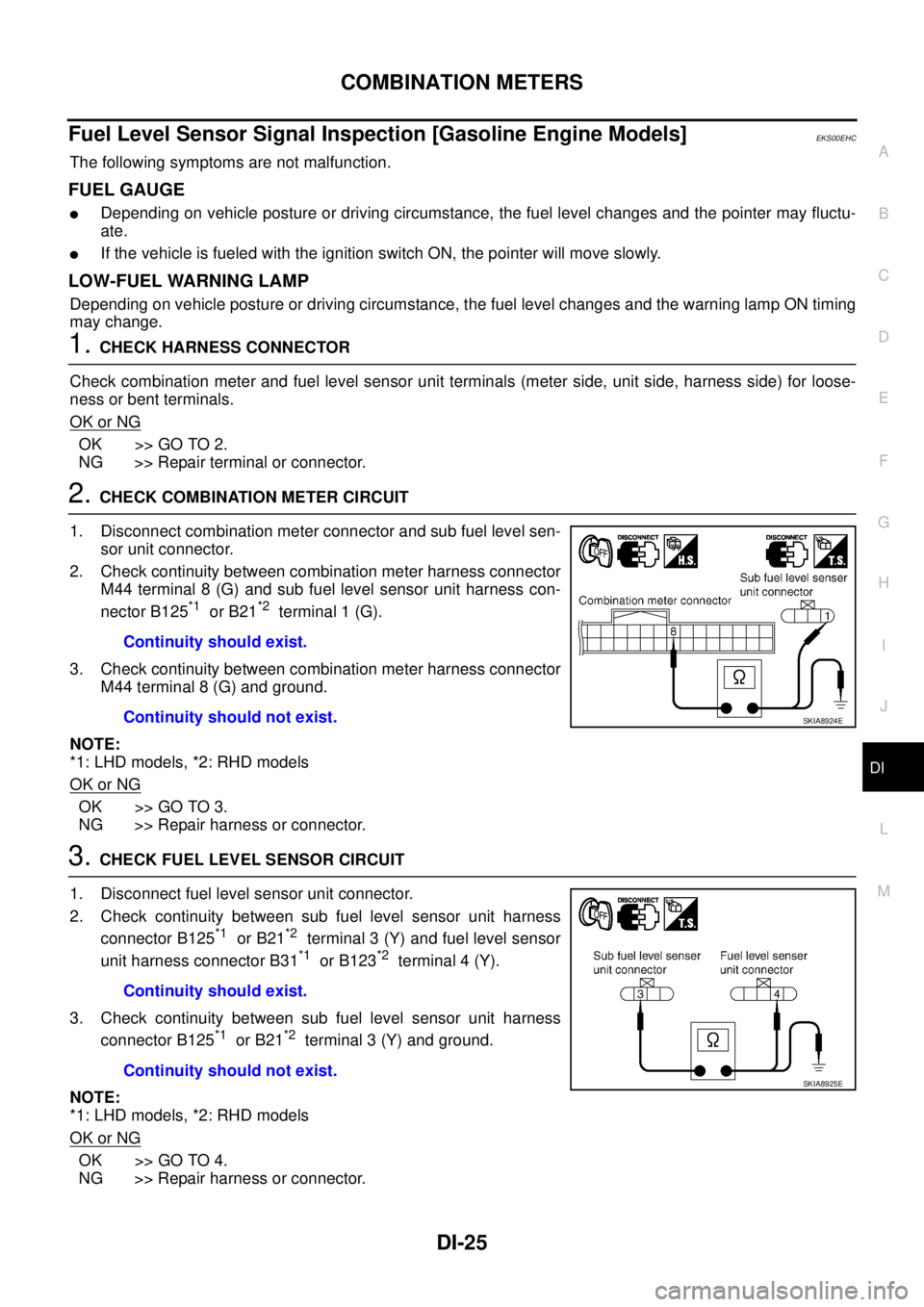
2. CHECK COMBINATION METER CIRCUIT
1. Disconnect combination meter connector and sub fuel level sen-
sor unit connector.
2. Check continuity between combination meter harness connector
M44 terminal 8 (G) and sub fuel level sensor unit harness con-
nector B125
*1 or B21*2 terminal 1 (G).
3. Check continuity between combination meter harness connector
M44 terminal 8 (G) and ground.
NOTE:
*1: LHD models, *2: RHD models
OK or NG
OK >> GO TO 3.
NG >> Repair harness or connector.
3. CHECK FUEL LEVEL SENSOR CIRCUIT
1. Disconnect fuel level sensor unit connector.
2. Check continuity between sub fuel level sensor unit harness
connector B125
*1 or B21*2 terminal 3 (Y) and fuel level sensor
unit harness connector B31
*1 or B123*2 terminal 4 (Y).
3. Check continuity between sub fuel level sensor unit harness
connector B125
*1 or B21*2 terminal 3 (Y) and ground.
NOTE:
*1: LHD models, *2: RHD models
OK or NG
OK >> GO TO 4.
NG >> Repair harness or connector.Continuity should exist.
Continuity should not exist.
SKIA8924E
Continuity should exist.
Continuity should not exist.
SKIA8925E
COMBINATION METERS
DI-27
C
D
E
F
G
H
I
J
L
MA
B
DI
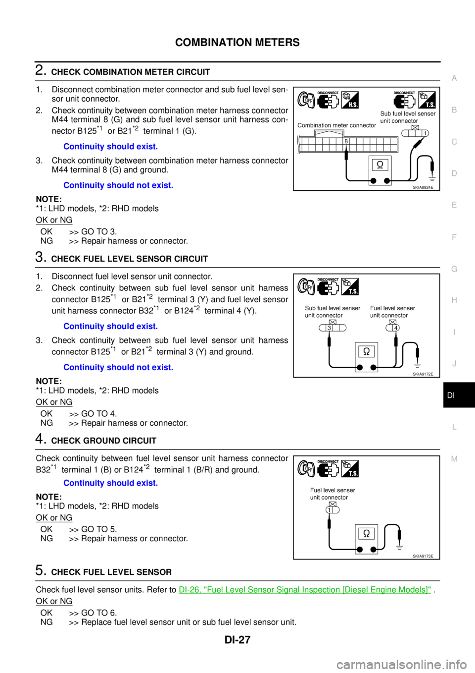
2. CHECK COMBINATION METER CIRCUIT
1. Disconnect combination meter connector and sub fuel level sen-
sor unit connector.
2. Check continuity between combination meter harness connector
M44 terminal 8 (G) and sub fuel level sensor unit harness con-
nector B125
*1 or B21*2 terminal 1 (G).
3. Check continuity between combination meter harness connector
M44 terminal 8 (G) and ground.
NOTE:
*1: LHD models, *2: RHD models
OK or NG
OK >> GO TO 3.
NG >> Repair harness or connector.
3. CHECK FUEL LEVEL SENSOR CIRCUIT
1. Disconnect fuel level sensor unit connector.
2. Check continuity between sub fuel level sensor unit harness
connector B125
*1 or B21*2 terminal 3 (Y) and fuel level sensor
unit harness connector B32
*1 or B124*2 terminal 4 (Y).
3. Check continuity between sub fuel level sensor unit harness
connector B125
*1 or B21*2 terminal 3 (Y) and ground.
NOTE:
*1: LHD models, *2: RHD models
OK or NG
OK >> GO TO 4.
NG >> Repair harness or connector.
4. CHECK GROUND CIRCUIT
Check continuity between fuel level sensor unit harness connector
B32
*1 terminal 1 (B) or B124*2 terminal 1 (B/R) and ground.
NOTE:
*1: LHD models, *2: RHD models
OK or NG
OK >> GO TO 5.
NG >> Repair harness or connector.
5. CHECK FUEL LEVEL SENSOR
Check fuel level sensor units. Refer to DI-26, "
Fuel Level Sensor Signal Inspection [Diesel Engine Models]" .
OK or NG
OK >> GO TO 6.
NG >> Replace fuel level sensor unit or sub fuel level sensor unit.Continuity should exist.
Continuity should not exist.
SKIA8924E
Continuity should exist.
Continuity should not exist.
SKIA9172E
Continuity should exist.
SKIA9173E