Page 3094 of 4555
![NISSAN X-TRAIL 2005 Service Repair Manual BRC-46
[ABS]
WHEEL SENSORS
WHEEL SENSORSPFP:47910
Removal and InstallationEFS004GR
REMOVAL
Pay attention to the following when removing sensor.
CAUTION:
�As much as possible, avoid rotating sensor w](/manual-img/5/57403/w960_57403-3093.png "NISSAN X-TRAIL 2005 Service Repair Manual BRC-46
[ABS]
WHEEL SENSORS
WHEEL SENSORSPFP:47910
Removal and InstallationEFS004GR
REMOVAL
Pay attention to the following when removing sensor.
CAUTION:
�As much as possible, avoid rotating sensor w")
BRC-46
[ABS]
WHEEL SENSORS
WHEEL SENSORSPFP:47910
Removal and InstallationEFS004GR
REMOVAL
Pay attention to the following when removing sensor.
CAUTION:
�As much as possible, avoid rotating sensor when removing it. Pull sensors out without pulling on
sensor harness.
�Take care to avoid damaging sensor edges or rotor teeth. Remove wheel sensor first before
removing front or rear wheel hub. This is to avoid damage to sensor wiring and loss of sensor
function.
INSTALLATION
Pay attention to the following when installing sensor. Tighten installation bolts to specified torques.
�When installing, check that there is no foreign material such as iron chips on pick-up and mounting hole of
the sensor. Check that no foreign material has been caught in the sensor rotor. Remove any foreign mate-
rial and clean the mount.
�When installing front sensor, be sure to press rubber grommets in until they lock at the three locations
shown in the figure (2 at strut and 1 at body panel). When installed, harness must not be twisted.
SFIA1100E
Page 3095 of 4555
G SENSOR
BRC-47
[ABS]
C
D
E
G
H
I
J
K
L
MA
B
BRC
G SENSORPFP:47930
Removal and InstallationEFS004GY
CAUTION:
�Do not drop or strike the G sensor, because it is sensitive to impact.
�Do not use power tool, etc. Because G sensor is weak for the impact.
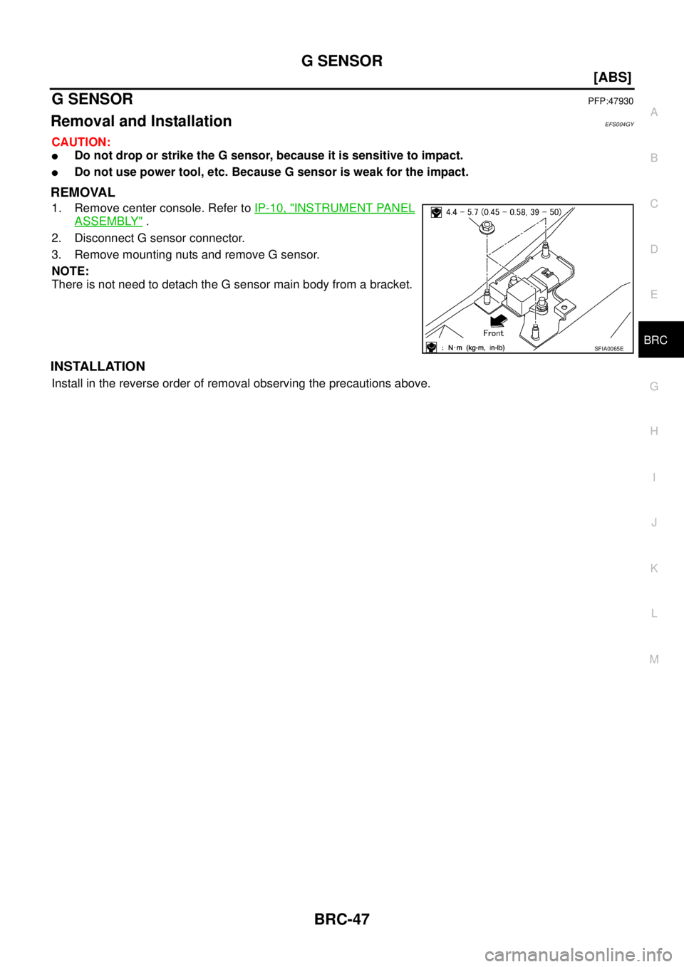
REMOVAL
1. Remove center console. Refer to IP-10, "INSTRUMENT PANEL
ASSEMBLY" .
2. Disconnect G sensor connector.
3. Remove mounting nuts and remove G sensor.
NOTE:
There is not need to detach the G sensor main body from a bracket.
INSTALLATION
Install in the reverse order of removal observing the precautions above.
SFIA0065E
Page 3164 of 4555
![NISSAN X-TRAIL 2005 Service Repair Manual BRC-116
[ESP/TCS/ABS]
WHEEL SENSORS
WHEEL SENSORSPFP:47910
Removal and InstallationEFS001CD
REMOVAL
Pay attention to the following when removing sensor.
CAUTION:
�As much as possible, avoid rotating](/manual-img/5/57403/w960_57403-3163.png "NISSAN X-TRAIL 2005 Service Repair Manual BRC-116
[ESP/TCS/ABS]
WHEEL SENSORS
WHEEL SENSORSPFP:47910
Removal and InstallationEFS001CD
REMOVAL
Pay attention to the following when removing sensor.
CAUTION:
�As much as possible, avoid rotating")
BRC-116
[ESP/TCS/ABS]
WHEEL SENSORS
WHEEL SENSORSPFP:47910
Removal and InstallationEFS001CD
REMOVAL
Pay attention to the following when removing sensor.
CAUTION:
�As much as possible, avoid rotating sensor when removing it. Pull sensors out without pulling on
sensor harness.
�Take care to avoid damaging sensor edges or rotor teeth. Remove wheel sensor first before
removing front or rear wheel hub. This is to avoid damage to sensor wiring and loss of sensor
function.
INSTALLATION
Pay attention to the following when installing sensor. Tighten installation bolts to specified torques.
�When installing, check that there is no foreign material such as iron chips on pick-up and mounting hole of
the sensor. Check that no foreign material has been caught in the sensor rotor. Remove any foreign mate-
rial and clean the mount.
�When installing front sensor, be sure to press rubber grommets in until they lock at the three locations
shown in the figure (2 at strut and 1 at body panel). When installed, harness must not be twisted.
SFIA2203E
Page 3166 of 4555
BRC-118
[ESP/TCS/ABS]
ESP/TCS/ABS CONTROL UNIT
ESP/TCS/ABS CONTROL UNITPFP:47660
Removal and InstallationEFS001B0
REMOVAL
1. Remove the glove box. Refer to IP-3.
2. Remove the instrument lower panel. Refer to IP-3.
3. Remove the glove box cover. Refer to IP-3.
4. Remove the ESP/TCS/ABS control unit.
INSTALLATION
�Installation is the reverse order of removal.
SFIA1825E
Page 3169 of 4555
ESP OFF SWITCH
BRC-121
[ESP/TCS/ABS]
C
D
E
G
H
I
J
K
L
MA
B
BRC
ESP OFF SWITCHPFP:25145
Removal and InstallationEFS001CQ
REMOVAL
1. Remove the instrument driver lower panel. Refer to IP-13,
"Instrument Driver Lower Panel" .
2. Push the ESP OFF switch's pawls and remove the switch from
the instrument lower driver panel.
INSTALLATION
Installation is the reverse order of removal.
SFIA2208E
Page 3190 of 4555

ATC-12
PRECAUTIONS
CHARGING CYLINDER
Using a charging cylinder is not recommended. Refrigerant may be vented into air from cylinder's top valve
when filling the cylinder with refrigerant. Also, the accuracy of the cylinder is generally less than that of an
electronic scale or of quality recycle/recharge equipment.
Precautions for Leak Detection DyeEJS0027Z
�The A/C system contains a fluorescent leak detection dye used for locating refrigerant leaks. An ultraviolet
(UV) lamp is required to illuminate the dye when inspecting for leaks.
�Always wear fluorescence enhancing UV safety goggles to protect your eyes and enhance the visibility of
the fluorescent dye.
�The fluorescent dye leak detector is not a replacement for an electronic refrigerant leak detector. The fluo-
rescent dye leak detector should be used in conjunction with an electronic refrigerant leak detector to (J-
41995) pin-point refrigerant leaks.
�For your safety and your customer’s satisfaction, read and follow all manufacture's operating instructions
and precautions prior to performing the work.
�A compressor shaft seal should not be repaired because of dye seepage. The compressor shaft seal
should only be repaired after confirming the leak with an electronic refrigerant leak detector.
�Always remove any remaining dye from the leak area after repairs are complete to avoid a misdiagnosis
during a future service.
�Do not allow dye to come into contact with painted body panels or interior components. If dye is spilled,
clean immediately with the approved dye cleaner. Fluorescent dye left on a surface for an extended period
of time cannot be removed.
�Do not spray the fluorescent dye cleaning agent on hot surfaces (engine exhaust manifold, etc.).
�Do not use more than one refrigerant dye bottle (1/4 ounce / 7.4 cc) per A/C system.
�Leak detection dyes for HFC-134a (R-134a) and CFC-12 (R-12) A/C systems are different. Do not use
HFC-134a (R-134a) leak detection dye in CFC-12 (R-12) A/C system or CFC-12 (R-12) leak detection
dye in HFC-134a (R-134a) A/C system or A/C system damage may result.
�The fluorescent properties of the dye will remain for over three (3) years unless a compressor malfunction
occurs.
Page 3289 of 4555
TROUBLE DIAGNOSIS
ATC-111
C
D
E
F
G
H
I
K
L
MA
B
AT C
COMPONENT INSPECTION
Ambient Sensor
After disconnecting ambient sensor connector E38, measure resis-
tance between terminals 2 and 1 at sensor side, using the table
below.
If NG, replace ambient sensor.
In-Vehicle Sensor CircuitEJS004YQ
COMPONENT DESCRIPTION
In-vehicle Sensor
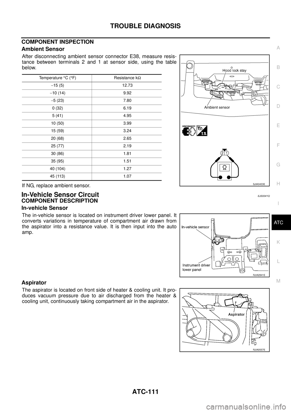
The in-vehicle sensor is located on instrument driver lower panel. It
converts variations in temperature of compartment air drawn from
the aspirator into a resistance value. It is then input into the auto
amp.
Aspirator
The aspirator is located on front side of heater & cooling unit. It pro-
duces vacuum pressure due to air discharged from the heater &
cooling unit, continuously taking compartment air in the aspirator.
Temperature °C (°F) Resistance kΩ
−15 (5) 12.73
−10 (14) 9.92
−5 (23) 7.80
0 (32) 6.19
5 (41) 4.95
10 (50) 3.99
15 (59) 3.24
20 (68) 2.65
25 (77) 2.19
30 (86) 1.81
35 (95) 1.51
40 (104) 1.27
45 (113) 1.07
SJIA0433E
RJIA2841E
RJIA0557E
Page 3300 of 4555
ATC-122
IN-VEHICLE SENSOR
IN-VEHICLE SENSORPFP:27720
Removal and InstallationEJS004GB
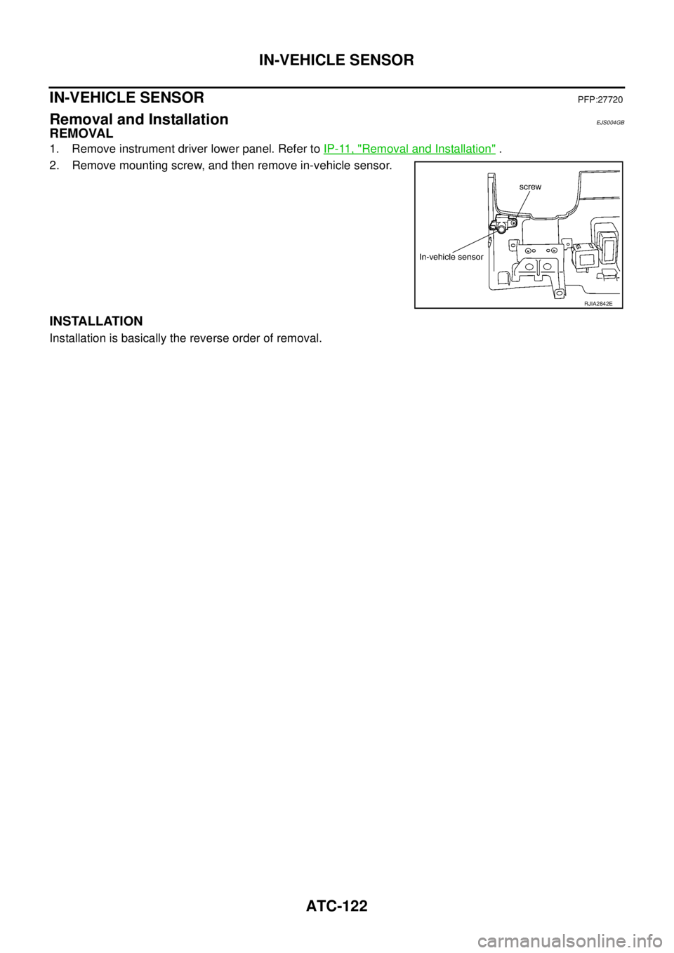
REMOVAL
1. Remove instrument driver lower panel. Refer to IP-11, "Removal and Installation" .
2. Remove mounting screw, and then remove in-vehicle sensor.
INSTALLATION
Installation is basically the reverse order of removal.
RJIA2842E
![NISSAN X-TRAIL 2005 Service Repair Manual BRC-118
[ESP/TCS/ABS]
ESP/TCS/ABS CONTROL UNIT
ESP/TCS/ABS CONTROL UNITPFP:47660
Removal and InstallationEFS001B0
REMOVAL
1. Remove the glove box. Refer to IP-3.
2. Remove the instrument lower panel](/manual-img/5/57403/w960_57403-3165.png "NISSAN X-TRAIL 2005 Service Repair Manual BRC-118
[ESP/TCS/ABS]
ESP/TCS/ABS CONTROL UNIT
ESP/TCS/ABS CONTROL UNITPFP:47660
Removal and InstallationEFS001B0
REMOVAL
1. Remove the glove box. Refer to IP-3.
2. Remove the instrument lower panel")
![NISSAN X-TRAIL 2005 Service Repair Manual ESP OFF SWITCH
BRC-121
[ESP/TCS/ABS]
C
D
E
G
H
I
J
K
L
MA
B
BRC
ESP OFF SWITCHPFP:25145
Removal and InstallationEFS001CQ
REMOVAL
1. Remove the instrument driver lower panel. Refer to IP-13,
"Instrum](/manual-img/5/57403/w960_57403-3168.png "NISSAN X-TRAIL 2005 Service Repair Manual ESP OFF SWITCH
BRC-121
[ESP/TCS/ABS]
C
D
E
G
H
I
J
K
L
MA
B
BRC
ESP OFF SWITCHPFP:25145
Removal and InstallationEFS001CQ
REMOVAL
1. Remove the instrument driver lower panel. Refer to IP-13,
\"Instrum")