Page 2113 of 4555
![NISSAN X-TRAIL 2005 Service Repair Manual FUEL LEVEL SENSOR UNIT, FUEL FILTER AND FUEL PUMP ASSEMBLY
FL-7
[QR]
C
D
E
F
G
H
I
J
K
L
MA
FL
a. Removal of main fuel level sensor unit, fuel filter and fuel pump
assembly:
i. Raise main fuel level](/manual-img/5/57403/w960_57403-2112.png "NISSAN X-TRAIL 2005 Service Repair Manual FUEL LEVEL SENSOR UNIT, FUEL FILTER AND FUEL PUMP ASSEMBLY
FL-7
[QR]
C
D
E
F
G
H
I
J
K
L
MA
FL
a. Removal of main fuel level sensor unit, fuel filter and fuel pump
assembly:
i. Raise main fuel level")
FUEL LEVEL SENSOR UNIT, FUEL FILTER AND FUEL PUMP ASSEMBLY
FL-7
[QR]
C
D
E
F
G
H
I
J
K
L
MA
FL
a. Removal of main fuel level sensor unit, fuel filter and fuel pump
assembly:
i. Raise main fuel level sensor unit, fuel filter and fuel pump
assembly, and disconnect jet pump.
ii. Leave jet pump on fuel tank with fuel hose.
CAUTION:
Do not disconnect jet pump and fuel hose.
iii. If necessary, remove chamber from the bottom of fuel tank by
sliding toward the rear of the vehicle.
b. Removal of sub fuel level sensor unit:
i. Raise and release sub fuel level sensor unit to remove.
ii. If necessary, remove jet pump inlet from the bottom of fuel tank by pinching tabs.
CAUTION:
Do not separate jet pump inlet and fuel hose.
INSPECTION AFTER REMOVAL
Make sure that fuel pump strainer is free from foreign materials. If any are found, remove them.
INSTALLATION
Note the following, and install in the reverse order of removal.
Chamber and Jet Pump
When installing chamber and jet pump, insert them fully until a click
sound of full stopper engagement is heard (Ditto for jet pump inlet).
Main and Sub Fuel Level Sensor Unit
1. Install seal packing to fuel tank without any twist.
2. Face fuel level sensor unit, fuel filter and fuel pump assembly as
shown in the figure, and install it to fuel tank. (Figure shows left
side of fuel tank.)
CAUTION:
Do not bend float arm during installing.
NOTE:
On right side of fuel tank, there are three carved lines on fuel
tank. Set mating mark between two outer carved lines.
3. Tighten rock ring with rock ring wrench (commercial service tool).
CAUTION:
Install rock ring horizontally.
Quick Connector
Connect quick connector as follows:
1. Check the connection for damage and foreign materials.
KBIA0281E
KBIA0302E
KBIA0282E
Page 2114 of 4555
![NISSAN X-TRAIL 2005 Service Repair Manual FL-8
[QR]
FUEL LEVEL SENSOR UNIT, FUEL FILTER AND FUEL PUMP ASSEMBLY
2. Align the connector with the tube, then insert the connector straight into the tube until a click sound is
heard.
3. After con](/manual-img/5/57403/w960_57403-2113.png "NISSAN X-TRAIL 2005 Service Repair Manual FL-8
[QR]
FUEL LEVEL SENSOR UNIT, FUEL FILTER AND FUEL PUMP ASSEMBLY
2. Align the connector with the tube, then insert the connector straight into the tube until a click sound is
heard.
3. After con")
FL-8
[QR]
FUEL LEVEL SENSOR UNIT, FUEL FILTER AND FUEL PUMP ASSEMBLY
2. Align the connector with the tube, then insert the connector straight into the tube until a click sound is
heard.
3. After connecting, make sure that the connection is secure by following method.
�Visually confirm that the two tabs are connected to the connector.
�Pull the tube and the connector to make sure they are
securely connected.
Inspection Hole Cover
1. Install inspection hole covers with the front mark (arrow) facing front of the vehicle.
2. Lock clips by turning counterclockwise by 90 degrees.
INSPECTION AFTER INSTALLATION
Use the following procedure to check for fuel leaks.
1. Turn ignition switch “ON” (with engine stopped), then check connections for leaks by applying fuel pres-
sure to fuel piping.
2. Start engine and let it idle and make sure there are no fuel leaks at the fuel system connections.
Disassembly and AssemblyEBS00KOV
CAUTION:
Sub fuel level sensor unit cannot be disassembled and should be replaced as a unit.
DISASSEMBLY
1. Separate fuel pump and bracket from fuel filter as follows:
PBIC1653E
1. Fuel filter 2. O-ring 3. Clip
4. Pressure regulator 5. O-ring 6. Fuel level sensor unit
7. Bracket 8. Rubber 9. Fuel pump
10. Packing
PBIC2259E
Page 2115 of 4555
![NISSAN X-TRAIL 2005 Service Repair Manual FUEL LEVEL SENSOR UNIT, FUEL FILTER AND FUEL PUMP ASSEMBLY
FL-9
[QR]
C
D
E
F
G
H
I
J
K
L
MA
FL
a. Using a screwdriver, separate the snap fit portion of bracket in
numerical order as shown in the fig](/manual-img/5/57403/w960_57403-2114.png "NISSAN X-TRAIL 2005 Service Repair Manual FUEL LEVEL SENSOR UNIT, FUEL FILTER AND FUEL PUMP ASSEMBLY
FL-9
[QR]
C
D
E
F
G
H
I
J
K
L
MA
FL
a. Using a screwdriver, separate the snap fit portion of bracket in
numerical order as shown in the fig")
FUEL LEVEL SENSOR UNIT, FUEL FILTER AND FUEL PUMP ASSEMBLY
FL-9
[QR]
C
D
E
F
G
H
I
J
K
L
MA
FL
a. Using a screwdriver, separate the snap fit portion of bracket in
numerical order as shown in the figure.
CAUTION:
Put cloth or similar one on the edge of screwdriver not to
damage the inserted portion.
b. Pull out fuel pump, and disconnect harness connector.
2. Separate fuel filter and fuel level sensor unit as follows:
a. Fit a used O-ring into space between fuel level sensor unit and
fuel filter to release tabs.
NOTE:
For reference when reassembling, put a mating mark on outer
edges of fuel level sensor unit and fuel filter with some means
which cannot be erased by fuel.
b. Insert screwdriver to the gap between fuel filter and fuel level
sensor unit to separate them.
CAUTION:
Put cloth or similar one on the edge of screwdriver not to
damage the inserted portion.
3. Remove pressure regulator from fuel filter as follows:
a. Open and remove the clip.
b. Pull pressure regulator straight out during removal.
CAUTION:
�Avoid impacts such as falling during removal.
�Do not disassemble or adjust.
ASSEMBLY
Note the following, and assemble in the reverse order of disassembly.
Fuel Filter and Fuel Pump
�Install fuel filter and fuel pump with the tabs aligned, make sure a click sound of secure engagement is
heard.
�Securely connect harness connector of fuel pump.
Pressure Regulator
Install pressure regulator as follows:
1. Install O-ring.
CAUTION:
�Do not reuse O-ring. Replace it with a new one.
�Handle O-ring with bare hands. Do not wear gloves.
PBIC0242E
PBIC0243E
PBIC0244E
Page 2116 of 4555
FL-10
[QR]
FUEL LEVEL SENSOR UNIT, FUEL FILTER AND FUEL PUMP ASSEMBLY
�Visually check O-ring, mounting parts and mating parts for foreign materials and flaws.
�Before installing, lubricate new engine oil.
�To avoid damage, do not apply an excessive force (pulling or stretching).
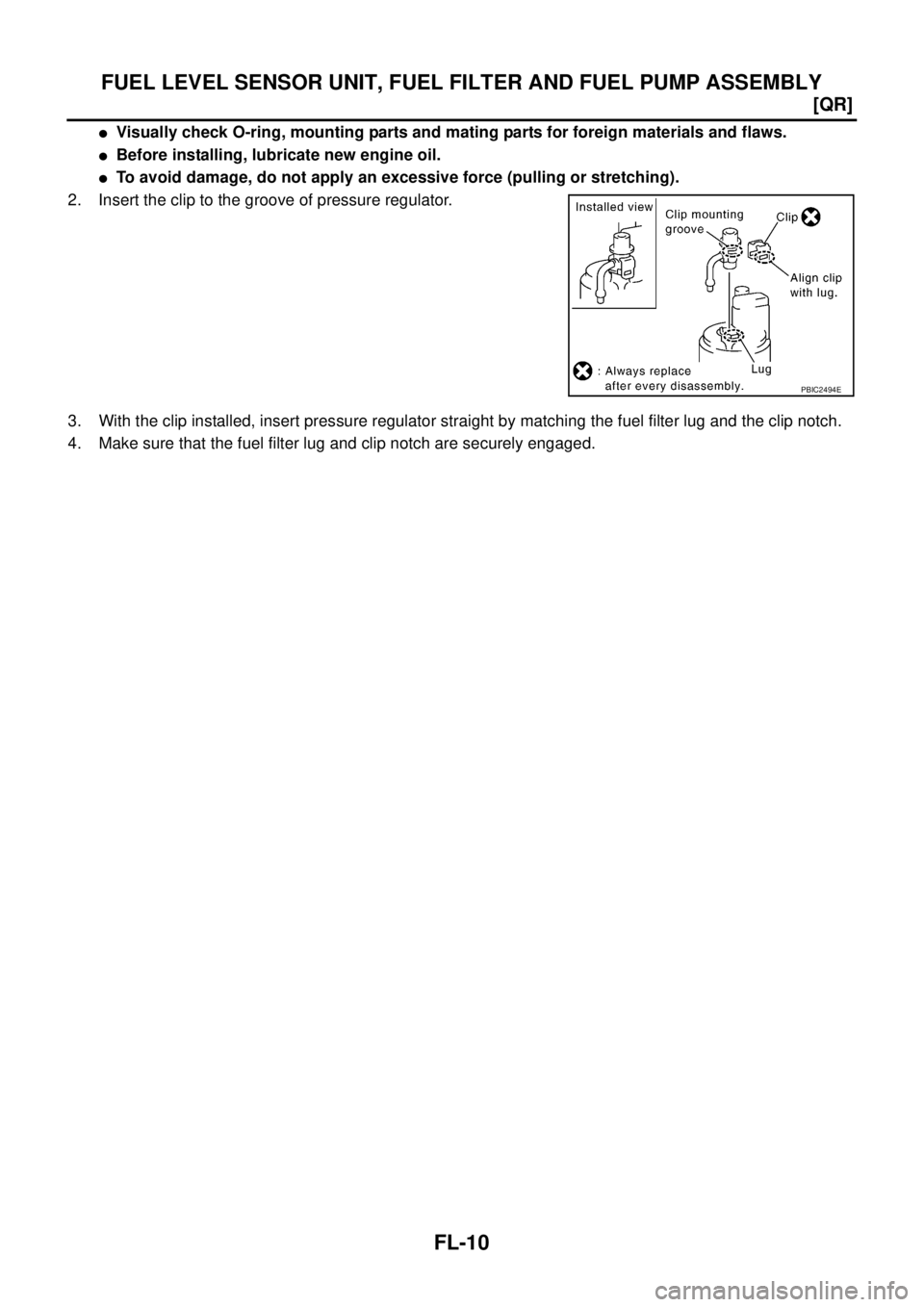
2. Insert the clip to the groove of pressure regulator.
3. With the clip installed, insert pressure regulator straight by matching the fuel filter lug and the clip notch.
4. Make sure that the fuel filter lug and clip notch are securely engaged.
PBIC2494E
Page 2117 of 4555
FUEL TANK
FL-11
[QR]
C
D
E
F
G
H
I
J
K
L
MA
FL
FUEL TANKPFP:17202
Removal and InstallationEBS00KOW
REMOVAL
WARNING:
Be sure to read “General Precautions” when working on the fuel system. Refer to FL-3, "
General Pre-
cautions" .
1. Perform the steps 1 to 7 of “REMOVAL” in “ FUEL LEVEL SENSOR UNIT, FUEL FILTER AND FUEL
PUMP ASSEMBLY”. Refer to FL-4, "
REMOVAL" .
2. Drain fuel more from fuel tank if necessary.
CAUTION:
Because fuel tank forwardly inclines and becomes unstable when installing/removing, fuel should
be drained if found the remaining quantity.
3. Remove exhaust center tube and insulator. Refer to EX-2, "
EXHAUST SYSTEM" .
4. Remove propeller shaft. (4WD models) Refer to PR-3, "
REAR PROPELLER SHAFT" .
PBIC0246E
1. Fuel filler cap 2. Grommet 3. Fuel filler tube
4. Vent hose 5. Vent tube 6. Fuel tank
7. Fuel filler hose 8. Fuel tank band 9. Fuel tank protector
Page 2121 of 4555
PREPARATION
FL-15
[YD22DDTi]
C
D
E
F
G
H
I
J
K
L
MA
FL
[YD22DDTi]PREPARATIONPFP:00002
Commercial Service ToolsEBS00BKG
Tool nameDescription
Fuel filter wrench Removing fuel filter
Fuel tank lock ring wrench Removing and installing fuel tank lock ring
PBIC0519E
ZZA0122D
Page 2123 of 4555
![NISSAN X-TRAIL 2005 Service Repair Manual FUEL FILTER
FL-17
[YD22DDTi]
C
D
E
F
G
H
I
J
K
L
MA
FL
FUEL FILTERPFP:16400
Removal and InstallationEBS00BLA
REMOVAL
1. Remove air duct, air cleaner case and mass air flow sensor assembly. Refer to](/manual-img/5/57403/w960_57403-2122.png "NISSAN X-TRAIL 2005 Service Repair Manual FUEL FILTER
FL-17
[YD22DDTi]
C
D
E
F
G
H
I
J
K
L
MA
FL
FUEL FILTERPFP:16400
Removal and InstallationEBS00BLA
REMOVAL
1. Remove air duct, air cleaner case and mass air flow sensor assembly. Refer to")
FUEL FILTER
FL-17
[YD22DDTi]
C
D
E
F
G
H
I
J
K
L
MA
FL
FUEL FILTERPFP:16400
Removal and InstallationEBS00BLA
REMOVAL
1. Remove air duct, air cleaner case and mass air flow sensor assembly. Refer to EM-142, "AIR CLEANER
AND AIR DUCT" .
2. Remove fuel filter protector.
3. Disconnect fuel hoses at fuel filter bracket.
CAUTION:
Plug the pipe to prevent fuel from draining.
4. Remove fuel filter with fuel filter bracket.
CAUTION:
Do not splash fuel during removal. If fuel is splashed,
immediately wipe it off.
5. Using band-type fuel filter wrench (commercial service tool),
remove fuel filter.
6. Turn fuel filter upside down to drain fuel.
7. Remove drain plug from fuel filter.
INSTALLATION
Note the following, and install in the reverse order of removal.
�Replace O-ring on drain plug with new one.
�Screw the fuel filter by hand until packing contacts sealing surface of bracket. Then tighten it by turning
approximately 2/3 turn.
�After installation, bleed air from fuel line. Refer to FL-18, "Air Bleeding" .
INSPECTION AFTER INSTALLATION
Make sure there is no fuel leakage at connections in the following steps.
�Start the engine and rev it up and make sure there is no fuel leakage at connections.
PBIC2501E
SBIA0135E
SBIA0136E
Drain plug
: 4.9 N·m (0.5 kg-m, 43 in-lb)
Page 2124 of 4555
![NISSAN X-TRAIL 2005 Service Repair Manual FL-18
[YD22DDTi]
FUEL FILTER
Air BleedingEBS00BLB
After fuel filter is replaced and after fuel system components are
removed/installed, bleed air from fuel line as follows:
�Move priming pump up and](/manual-img/5/57403/w960_57403-2123.png "NISSAN X-TRAIL 2005 Service Repair Manual FL-18
[YD22DDTi]
FUEL FILTER
Air BleedingEBS00BLB
After fuel filter is replaced and after fuel system components are
removed/installed, bleed air from fuel line as follows:
�Move priming pump up and")
FL-18
[YD22DDTi]
FUEL FILTER
Air BleedingEBS00BLB
After fuel filter is replaced and after fuel system components are
removed/installed, bleed air from fuel line as follows:
�Move priming pump up and down to bleed air from fuel path.
�When air is bled, pumping of priming pump becomes heavy stop
operation at that time.
�Crank engine until it starts. Do not crank engine for more than
30 seconds.
�If engine does not start, stop cranking and repeat step 1 above.
�If engine does not operate smoothly after it has started, race it
two or three times.
�If air cannot be bled easily (pumping of priming pump does not
become heavy), disconnect feed-side of hose between fuel filter and electronically controlled fuel pump.
After that, operate priming pump and confirm that fuel comes out.
CAUTION:
Prepare a tray to collect fuel. Prevent fuel from adhering to rubber parts, especially the engine
mounting insulator.
Draining Water from Fuel FilterEBS00MRU
1. Prepare a tray at the drain hose open end.
2. Loosen drain cock, and operate priming pump to drain water
from fuel filter.
CAUTION:
�Water in filter is drained with fuel. Prepare larger capacity
pan than fuel filter volume.
�Drained water is mixed with fuel. Prevent fuel from adher-
ing to rubber parts such as engine mounting insulator.
3. After draining, close drain cock by hand.
CAUTION:
If drain cock is tightened excessively, it may be damaged
and fuel will leak. Do not use tools to tighten drain cock.
4. Bleed air in fuel piping. Refer to FL-18, "
Air Bleeding" .
5. Start engine and make sure there is no fuel leakage.
SBIA0137E
SBIA0138E
![NISSAN X-TRAIL 2005 Service Repair Manual FUEL TANK
FL-11
[QR]
C
D
E
F
G
H
I
J
K
L
MA
FL
FUEL TANKPFP:17202
Removal and InstallationEBS00KOW
REMOVAL
WARNING:
Be sure to read “General Precautions” when working on the fuel system. Refer t](/manual-img/5/57403/w960_57403-2116.png "NISSAN X-TRAIL 2005 Service Repair Manual FUEL TANK
FL-11
[QR]
C
D
E
F
G
H
I
J
K
L
MA
FL
FUEL TANKPFP:17202
Removal and InstallationEBS00KOW
REMOVAL
WARNING:
Be sure to read “General Precautions” when working on the fuel system. Refer t")
![NISSAN X-TRAIL 2005 Service Repair Manual PREPARATION
FL-15
[YD22DDTi]
C
D
E
F
G
H
I
J
K
L
MA
FL
[YD22DDTi]PREPARATIONPFP:00002
Commercial Service ToolsEBS00BKG
Tool nameDescription
Fuel filter wrench Removing fuel filter
Fuel tank lock rin](/manual-img/5/57403/w960_57403-2120.png "NISSAN X-TRAIL 2005 Service Repair Manual PREPARATION
FL-15
[YD22DDTi]
C
D
E
F
G
H
I
J
K
L
MA
FL
[YD22DDTi]PREPARATIONPFP:00002
Commercial Service ToolsEBS00BKG
Tool nameDescription
Fuel filter wrench Removing fuel filter
Fuel tank lock rin")