Page 3057 of 4555
CAN COMMUNICATION
BRC-9
[ABS]
C
D
E
G
H
I
J
K
L
MA
B
BRC
*: YD engine models only
TYPE 3
System diagram
Input/output signal chart
T: Transmit R: Receive A/C compressor feedback signal T R
ABS warning lamp signal T R
Accelerator pedal position signal T R
Engine coolant temperature signal T R
Engine speed signal T R R
MI signal T R
Parking brake switch signalRT
Stop lamp switch signal T R
Vehicle speed signalTRR
RT
ASCD SET lamp signal T R
ASCD CRUISE lamp signal T R
Stop lamp switch signal T R
Glow indicator lamp signal* T R
A/C switch signal* R TSignals ECMABS actuator and
electric unit
(control unit)4WD control unit Combination meter
PKIA6457E
Signals ECM TCMABS actuator
and electric unit
(control unit)4WD control
unitCombination
meter
4WD mode indicator lamp signalTR
4WD warning lamp signalTR
A/C compressor feedback signal TR
A/T position indicator lamp signal T R
A/T self-diagnosis signal R T
ABS warning lamp signal T R
Page 3058 of 4555
BRC-10
[ABS]
CAN COMMUNICATION
TYPE 7/TYPE 8
System diagram
Input/output signal chart
T: Transmit R: Receive Accelerator pedal position signal T R
Closed throttle position signal T R
Engine A/T integrated control signalTR
RT
Engine coolant temperature signal TR
Engine speed signal T R R
MI signal TR
O/D OFF indicator signal T R
Output shaft revolution signal R T
Overdrive control switch signal R T
P·N range signal R T
Parking brake switch signalRT
Stop lamp switch signalRT
TR
Vehicle speed signalTRR
RT
Wide open throttle position signal T R
ASCD SET lamp signal TR
ASCD CRUISE lamp signal TR Signals ECM TCMABS actuator
and electric unit
(control unit)4WD control
unitCombination
meter
SKIA9999E
Signals ECM ABS actuator and electric unit (control unit) Combination meter
A/C compressor feedback signal T R
ABS warning lamp signal T R
Engine coolant temperature signal T R
Engine speed signal T R
Page 3105 of 4555
CAN COMMUNICATION
BRC-57
[ESP/TCS/ABS]
C
D
E
G
H
I
J
K
L
MA
B
BRC
*1: YD engine models only
*2: QR engine models only
TYPE 6
System diagram
Input/output signal chart
T: Transmit R: Receive A/C switch signal*
1RT
ABS warning lamp signal T R
Accelerator pedal position signal T R R
Brake warning lamp signal T R
Engine coolant temperature signal TR
Engine speed signal T R R R
ESP OFF indicator lamp signal T R
Glow indicator lamp signal*1 TR
MI signal TR
Stop lamp switch signal T R
Vehicle speed signalTRR
RT
SLIP indicator lamp signal T R
Parking brake switch signalRT
Steering angle sensor signal R T
ASCD SET lamp signal TR
ASCD CRUISE lamp signal TR Signals ECMESP/TCS/ABS
control unitSteering angle
sensor4WD control
unitCombination
meter
PKIA9635E
Signals ECM TCMESP/TCS/
ABS control
unitSteering
angle sensor4WD control
unitCombination
meter
4WD mode indicator lamp signalTR
4WD warning lamp signalTR
A/C compressor feedback signal TR
Page 3106 of 4555
BRC-58
[ESP/TCS/ABS]
CAN COMMUNICATION
TYPE 9
System diagram
A/T position indicator lamp signal T R R
A/T self-diagnosis signal R T
ABS warning lamp signal T R
Accelerator pedal position signal T R R
Brake warning lamp signal T R
Closed throttle position signal T R
Engine and A/T integratedTR
RT
Engine coolant temperature signal TR
Engine speed signal T R R R
ESP OFF indicator lamp signal T R
MI signal TR
O/D OFF indicator signal T R
Output shaft revolution signal R T
Overdrive control switch signal R T
P·N range signal R T
SLIP indicator lamp signal T R
Steering angle sensor signal R T
Stop lamp switch signalRT
TR
Vehicle speed signalTRR
RT
Parking brake switch signalRT
Wide open throttle position signal T R
ASCD SET lamp signal TR
ASCD CRUISE lamp signal TR Signals ECM TCMESP/TCS/
ABS control
unitSteering
angle sensor4WD control
unitCombination
meter
PKIC0343E
Page 3107 of 4555
CAN COMMUNICATION
BRC-59
[ESP/TCS/ABS]
C
D
E
G
H
I
J
K
L
MA
B
BRC
Input/output signal chart
T: Transmit R: Receive
Signals ECM ESP/TCS/ABS control unit Steering angle sensor Combination meter
A/C switch signal RT
ABS warning lamp signal T R
Accelerator pedal position signal T R
Brake warning lamp signal T R
Engine coolant temperature signal TR
Engine speed signal T R R
ESP OFF indicator lamp signal T R
Glow indicator lamp signal TR
MI signal TR
Vehicle speed signalTR
RT
SLIP indicator lamp signal T R
Steering angle sensor signal R T
ASCD SET lamp signal TR
ASCD CRUISE lamp signal TR
Page 3207 of 4555

AIR CONDITIONER CONTROL
ATC-29
C
D
E
F
G
H
I
K
L
MA
B
AT C
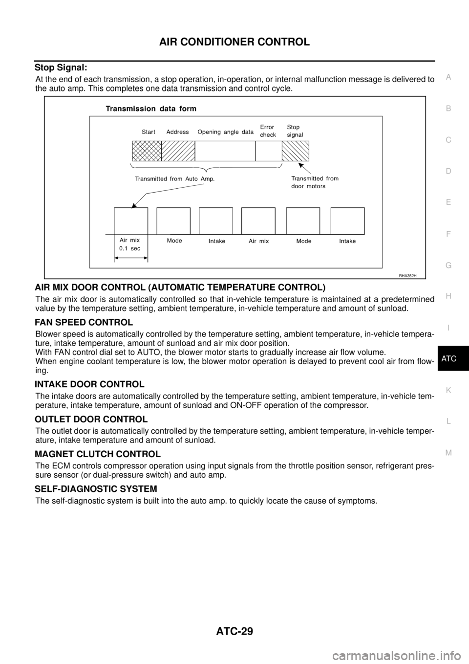
Stop Signal:
At the end of each transmission, a stop operation, in-operation, or internal malfunction message is delivered to
the auto amp. This completes one data transmission and control cycle.
AIR MIX DOOR CONTROL (AUTOMATIC TEMPERATURE CONTROL)
The air mix door is automatically controlled so that in-vehicle temperature is maintained at a predetermined
value by the temperature setting, ambient temperature, in-vehicle temperature and amount of sunload.
FAN SPEED CONTROL
Blower speed is automatically controlled by the temperature setting, ambient temperature, in-vehicle tempera-
ture, intake temperature, amount of sunload and air mix door position.
With FAN control dial set to AUTO, the blower motor starts to gradually increase air flow volume.
When engine coolant temperature is low, the blower motor operation is delayed to prevent cool air from flow-
ing.
INTAKE DOOR CONTROL
The intake doors are automatically controlled by the temperature setting, ambient temperature, in-vehicle tem-
perature, intake temperature, amount of sunload and ON-OFF operation of the compressor.
OUTLET DOOR CONTROL
The outlet door is automatically controlled by the temperature setting, ambient temperature, in-vehicle temper-
ature, intake temperature and amount of sunload.
MAGNET CLUTCH CONTROL
The ECM controls compressor operation using input signals from the throttle position sensor, refrigerant pres-
sure sensor (or dual-pressure switch) and auto amp.
SELF-DIAGNOSTIC SYSTEM
The self-diagnostic system is built into the auto amp. to quickly locate the cause of symptoms.
RHA352H
Page 3234 of 4555
ATC-56
TROUBLE DIAGNOSIS
20 L/W Power supply for IGN2 ON - Battery voltage
21 GY Water temperature sensor ONAt idle [after warming up,
approx. 80°C (176°F)]
CAUTION:
The waveforms vary depend-
ing on coolant temperature
22 LG/BRear window defogger ON
signalONRear window defogger: ON Approx. 0
Rear window defogger: OFF Approx. 12
23 B/WRear window defogger feed
back signalONRear window defogger: ON Approx. 12
Rear window defogger: OFF Approx. 0
24 B/Y Sensor ground ON - Approx. 0
25 BR/Y Intake sensor - - -
28 YPower supply for ambient
temperature displayON - Approx. 5
30 PU Compressor feed back signal ON-Approx. 0
When refrigerant pressure sen-
sor connector is disconnectedApprox. 5 Te r m i -
nal No.Wire
colorItemIgnition
switchConditionVoltage
(V)
SKIA0056J
Page 3262 of 4555

ATC-84
TROUBLE DIAGNOSIS
Starting Fan Speed Control
Start Up from COLD SOAK Condition (Automatic mode)
In a cold start up condition where the engine coolant temperature is below 56°C (133°F), the blower will not
operate for a short period of time (up to 150 seconds). The exact start delay time varies depending on the
ambient and engine coolant temperature.
In the most extreme case (very low ambient) the blower starting delay will be 150 seconds as described
above. After this delay, the blower will operate at low speed until the engine coolant temperature rises above
56°C (133°F), and then the blower speed will increase to the objective speed.
Start Up from Usual or HOT SOAK Condition (Automatic mode)
The blower will begin operation momentarily after the A/C switch is pushed. The blower speed will gradually
rise to the objective speed over a time period of 3 seconds or less (actual time depends on the objective
blower speed).
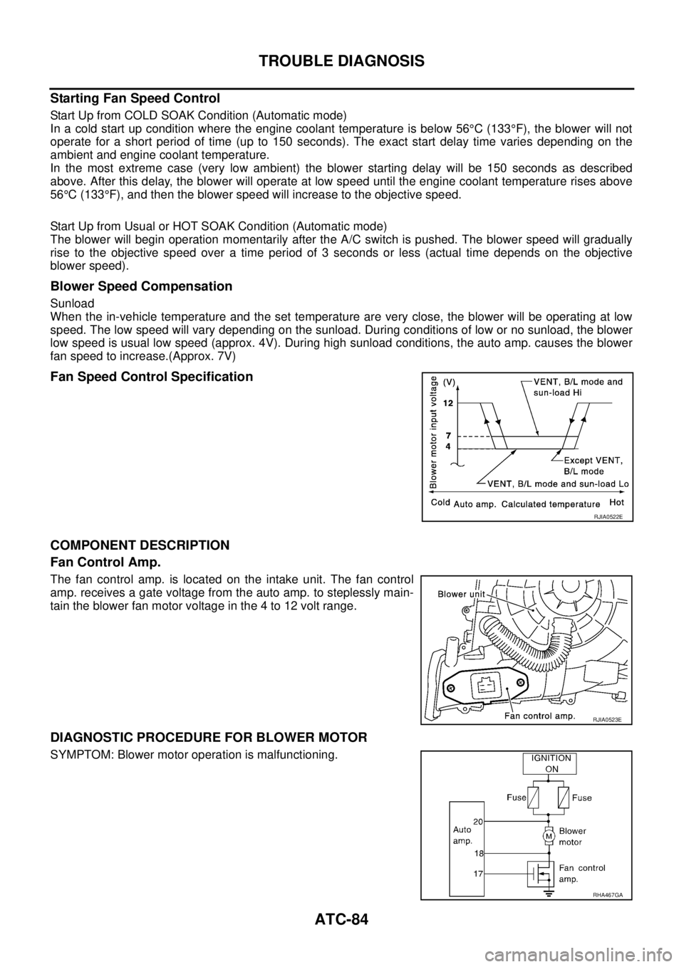
Blower Speed Compensation
Sunload
When the in-vehicle temperature and the set temperature are very close, the blower will be operating at low
speed. The low speed will vary depending on the sunload. During conditions of low or no sunload, the blower
low speed is usual low speed (approx. 4V). During high sunload conditions, the auto amp. causes the blower
fan speed to increase.(Approx. 7V)
Fan Speed Control Specification
COMPONENT DESCRIPTION
Fan Control Amp.
The fan control amp. is located on the intake unit. The fan control
amp. receives a gate voltage from the auto amp. to steplessly main-
tain the blower fan motor voltage in the 4 to 12 volt range.
DIAGNOSTIC PROCEDURE FOR BLOWER MOTOR
SYMPTOM: Blower motor operation is malfunctioning.
RJIA0522E
RJIA0523E
RHA467GA