Page 958 of 4555
EC-554
[QR (WITHOUT EURO-OBD)]
ENGINE CONTROL SYSTEM
TYPE 5
System Diagram
Input/output Signal Chart
T: Transmit R: Receive Engine coolant temperature signal TR
Engine speed signal T R R
MI signal TR
O/D OFF indicator signal T R
Output shaft revolution signal R T
Overdrive control switch signal R T
P·N range signal R T
Parking brake switch signalRT
Stop lamp switch signalRT
TR
Vehicle speed signalTRR
RT
Wide open throttle position signal T R
ASCD SET lamp signal TR
ASCD CRUISE lamp signal TR Signals ECM TCMABS actuator
and electric unit
(control unit)4WD control
unitCombination
meter
PKIA6459E
Signals ECMESP/TCS/ABS
control unitSteering angle
sensor4WD control
unitCombination
meter
4WD mode indicator lamp signalTR
4WD warning lamp signalTR
A/C compressor feedback signal TR
ABS warning lamp signal T R
Accelerator pedal position signal T R R
Brake warning lamp signal T R
Engine coolant temperature signal TR
Page 959 of 4555
ENGINE CONTROL SYSTEM
EC-555
[QR (WITHOUT EURO-OBD)]
C
D
E
F
G
H
I
J
K
L
MA
EC
TYPE 6
System Diagram
Input/output Signal Chart
T: Transmit R: Receive Engine speed signal T R R R
ESP OFF indicator lamp signal T R
MI signal TR
Stop lamp switch signal T R
Vehicle speed signalTRR
RT
SLIP indicator lamp signal T R
Parking brake switch signalRT
Steering angle sensor signal R T
ASCD SET lamp signal TR
ASCD CRUISE lamp signal TR Signals ECMESP/TCS/ABS
control unitSteering angle
sensor4WD control
unitCombination
meter
PKIA6460E
Signals ECM TCMESP/TCS/
ABS control
unitSteering
angle sensor4WD control
unitCombination
meter
4WD mode indicator lamp signalTR
4WD warning lamp signalTR
A/C compressor feedback signal TR
A/T position indicator lamp signal T R R
A/T self-diagnosis signal R T
ABS warning lamp signal T R
Accelerator pedal position signal T R R
Brake warning lamp signal T R
Closed throttle position signal T R
Engine and A/T integratedTR
RT
Page 960 of 4555
EC-556
[QR (WITHOUT EURO-OBD)]
ENGINE CONTROL SYSTEM
TYPE 7
System diagram
Input/output signal chart
T: Transmit R: Receive Engine coolant temperature signal TR
Engine speed signal T R R R
ESP OFF indicator lamp signal T R
MI signal TR
O/D OFF indicator signal T R
Output shaft revolution signal R T
Overdrive control switch signal R T
P·N range signal R T
SLIP indicator lamp signal T R
Steering angle sensor signal R T
Stop lamp switch signalRT
TR
Vehicle speed signalTRR
RT
Parking brake switch signalRT
Wide open throttle position signal T R
ASCD SET lamp signal TR
ASCD CRUISE lamp signal TR Signals ECM TCMESP/TCS/
ABS control
unitSteering
angle sensor4WD control
unitCombination
meter
SKIA9999E
Signals ECM ABS actuator and electric unit (control unit) Combination meter
A/C compressor feedback signal T R
ABS warning lamp signal T R
Engine coolant temperature signal T R
Engine speed signal T R
MI signal T R
Page 997 of 4555
TROUBLE DIAGNOSIS
EC-593
[QR (WITHOUT EURO-OBD)]
C
D
E
F
G
H
I
J
K
L
MA
EC
Circuit DiagramEBS010XA
TBWB0691E
Page 1029 of 4555
POWER SUPPLY AND GROUND CIRCUIT
EC-625
[QR (WITHOUT EURO-OBD)]
C
D
E
F
G
H
I
J
K
L
MA
EC
POWER SUPPLY AND GROUND CIRCUITPFP:24110
Wiring DiagramEBS010XM
TBWA0594E
Page 1031 of 4555
POWER SUPPLY AND GROUND CIRCUIT
EC-627
[QR (WITHOUT EURO-OBD)]
C
D
E
F
G
H
I
J
K
L
MA
EC
4. CHECK GROUND CONNECTIONS
1. Turn ignition switch OFF.
2. Loosen and retighten three ground screws on the body.
Refer to EC-632, "
Ground Inspection" .
OK or NG
OK >> GO TO 5.
NG >> Repair or replace ground connections.
5. CHECK ECM GROUND CIRCUIT FOR OPEN AND SHORT-I
1. Turn ignition switch OFF.
2. Disconnect ECM harness connector.
3. Check harness continuity between ECM terminals 1, 115, 116 and ground.
Refer to Wiring Diagram.
4. Also check harness for short to power.
OK or NG
OK >> GO TO 6.
NG >> Repair open circuit or short to power in harness or connectors.
PBIB2021E
Continuity should exist.
Page 1032 of 4555
![NISSAN X-TRAIL 2005 Service Repair Manual EC-628
[QR (WITHOUT EURO-OBD)]
POWER SUPPLY AND GROUND CIRCUIT
6. CHECK ECM POWER SUPPLY CIRCUIT-II
1. Disconnect ECM relay.
2. Check voltage between ECM relay terminals 1, 6 and ground
with CONSULT](/manual-img/5/57403/w960_57403-1031.png "NISSAN X-TRAIL 2005 Service Repair Manual EC-628
[QR (WITHOUT EURO-OBD)]
POWER SUPPLY AND GROUND CIRCUIT
6. CHECK ECM POWER SUPPLY CIRCUIT-II
1. Disconnect ECM relay.
2. Check voltage between ECM relay terminals 1, 6 and ground
with CONSULT")
EC-628
[QR (WITHOUT EURO-OBD)]
POWER SUPPLY AND GROUND CIRCUIT
6. CHECK ECM POWER SUPPLY CIRCUIT-II
1. Disconnect ECM relay.
2. Check voltage between ECM relay terminals 1, 6 and ground
with CONSULT-II or tester.
OK or NG
OK >> GO TO 8.
NG >> GO TO 7.
7. DETECT MALFUNCTIONING PART
Check the following.
�Harness connectors E61, F38
�20A fuse
�Harness for open or short between ECM relay and battery
>> Repair open circuit or short to ground or short to power in harness or connectors.
8. CHECK OUTPUT SIGNAL CIRCUIT FOR OPEN AND SHORT
1. Check harness continuity between ECM terminal 111 and ECM relay terminal 2.
Refer to Wiring Diagram.
2. Also check harness for short to ground and short to power.
OK or NG
OK >> GO TO 10.
NG >> GO TO 9.
9. DETECT MALFUNCTIONING PART
Check the following.
�Harness connectors F41, M61
�Harness for open or short between ECM relay and ECM
>> Repair open circuit or short to ground or short to power in harness or connectors.
PBIB1973E
Voltage: Battery voltage
SEF420X
Continuity should exist.
Page 1034 of 4555
EC-630
[QR (WITHOUT EURO-OBD)]
POWER SUPPLY AND GROUND CIRCUIT
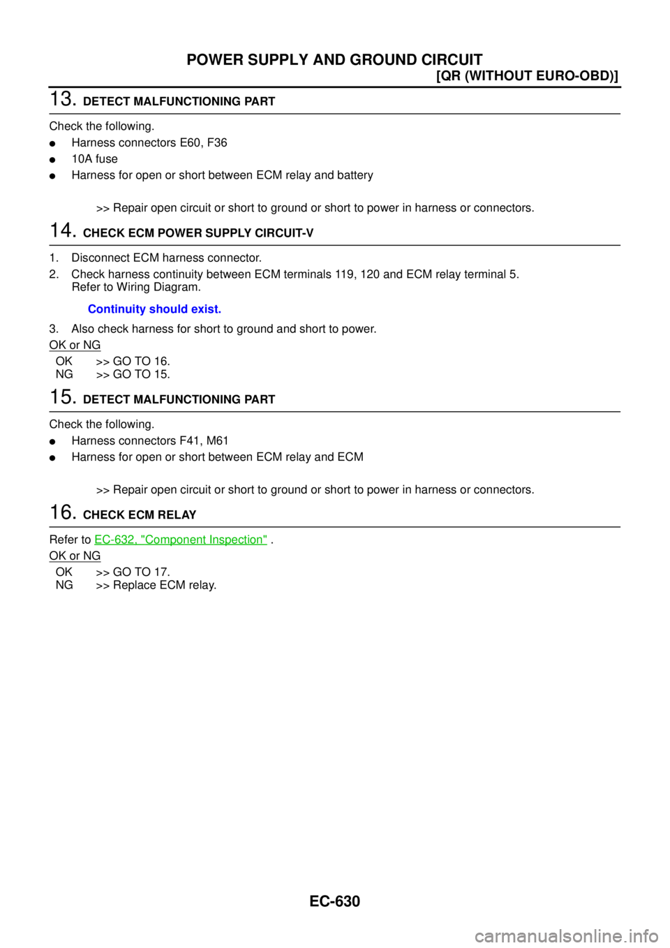
13. DETECT MALFUNCTIONING PART
Check the following.
�Harness connectors E60, F36
�10A fuse
�Harness for open or short between ECM relay and battery
>> Repair open circuit or short to ground or short to power in harness or connectors.
14. CHECK ECM POWER SUPPLY CIRCUIT-V
1. Disconnect ECM harness connector.
2. Check harness continuity between ECM terminals 119, 120 and ECM relay terminal 5.
Refer to Wiring Diagram.
3. Also check harness for short to ground and short to power.
OK or NG
OK >> GO TO 16.
NG >> GO TO 15.
15. DETECT MALFUNCTIONING PART
Check the following.
�Harness connectors F41, M61
�Harness for open or short between ECM relay and ECM
>> Repair open circuit or short to ground or short to power in harness or connectors.
16. CHECK ECM RELAY
Refer to EC-632, "
Component Inspection" .
OK or NG
OK >> GO TO 17.
NG >> Replace ECM relay.Continuity should exist.
![NISSAN X-TRAIL 2005 Service Repair Manual EC-554
[QR (WITHOUT EURO-OBD)]
ENGINE CONTROL SYSTEM
TYPE 5
System Diagram
Input/output Signal Chart
T: Transmit R: Receive Engine coolant temperature signal TR
Engine speed signal T R R
MI signal](/manual-img/5/57403/w960_57403-957.png "NISSAN X-TRAIL 2005 Service Repair Manual EC-554
[QR (WITHOUT EURO-OBD)]
ENGINE CONTROL SYSTEM
TYPE 5
System Diagram
Input/output Signal Chart
T: Transmit R: Receive Engine coolant temperature signal TR
Engine speed signal T R R
MI signal")
![NISSAN X-TRAIL 2005 Service Repair Manual ENGINE CONTROL SYSTEM
EC-555
[QR (WITHOUT EURO-OBD)]
C
D
E
F
G
H
I
J
K
L
MA
EC
TYPE 6
System Diagram
Input/output Signal Chart
T: Transmit R: Receive Engine speed signal T R R R
ESP OFF indicator](/manual-img/5/57403/w960_57403-958.png "NISSAN X-TRAIL 2005 Service Repair Manual ENGINE CONTROL SYSTEM
EC-555
[QR (WITHOUT EURO-OBD)]
C
D
E
F
G
H
I
J
K
L
MA
EC
TYPE 6
System Diagram
Input/output Signal Chart
T: Transmit R: Receive Engine speed signal T R R R
ESP OFF indicator")
![NISSAN X-TRAIL 2005 Service Repair Manual EC-556
[QR (WITHOUT EURO-OBD)]
ENGINE CONTROL SYSTEM
TYPE 7
System diagram
Input/output signal chart
T: Transmit R: Receive Engine coolant temperature signal TR
Engine speed signal T R R R
ESP OFF](/manual-img/5/57403/w960_57403-959.png "NISSAN X-TRAIL 2005 Service Repair Manual EC-556
[QR (WITHOUT EURO-OBD)]
ENGINE CONTROL SYSTEM
TYPE 7
System diagram
Input/output signal chart
T: Transmit R: Receive Engine coolant temperature signal TR
Engine speed signal T R R R
ESP OFF")
![NISSAN X-TRAIL 2005 Service Repair Manual TROUBLE DIAGNOSIS
EC-593
[QR (WITHOUT EURO-OBD)]
C
D
E
F
G
H
I
J
K
L
MA
EC
Circuit DiagramEBS010XA
TBWB0691E](/manual-img/5/57403/w960_57403-996.png "NISSAN X-TRAIL 2005 Service Repair Manual TROUBLE DIAGNOSIS
EC-593
[QR (WITHOUT EURO-OBD)]
C
D
E
F
G
H
I
J
K
L
MA
EC
Circuit DiagramEBS010XA
TBWB0691E")
![NISSAN X-TRAIL 2005 Service Repair Manual POWER SUPPLY AND GROUND CIRCUIT
EC-625
[QR (WITHOUT EURO-OBD)]
C
D
E
F
G
H
I
J
K
L
MA
EC
POWER SUPPLY AND GROUND CIRCUITPFP:24110
Wiring DiagramEBS010XM
TBWA0594E](/manual-img/5/57403/w960_57403-1028.png "NISSAN X-TRAIL 2005 Service Repair Manual POWER SUPPLY AND GROUND CIRCUIT
EC-625
[QR (WITHOUT EURO-OBD)]
C
D
E
F
G
H
I
J
K
L
MA
EC
POWER SUPPLY AND GROUND CIRCUITPFP:24110
Wiring DiagramEBS010XM
TBWA0594E")
![NISSAN X-TRAIL 2005 Service Repair Manual POWER SUPPLY AND GROUND CIRCUIT
EC-627
[QR (WITHOUT EURO-OBD)]
C
D
E
F
G
H
I
J
K
L
MA
EC
4. CHECK GROUND CONNECTIONS
1. Turn ignition switch OFF.
2. Loosen and retighten three ground screws on the b](/manual-img/5/57403/w960_57403-1030.png "NISSAN X-TRAIL 2005 Service Repair Manual POWER SUPPLY AND GROUND CIRCUIT
EC-627
[QR (WITHOUT EURO-OBD)]
C
D
E
F
G
H
I
J
K
L
MA
EC
4. CHECK GROUND CONNECTIONS
1. Turn ignition switch OFF.
2. Loosen and retighten three ground screws on the b")