Page 2740 of 4555
AT-476
[ALL]
REPAIR FOR COMPONENT PARTS
2. Remove snap ring for forward clutch.
3. Remove drive plates, driven plates, retaining plate and dish
plate for forward clutch.
4. Remove snap ring for overrun clutch with flat-bladed screw-
driver.
5. Remove drive plates, driven plates, retaining plate and dish
plate for overrun clutch.
6. Set Tool on spring retainer and remove snap ring from forward
clutch drum while compressing return springs.
CAUTION:
�Set SST directly over return springs.
�Do not expand snap ring excessively.
7. Remove spring retainer and return springs.
CAUTION:
Do not remove return springs from spring retainer.
8. Remove forward clutch piston with overrun clutch piston from
forward clutch drum by turning it.
9. Remove overrun clutch piston from forward clutch piston by
turning it.
SCIA4894E
SCIA4895E
SAT124FC
SAT125F
SAT126F
Page 2984 of 4555

RSU-6
REAR SUSPENSION ASSEMBLY
On-Vehicle Inspection and ServiceEES0007F
Check axle and suspension parts for excessive play, wear, and damage.
�Move rear wheels (RH/LH) to check abnormal free play.
�Retighten all nuts and bolts to the specified torque.
�Check strut for oil leakage and damage.
Wheel AlignmentEES0007G
DESCRIPTION
�Measure wheel alignment under unladen conditions. “Unladen conditions” means that fuel, coolant, and
lubricant are full. However, spare tyre, jack, and hand tools should be unloaded.
PRELIMINARY INSPECTION
1. Check the tyre for improper air pressure and wear.
2. Check road wheels for runout.
3. Check wheel bearing axial endplay.
4. Check strut operation.
5. Check each mounting point of axle and suspension for looseness and deformation.
6. Check each link and arm for cracks, deformation, and other damage.
7. Check the vehicle posture.
CAMBER
Camber is preset at factory and cannot be adjusted.
�If the camber is not within specification, inspect and replace any damaged or worn rear suspension parts.
TOE-IN
Measure toe-in using the following procedure.
�Always perform following procedure on a flat surface.
�Make sure that no person is in front of the vehicle before push-
ing it.
1. Bounce rear of vehicle up and down to stabilize the posture.
2. Push the vehicle straight ahead about 5 m (16 ft).
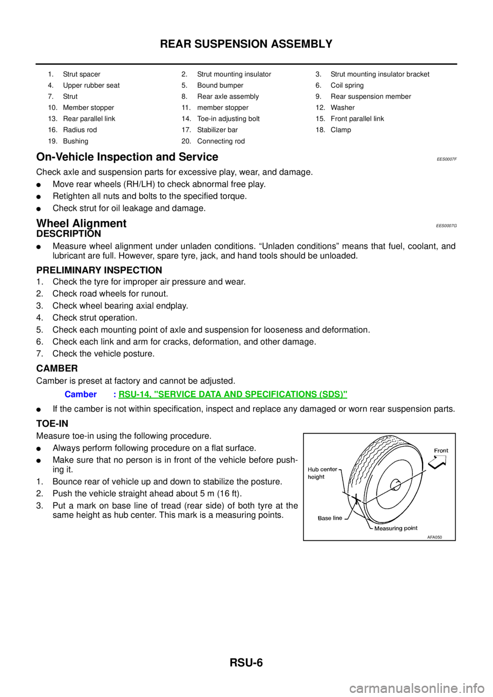
3. Put a mark on base line of tread (rear side) of both tyre at the
same height as hub center. This mark is a measuring points.
1. Strut spacer 2. Strut mounting insulator 3. Strut mounting insulator bracket
4. Upper rubber seat 5. Bound bumper 6. Coil spring
7. Strut 8. Rear axle assembly 9. Rear suspension member
10. Member stopper 11. member stopper 12. Washer
13. Rear parallel link 14. Toe-in adjusting bolt 15. Front parallel link
16. Radius rod 17. Stabilizer bar 18. Clamp
19. Bushing 20. Connecting rod
Camber : RSU-14, "SERVICE DATA AND SPECIFICATIONS (SDS)"
AFA050
Page 2995 of 4555

ROAD WHEEL
WT-3
C
D
F
G
H
I
J
K
L
MA
B
WT
ROAD WHEELPFP:40300
InspectionEES000J2
ALUMINUM WHEEL
1. Check tyres for wear and improper inflation.
2. Check wheels for deformation, cracks and other damage. If
deformed, remove wheel and check the wheel runout.
a. Remove tyre from aluminum wheel and mount on a tyre balance
machine.
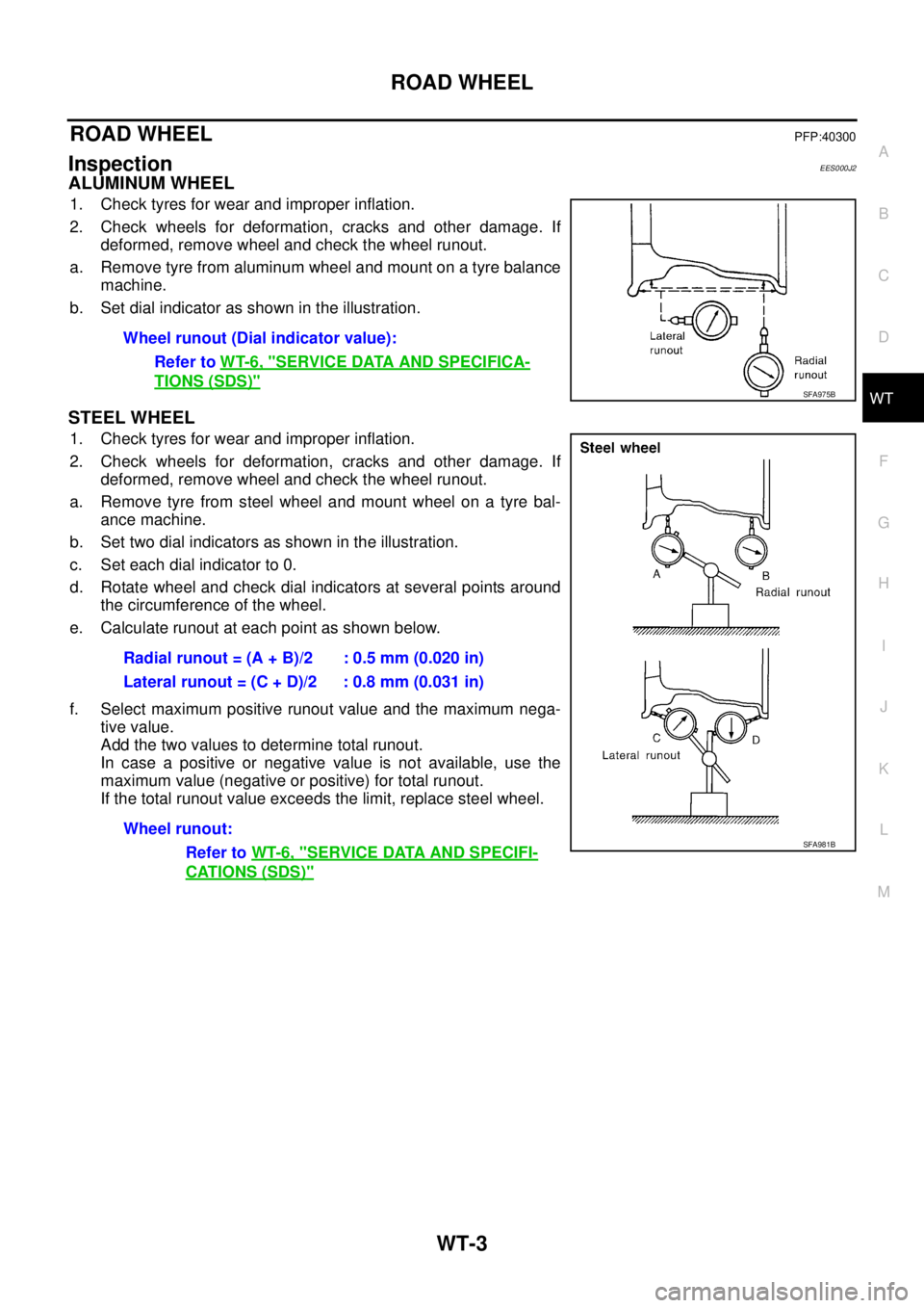
b. Set dial indicator as shown in the illustration.
STEEL WHEEL
1. Check tyres for wear and improper inflation.
2. Check wheels for deformation, cracks and other damage. If
deformed, remove wheel and check the wheel runout.
a. Remove tyre from steel wheel and mount wheel on a tyre bal-
ance machine.
b. Set two dial indicators as shown in the illustration.
c. Set each dial indicator to 0.
d. Rotate wheel and check dial indicators at several points around
the circumference of the wheel.
e. Calculate runout at each point as shown below.
f. Select maximum positive runout value and the maximum nega-
tive value.
Add the two values to determine total runout.
In case a positive or negative value is not available, use the
maximum value (negative or positive) for total runout.
If the total runout value exceeds the limit, replace steel wheel.Wheel runout (Dial indicator value):
Refer to WT-6, "
SERVICE DATA AND SPECIFICA-
TIONS (SDS)"SFA975B
Radial runout = (A + B)/2 : 0.5 mm (0.020 in)
Lateral runout = (C + D)/2 : 0.8 mm (0.031 in)
Wheel runout:
Refer to WT-6, "
SERVICE DATA AND SPECIFI-
CATIONS (SDS)"
SFA981B
Page 3033 of 4555

REAR DISC BRAKE
BR-35
C
D
E
G
H
I
J
K
L
MA
B
BR
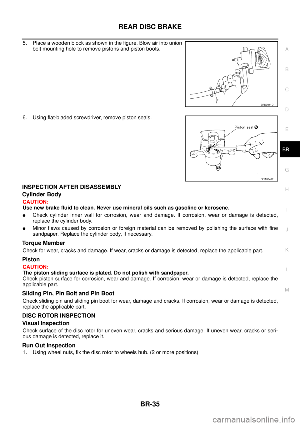
5. Place a wooden block as shown in the figure. Blow air into union
bolt mounting hole to remove pistons and piston boots.
6. Using flat-bladed screwdriver, remove piston seals.
INSPECTION AFTER DISASSEMBLY
Cylinder Body
CAUTION:
Use new brake fluid to clean. Never use mineral oils such as gasoline or kerosene.
�Check cylinder inner wall for corrosion, wear and damage. If corrosion, wear or damage is detected,
replace the cylinder body.
�Minor flaws caused by corrosion or foreign material can be removed by polishing the surface with fine
sandpaper. Replace the cylinder body, if necessary.
To r q u e M e m b e r
Check for wear, cracks and damage. If wear, cracks or damage is detected, replace the applicable part.
Piston
CAUTION:
The piston sliding surface is plated. Do not polish with sandpaper.
Check piston surface for corrosion, wear and damage. If corrosion, wear or damage is detected, replace the
applicable part.
Sliding Pin, Pin Bolt and Pin Boot
Check sliding pin and sliding pin boot for wear, damage and cracks. If corrosion, wear or damage is detected,
replace the applicable part.
DISC ROTOR INSPECTION
Visual Inspection
Check surface of the disc rotor for uneven wear, cracks and serious damage. If uneven wear, cracks or seri-
ous damage is detected, replace it.
Run Out Inspection
1. Using wheel nuts, fix the disc rotor to wheels hub. (2 or more positions)
BRD0041D
SFIA0340E
Page 3447 of 4555

NAVIGATION SYSTEM
AV-105
C
D
E
F
G
H
I
J
L
MA
B
AV
VEHICLE MARK IS IN A RIVER OR SEA
The navigation system moves the vehicle mark with no distinction between land and rivers or sea. If the vehi-
cle mark is somehow out of place, it may appear that the vehicle is driving in a river or the sea.
VEHICLE MARK AUTOMATICALLY ROTATES
The system wrongly memorizes the rotating status as stopping when the ignition switch is turned ON with the
turntable rotating. That causes the vehicle mark to rotate when the vehicle is stopped.
WHEN DRIVING ON SAME ROAD, SOMETIMES VEHICLE MARK IS IN RIGHT PLACE AND
SOMETIMES IT IS WRONG PLACE
The conditions of the GPS antenna (GPS data) and gyroscope (angular speed sensor) change gradually.
Depending on the road traveled and the operation of the steering wheel, the location detection results will be
different. Therefore, even on a road on which the location has never been wrong, conditions may cause the
vehicle mark to deviate.
LOCATION CORRECTION BY MAP-MATCHING IS SLOW
�The map matching function needs to refer to the data of the surrounding area. It is necessary to drive
some distance for the function to work.
�Because map matching operates on this principle, when there are many roads running in similar direc-
tions in the surrounding area, no matching determination may be made. The location may not be cor-
rected until some special feature is found.
ALTHOUGH GPS RECEIVING DISPLAY IS GREEN, VEHICLE MARK DOES NOT RETURN TO
CORRECT LOCATION
�The GPS accuracy has an error of approximately 10 m (30 ft). In some cases the vehicle mark may not be
on the correct street, even when GPS location-correction is done.
�The navigation system compares the results of GPS location detection with the results from map-match-
ing location detection. The one which is determined to have higher accuracy is used.
�GPS location correction may not be performed when the vehicle is stopped.
NAME OF CURRENT PLACE IS NOT DISPLAYED
The current place name may not be displayed if there are no place names displayed on the map screen.
CONTENTS OF DISPLAY DIFFER FOR BIRDVIEW® AND THE (FLAT) MAP SCREEN
Difference of the BIRDVIEW
® Screen From the Flat Map Screen Are As Follows
�The current place name displays names which are primarily in the direction of vehicle travel.
�The amount of time before the vehicle travel or turn angle is updated on the screen is longer than for the
(flat) map display.
�The conditions for display of place names, roads, and other data are different for nearby areas and for
more distant areas.
�Some thinning of the character data is done to prevent the display becoming to complex. In some cases
and in some locations, the display contents may differ.
�The same place name, street name, etc. may be displayed multiple times.