Page 39 of 4555
LIFTING POINT
GI-37
C
D
E
F
G
H
I
J
K
L
MB
GI
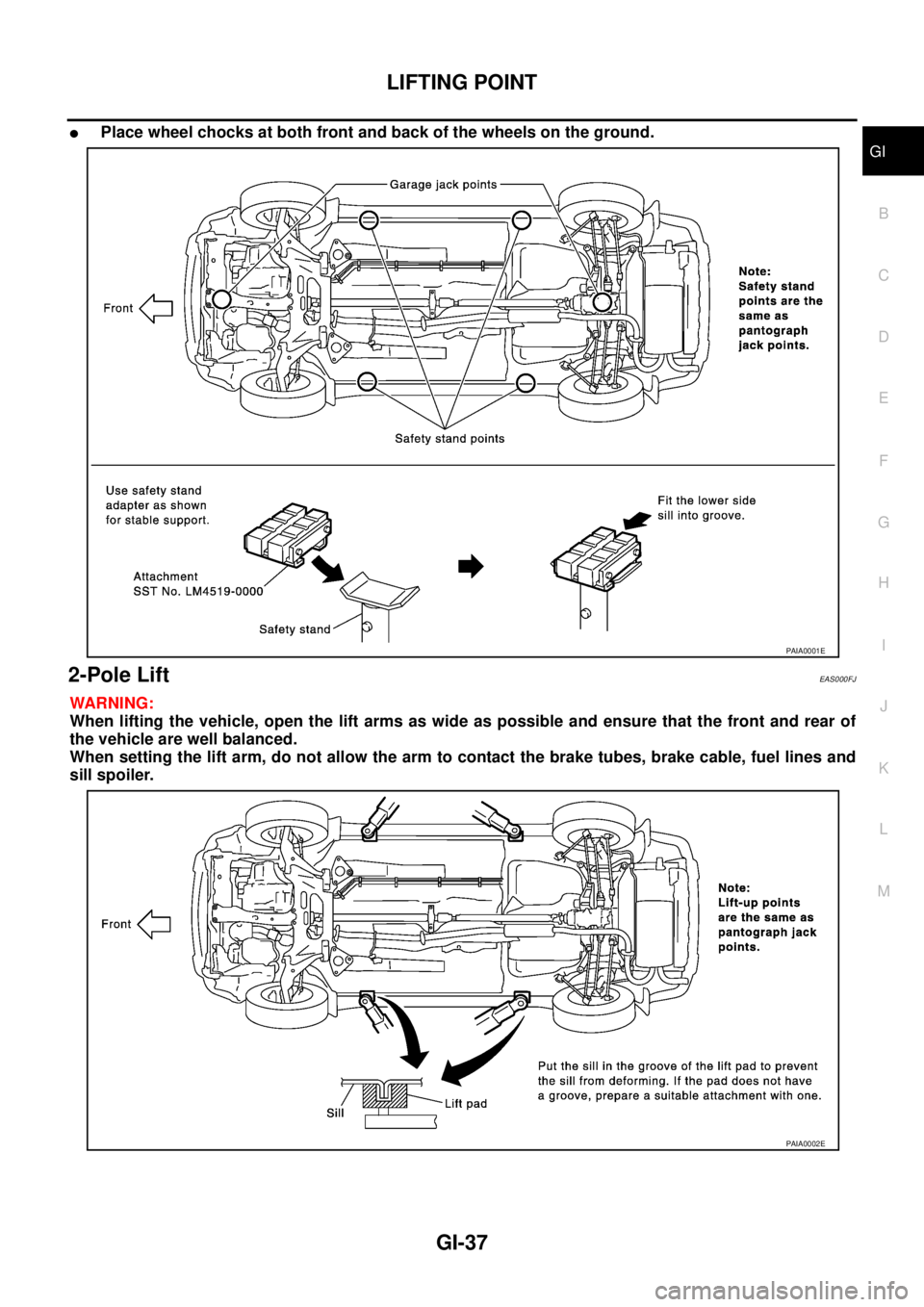
�Place wheel chocks at both front and back of the wheels on the ground.
2-Pole Lift EAS000FJ
WARNING:
When lifting the vehicle, open the lift arms as wide as possible and ensure that the front and rear of
the vehicle are well balanced.
When setting the lift arm, do not allow the arm to contact the brake tubes, brake cable, fuel lines and
sill spoiler.
PAIA0001E
PAIA0002E
Page 41 of 4555
 laws and local laws regarding the towing")
TOW TRUCK TOWING
GI-39
C
D
E
F
G
H
I
J
K
L
MB
GI
TOW TRUCK TOWINGPFP:00000
Tow Truck TowingEAS001JB
CAUTION:
�All applicable state or Provincial (in Canada) laws and local laws regarding the towing operation
must be obeyed.
�It is necessary to use proper towing equipment to avoid possible damage to the vehicle during
towing operation. Towing is in accordance with Towing Procedure Manual at dealer.
�Always attach safety chains before towing.
�When towing, make sure that the transmission, steering system and power train are in good order.
If any unit is damaged, dollies must be used.
�Never tow an automatic transmission model from the rear (that is backward) with four wheels on
the ground. This may cause serious and expensive damage to the transmission.
2WD MODELS
NISSAN recommends that vehicle be towed with the driving (front) wheels off the ground or that a dolly be
used as illustrated.
CAUTION:
�Never tow automatic transmission models with the front wheels on the ground or four wheels on
the ground (forward or backward) as this may cause serious and expensive damage to the trans-
mission.
If it is necessary to tow the vehicle with the rear wheels raised, always use towing dollies under
the front wheels.
�When towing automatic transmission models with the front wheels on towing dollies:
–Turn the ignition key to the OFF position, and secure the steering wheel in a straight ahead posi-
tion with a rope or similar device.
Never secure the steering wheel by turning the ignition key to the LOCK position. This may dam-
age the steering lock mechanism.
–Move the selector lever to the N (Neutral) position.
PAIA0276E
Page 42 of 4555
: Always release the parking brake.
4WD MODELS")
GI-40
TOW TRUCK TOWING
�When towing two wheel drive automatic transmission model with the rear wheels on the ground (if
you do not use towing dollies): Always release the parking brake.
4WD MODELS
NISSAN recommends that a dolly be used as illustrated when towing 4WD models.
CAUTION:
Never tow automatic transmission 4WD models with any of the wheels on the ground as this may
cause serious and expensive damage to the drive train.
Vehicle Recovery (Freeing a Stuck Vehicle) EAS001JC
�Use the recovery hooks only, not other parts of the vehicle. Oth-
erwise, the vehicle body will be damaged.
�Use the recovery hook only to free a vehicle stuck in sand,
snow, mud, etc. Never tow the vehicle for a long distance using
only the recovery hook.
�The recovery hook is under tremendous force when used to free
a stuck vehicle. Always pull the cable straight out from the front
or rear of the vehicle. Never pull on the hook at an angle.
�Stand clear of a stuck vehicle.
WARNING:
�Do not spin the tires at high speed. This could cause them
to explode and result in serious injury. Parts of the vehicle
could also overheat and be damaged.
PAIA0275E
PAIA0014E
Page 53 of 4555
TERMINOLOGY
GI-51
C
D
E
F
G
H
I
J
K
L
MB
GI
***: Not applicableTransmission control module TCM A/T control unit
Turbocharger TC Turbocharger
Vehicle speed sensor VSS Vehicle speed sensor
Volume air flow sensor VAFS Air flow meter
Warm up oxidation catalyst WU-OC Catalyst
Warm up oxidation catalytic converter sys-
temWU-OC system ***
Warm up three way catalyst WU-TWC Catalyst
Warm up three way catalytic converter sys-
temWU-TWC system ***
Wide open throttle position switch WOTP switch Full switchNEW TERMNEW ACRONYM /
ABBREVIATIONOLD TERM
Page 109 of 4555
![NISSAN X-TRAIL 2005 Service Repair Manual TIMING CHAIN
EM-55
[QR]
C
D
E
F
G
H
I
J
K
L
MA
EM
INSPECTION AFTER INSTALLATION
Inspection for Leaks
The following are procedures for checking fluids leak, lubricates leak and exhaust gases leak.
�B](/manual-img/5/57403/w960_57403-108.png "NISSAN X-TRAIL 2005 Service Repair Manual TIMING CHAIN
EM-55
[QR]
C
D
E
F
G
H
I
J
K
L
MA
EM
INSPECTION AFTER INSTALLATION
Inspection for Leaks
The following are procedures for checking fluids leak, lubricates leak and exhaust gases leak.
�B")
TIMING CHAIN
EM-55
[QR]
C
D
E
F
G
H
I
J
K
L
MA
EM
INSPECTION AFTER INSTALLATION
Inspection for Leaks
The following are procedures for checking fluids leak, lubricates leak and exhaust gases leak.
�Before starting engine, check oil/fluid levels including engine coolant and engine oil. If less than required
quantity, fill to the specified level. Refer to MA-17, "
RECOMMENDED FLUIDS AND LUBRICANTS" .
�Use procedure below to check for fuel leakage.
–Turn ignition switch “ON” (with engine stopped). With fuel pressure applied to fuel piping, check for fuel
leakage at connection points.
–Start engine. With engine speed increased, check again for fuel leakage at connection points.
�Run engine to check for unusual noise and vibration.
NOTE:
If hydraulic pressure inside timing chain tensioner drops after removal/installation, slack in the guide may
generate a pounding noise during and just after engine start. However, this is normal. Noise will stop after
hydraulic pressure rises.
�Warm up engine thoroughly to make sure there is no leakage of fuel, exhaust gases, or any oil/fluids
including engine oil and engine coolant.
�Bleed air from lines and hoses of applicable lines, such as in cooling system.
�After cooling down engine, again check oil/fluid levels including engine oil and engine coolant. Refill to the
specified level, if necessary.
Summary of the inspection items:
* Transmission/transaxle/CVT fluid, power steering fluid, brake fluid, etc.Item Before starting engine Engine running After engine stopped
Engine coolant Level Leakage Level
Engine oil Level Leakage Level
Other oils and fluid* Level Leakage Level
Fuel Leakage Leakage Leakage
Exhaust gases — Leakage —
Page 111 of 4555
![NISSAN X-TRAIL 2005 Service Repair Manual CAMSHAFT
EM-57
[QR]
C
D
E
F
G
H
I
J
K
L
MA
EM
CAUTION:
To avoid power steering fluid leakage, temporarily fix power steering reservoir tank vertically.
4. Remove intake valve timing control cover wi](/manual-img/5/57403/w960_57403-110.png "NISSAN X-TRAIL 2005 Service Repair Manual CAMSHAFT
EM-57
[QR]
C
D
E
F
G
H
I
J
K
L
MA
EM
CAUTION:
To avoid power steering fluid leakage, temporarily fix power steering reservoir tank vertically.
4. Remove intake valve timing control cover wi")
CAMSHAFT
EM-57
[QR]
C
D
E
F
G
H
I
J
K
L
MA
EM
CAUTION:
To avoid power steering fluid leakage, temporarily fix power steering reservoir tank vertically.
4. Remove intake valve timing control cover with the following procedure:
a. Disconnect intake valve timing control solenoid valve harness connector.
b. Remove intake valve timing control solenoid valve, if necessary.
c. Disconnect ground cables.
d. Loosen bolts in reverse order as shown in the figure.
e . U s e a s e a l c u t t e r ( s p e c i a l s e r v i c e t o o l : K V 1 0 1111 0 0 ) o r e q u i v a -
lent tool to cut liquid gasket for removal.
5. Pull chain guide between camshaft sprockets out through front cover.
6. Set No. 1 cylinder at TDC on its compression stroke with the following procedure:
a. Open splash guard on RH undercover.
b. Rotate crankshaft pulley clockwise and align TDC mark to timing
indicator on front cover.
c. At the same time, make sure that the mating marks on camshaft
sprockets are located as shown in the figure.
�If not, rotate crankshaft pulley one more turn to align mating
marks to the positions in the figure.
7. Remove camshaft sprockets with the following procedure:
a. Line up the mating marks on camshaft sprockets, and paint indelible mating marks on timing chain link
plate.
KBIA0085E
KBIA0190E
PBIC2351E
Page 127 of 4555
![NISSAN X-TRAIL 2005 Service Repair Manual CYLINDER HEAD
EM-73
[QR]
C
D
E
F
G
H
I
J
K
L
MA
EM
INSTALLATION
1. Install cylinder head gasket.
2. Tighten cylinder head bolts in numerical order as shown in figure
with the following procedure, an](/manual-img/5/57403/w960_57403-126.png "NISSAN X-TRAIL 2005 Service Repair Manual CYLINDER HEAD
EM-73
[QR]
C
D
E
F
G
H
I
J
K
L
MA
EM
INSTALLATION
1. Install cylinder head gasket.
2. Tighten cylinder head bolts in numerical order as shown in figure
with the following procedure, an")
CYLINDER HEAD
EM-73
[QR]
C
D
E
F
G
H
I
J
K
L
MA
EM
INSTALLATION
1. Install cylinder head gasket.
2. Tighten cylinder head bolts in numerical order as shown in figure
with the following procedure, and install cylinder head.
CAUTION:
If cylinder head bolts are re-used, check their outer diame-
ters before installation. Refer to EM-72, "
Cylinder Head
Bolts Outer Diameter" .
a. Apply new engine oil to threads and seating surface of mounting
bolts.
b. Tighten all bolts.
c. Turn all bolts 60 degrees clockwise (angle tightening).
d. Completely loosen.
CAUTION:
In this step, loosen bolts in reverse order of that indicated in the figure.
e. Tighten all bolts.
f. Turn all bolts 75 degrees clockwise (angle tightening).
g. Turn all bolts 75 degrees clockwise again (angle tightening).
CAUTION:
Check and confirm the tightening angle by using an angle
wrench (special service tool) or protractor. Avoid judgment
by visual inspection without the tool.
3. Install in the reverse order of removal after this step.
INSPECTION AFTER INSTALLATION
Inspection for Leaks
The following are procedures for checking fluids leak, lubricates leak and exhaust gases leak.
�Before starting engine, check oil/fluid levels including engine coolant and engine oil. If less than required
quantity, fill to the specified level. Refer to MA-17, "
RECOMMENDED FLUIDS AND LUBRICANTS" .
�Use procedure below to check for fuel leakage.
–Turn ignition switch “ON” (with engine stopped). With fuel pressure applied to fuel piping, check for fuel
leakage at connection points.
–Start engine. With engine speed increased, check again for fuel leakage at connection points.
�Run engine to check for unusual noise and vibration.
�Warm up engine thoroughly to make sure there is no leakage of fuel, exhaust gases, or any oil/fluids
including engine oil and engine coolant.
�Bleed air from lines and hoses of applicable lines, such as in cooling system.
�After cooling down engine, again check oil/fluid levels including engine oil and engine coolant. Refill to the
specified level, if necessary. : 50 N·m (5.1 kg-m, 37 ft-lb)
: 0 N·m (0 kg-m, 0 ft-lb)
: 39.2 N·m (4.0 kg-m, 29 ft-lb)
KBIA0058E
KBIA0059E
Page 135 of 4555
![NISSAN X-TRAIL 2005 Service Repair Manual ENGINE ASSEMBLY
EM-81
[QR]
C
D
E
F
G
H
I
J
K
L
MA
EM
ENGINE ASSEMBLYPFP:10001
Removal and Installation (2WD Models)EBS01FKJ
WARNING:
�Situate the vehicle on a flat and solid surface.
�Place chocks a](/manual-img/5/57403/w960_57403-134.png "NISSAN X-TRAIL 2005 Service Repair Manual ENGINE ASSEMBLY
EM-81
[QR]
C
D
E
F
G
H
I
J
K
L
MA
EM
ENGINE ASSEMBLYPFP:10001
Removal and Installation (2WD Models)EBS01FKJ
WARNING:
�Situate the vehicle on a flat and solid surface.
�Place chocks a")
ENGINE ASSEMBLY
EM-81
[QR]
C
D
E
F
G
H
I
J
K
L
MA
EM
ENGINE ASSEMBLYPFP:10001
Removal and Installation (2WD Models)EBS01FKJ
WARNING:
�Situate the vehicle on a flat and solid surface.
�Place chocks at front and back of rear wheels.
�For engines not equipped with engine slingers, attach proper slingers and bolts described in
PARTS CATALOG.
CAUTION:
�Always be careful to work safely, avoid forceful or uninstructed operations.
�Do not start working until exhaust system and coolant are cool enough.
�If items or work required are not covered by the engine section, refer to the applicable sections.
�Always use the support point specified for lifting.
�Use either 2-pole lift type or separate type lift as best you can. If board-on type is used for
unavoidable reasons, support at the rear axle jacking point with a transmission jack or similar tool
before starting work, in preparation for the backward shift of center of gravity.
�For supporting points for lifting and jacking point at rear axle, refer to GI-36, "Garage Jack and
Safety Stand" .
1. Rear engine mounting insulator 2. Rubber seat 3. Rear engine mounting bracket
4. RH engine mounting insulator 5. RH engine mounting bracket 6. Front engine mounting bracket
7. Front engine mounting insulator 8. Grommet 9. Center member
10. LH engine mounting insulator 11. Stopper 12. LH engine mounting bracket
PBIC3831E