Page 361 of 4555
![NISSAN X-TRAIL 2005 Service Repair Manual OVERHEATING CAUSE ANALYSIS
CO-5
[QR]
C
D
E
F
G
H
I
J
K
L
MA
CO
OVERHEATING CAUSE ANALYSISPFP:00012
Troubleshooting ChartEBS00KOD
Symptom Check items
Cooling sys-
tem parts
malfunctionPoor heat tran](/manual-img/5/57403/w960_57403-360.png "NISSAN X-TRAIL 2005 Service Repair Manual OVERHEATING CAUSE ANALYSIS
CO-5
[QR]
C
D
E
F
G
H
I
J
K
L
MA
CO
OVERHEATING CAUSE ANALYSISPFP:00012
Troubleshooting ChartEBS00KOD
Symptom Check items
Cooling sys-
tem parts
malfunctionPoor heat tran")
OVERHEATING CAUSE ANALYSIS
CO-5
[QR]
C
D
E
F
G
H
I
J
K
L
MA
CO
OVERHEATING CAUSE ANALYSISPFP:00012
Troubleshooting ChartEBS00KOD
Symptom Check items
Cooling sys-
tem parts
malfunctionPoor heat transferWater pump malfunction Worn or loose drive belt
— Thermostat and water con-
trol valve stuck closed—
Damaged finsDust contamination or
paper clogging
Physical damage
Clogged radiator cooling
tubeExcess foreign material
(rust, dirt, sand, etc.)
Reduced air flowCooling fan does not oper-
ate
Fan assembly — High resistance to fan rota-
tion
Damaged fan blades
Damaged radiator shroud — — —
Improper engine coolant
mixture ratio—— —
Poor engine coolant quality — Engine coolant viscosity —
Insufficient engine coolantEngine coolant leaksCooling hoseLoose clamp
Cracked hose
Water pump Poor sealing
Radiator capLoose
Poor sealing
RadiatorO-ring for damage, deterio-
ration or improper fitting
Cracked radiator tank
Cracked radiator core
Reservoir tank Cracked reservoir tank
Overflowing reservoir tankExhaust gas leaks into
cooling systemCylinder head deterioration
Cylinder head gasket dete-
rioration
Page 362 of 4555
CO-6
[QR]
OVERHEATING CAUSE ANALYSIS
Except cool-
ing system
parts mal-
function— Overload on engineAbusive drivingHigh engine rpm under no
load
Driving in low gear for
extended time
Driving at extremely high
speed
Power train system mal-
function
— Installed improper size
wheels and tires
Dragging brakes
Improper ignition timing
Blocked or restricted air
flowBlocked bumper —
— Blocked radiator grilleInstalled car brassiere
Mud contamination or
paper clogging
Blocked radiator —
Blocked condenser
Blocked air flow
Installed large fog lamp Symptom Check items
Page 365 of 4555
![NISSAN X-TRAIL 2005 Service Repair Manual ENGINE COOLANT
CO-9
[QR]
C
D
E
F
G
H
I
J
K
L
MA
CO
ENGINE COOLANTPFP:KQ100
InspectionEBS00KOG
LEVEL CHECK
�Check if the reservoir tank engine coolant level is within “MIN” to
“MAX” range whe](/manual-img/5/57403/w960_57403-364.png "NISSAN X-TRAIL 2005 Service Repair Manual ENGINE COOLANT
CO-9
[QR]
C
D
E
F
G
H
I
J
K
L
MA
CO
ENGINE COOLANTPFP:KQ100
InspectionEBS00KOG
LEVEL CHECK
�Check if the reservoir tank engine coolant level is within “MIN” to
“MAX” range whe")
ENGINE COOLANT
CO-9
[QR]
C
D
E
F
G
H
I
J
K
L
MA
CO
ENGINE COOLANTPFP:KQ100
InspectionEBS00KOG
LEVEL CHECK
�Check if the reservoir tank engine coolant level is within “MIN” to
“MAX” range when engine is cool.
�Adjust engine coolant level as necessary.
LEAK CHECK
�To check for leakage, apply pressure to the cooling system with
a radiator cap tester (commercial service tool) and a radiator
cap tester adapter (special service tool).
WARNING:
Do not remove radiator cap when engine is hot. Serious
burns could occur from high-pressure engine coolant
escaping from radiator.
CAUTION:
Higher test pressure than specified may cause radiator
damage.
NOTE:
In a case that engine coolant decreases, replenish radiator with engine coolant.
�If anything is found, repair or replace damaged parts.
Changing Engine CoolantEBS00KOH
WARNING:
�To avoid being scalded, do not change engine coolant when engine is hot.
�Wrap a thick cloth around radiator cap and carefully remove the cap. First, turn the cap a quarter
of a turn to release built-up pressure. Then turn the cap all the way.
�Be careful not to allow engine coolant to contact drive belt.
DRAINING ENGINE COOLANT
1. Remove RH and LH undercovers.
2. Open radiator drain plug at the bottom of radiator, and then
remove radiator cap.
When drain all of engine coolant in the system, open water drain plug on cylinder block. Refer to
EM-94, "
ASSEMBLY" .
3. Remove reservoir tank as necessary, and drain engine coolant and clean reservoir tank before installing.
SMA412B
Testing pressure:
157 kPa (1.57 bar, 1.6 kg/cm
2 , 23 psi)
SLC134B
PBIC2250E
Page 366 of 4555
![NISSAN X-TRAIL 2005 Service Repair Manual CO-10
[QR]
ENGINE COOLANT
4. Check drained engine coolant for contaminants such as rust, corrosion or discoloration. If contaminated,
flush the engine cooling system. Refer to CO-10, "
FLUSHING COOL](/manual-img/5/57403/w960_57403-365.png "NISSAN X-TRAIL 2005 Service Repair Manual CO-10
[QR]
ENGINE COOLANT
4. Check drained engine coolant for contaminants such as rust, corrosion or discoloration. If contaminated,
flush the engine cooling system. Refer to CO-10, \"
FLUSHING COOL")
CO-10
[QR]
ENGINE COOLANT
4. Check drained engine coolant for contaminants such as rust, corrosion or discoloration. If contaminated,
flush the engine cooling system. Refer to CO-10, "
FLUSHING COOLING SYSTEM" .
REFILLING ENGINE COOLANT
1. Install reservoir tank if removed, and radiator drain plug.
CAUTION:
Be sure to clean drain plug and install with new O-ring.
�If water drain plug on cylinder block is removed, close and tighten it. Refer to EM-89, "CYLIN-
DER BLOCK" .
2. Make sure that each hose clamp has been firmly tightened.
3. Fill radiator and reservoir tank to specified level.
�Pour engine coolant through engine coolant filler neck
slowly of less than 2 (1-3/4 lmp qt) a minute to allow air
in system to escape.
�Use Genuine NISSAN Anti-freeze Coolant or equivalent
mixed with water (distilled or demineralized). Refer to
MA-17, "
RECOMMENDED FLUIDS AND LUBRICANTS".
4. Install radiator cap.
5. Warm up until opening thermostat and water control valve. Standard for warming-up time is approximately
10 minutes at 3,000 rpm.
�Make sure thermostat opening condition by touching radiator hose (lower) to see a flow of warm water.
CAUTION:
Watch water temperature gauge so as not to overheat the engine.
6. Stop the engine and cool down to less than approximately 50°C (122°F).
�Cool down using fan to reduce the time.
�If necessary, refill radiator up to filler neck with engine coolant.
7. Refill reservoir tank to “MAX” level line with engine coolant.
8. Repeat steps 3 through 6 two or more times with radiator cap installed until the engine coolant level no
longer drops.
9. Check cooling system for leaks with the engine running.
10. Warm up the engine, and check for sound of engine coolant flow while running the engine from idle up to
3,000 rpm with heater temperature controller set at several position between “COOL” and “WARM”.
�Sound may be noticeable at heater unit.
11. Repeat step 10 three times.
12. If sound is heard, bleed air from cooling system by repeating step 3 through 6 until the engine coolant
level no longer drops.
FLUSHING COOLING SYSTEM
1. Install reservoir tank if removed, and radiator drain plug.Engine coolant capacity
(with reservoir tank at “MAX” level)
: Approx. 7.1 (6-1/4 lmp qt)
SMA182B
Reservoir tank capacity (at “MAX” level)
: 0.7 (5/8 lmp qt)
SMA412B
Page 369 of 4555
![NISSAN X-TRAIL 2005 Service Repair Manual RADIATOR
CO-13
[QR]
C
D
E
F
G
H
I
J
K
L
MA
CO
INSTALLATION
Installation is the reverse order of removal.
INSPECTION AFTER INSTALLATION
�Check for leaks of engine coolant using a radiator cap tester](/manual-img/5/57403/w960_57403-368.png "NISSAN X-TRAIL 2005 Service Repair Manual RADIATOR
CO-13
[QR]
C
D
E
F
G
H
I
J
K
L
MA
CO
INSTALLATION
Installation is the reverse order of removal.
INSPECTION AFTER INSTALLATION
�Check for leaks of engine coolant using a radiator cap tester")
RADIATOR
CO-13
[QR]
C
D
E
F
G
H
I
J
K
L
MA
CO
INSTALLATION
Installation is the reverse order of removal.
INSPECTION AFTER INSTALLATION
�Check for leaks of engine coolant using a radiator cap tester adapter (special service tool: EG17650301)
and a radiator cap tester (commercial service tool). Refer to CO-9, "
LEAK CHECK" .
�Start and warm up engine. Visually check if there is no leaks of engine coolant and A/T fluid (A/T models).
Checking Radiator CapEBS00KOK
�Check valve seat of radiator cap.
–Check if valve seat is swollen to the extent that the edge of the
plunger cannot be seen when watching it vertically from the top.
–Check if valve seat has no soil and damage.
�Pull negative-pressure valve to open it, and make sure that it is
completely closed when released.
–Make sure that there is no dirt or damage on the valve seat of
radiator cap negative-pressure valve.
–Make sure that there are no unusualness in the opening and
closing conditions of negative-pressure valve.
�Check radiator cap relief pressure.
–When connecting radiator cap to the radiator cap tester (com-
mercial service tool) and the radiator cap tester adapter [SST],
apply engine coolant to the cap seal surface.
�Replace radiator cap if there is an unusualness related to the above three.
CAUTION:
When installing radiator cap, thoroughly wipe out the radiator filler neck to remove any waxy residue
or foreign material.
Checking RadiatorEBS00KOL
Check radiator for mud or clogging. If necessary, clean radiator as follows.
�Be careful not to bend or damage radiator fins.
�When radiator is cleaned without removal, remove all surrounding parts such as cooling fan, radiator
shroud and horns. Then tape harness and connectors to prevent water from entering.
1. Apply water by hose to the back side of the radiator core vertically downward.
2. Apply water again to all radiator core surface once per minute.
PBIC2816E
SMA967B
Standard:
78 - 98 kPa (0.78 - 0.98bar, 0.8 - 1.0 kg/cm
2 , 11 - 14 psi)
Limit:
59 kPa (0.59bar, 0.6 kg/cm
2 , 9 psi)
SLC755AC
Page 374 of 4555
CO-18
[QR]
RADIATOR (ALUMINUM TYPE)
4. Make sure that the rim is completely crimped down.
5. Make sure that there is no leakage.
Refer to CO-18, "
INSPECTION" .
INSPECTION
1. Apply pressure with radiator cap tester adapter (special service
tool) and radiator cap tester (commercial service tool).
WARNING:
To prevent the risk of hose coming undone while under
pressure, securely fasten it down with hose clamp.
CAUTION:
Attach hose to A/T fluid cooler to seal its inlet and outlet.
(A/T models)
2. Check for leakage by soaking radiator in water container with
the testing pressure applied.Standard height “H” : 8.0 - 8.4 mm (0.315 - 0.331 in)
SLC554A
Testing pressure
: 157 kPa (1.57 bar, 1.6 kg/cm
2 , 23 psi)
SLC933
SLC934
Page 378 of 4555
CO-22
[QR]
WATER PUMP
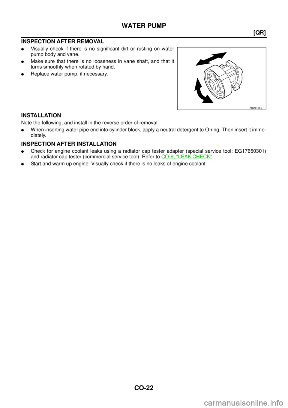
INSPECTION AFTER REMOVAL
�Visually check if there is no significant dirt or rusting on water
pump body and vane.
�Make sure that there is no looseness in vane shaft, and that it
turns smoothly when rotated by hand.
�Replace water pump, if necessary.
INSTALLATION
Note the following, and install in the reverse order of removal.
�When inserting water pipe end into cylinder block, apply a neutral detergent to O-ring. Then insert it imme-
diately.
INSPECTION AFTER INSTALLATION
�Check for engine coolant leaks using a radiator cap tester adapter (special service tool: EG17650301)
and radiator cap tester (commercial service tool). Refer to CO-9, "
LEAK CHECK" .
�Start and warm up engine. Visually check if there is no leaks of engine coolant.
KBIA0155E
Page 380 of 4555
![NISSAN X-TRAIL 2005 Service Repair Manual CO-24
[QR]
THERMOSTAT AND WATER CONTROL VALVE
INSPECTION AFTER REMOVAL
�Place a thread so that it is caught in the valves of thermostat and
water control valve. Immerse fully in a container filled w](/manual-img/5/57403/w960_57403-379.png "NISSAN X-TRAIL 2005 Service Repair Manual CO-24
[QR]
THERMOSTAT AND WATER CONTROL VALVE
INSPECTION AFTER REMOVAL
�Place a thread so that it is caught in the valves of thermostat and
water control valve. Immerse fully in a container filled w")
CO-24
[QR]
THERMOSTAT AND WATER CONTROL VALVE
INSPECTION AFTER REMOVAL
�Place a thread so that it is caught in the valves of thermostat and
water control valve. Immerse fully in a container filled with water.
Heat while stirring. (The example in the figure shows thermo-
stat.)
�The valve opening temperature is the temperature at which the
valve opens and falls from the thread.
�Continue heating. Check the maximum valve lift amount.
NOTE:
The maximum valve lift amount standard temperature for water
control valve is the reference value.
�After checking the maximum valve lift amount, lower the water
temperature and check the valve closing temperature.
Standard:
�If out of the standard, replace either or both thermostat and water control valve.
INSTALLATION
Note the following, and install in the reverse order of removal.
Thermostat and Water Control Valve
�Install thermostat with making rubber ring groove fit to thermo-
stat flange with the whole circumference. (The example in the
figure shows thermostat.)
NOTE:
Same procedure is applied for installation of water control valve.
�Install thermostat with jiggle valve facing upwards. (The position
deviation may be within the range of 20 degrees as shown in the
figure.)
�Install water control valve with the arrow facing up and the frame
center part facing upwards. (The position deviation may be
within the range of 20 degrees as shown in the figure.)
Heater Pipe Installation
Apply a neutral detergent to O-ring, then quickly insert the insertion part of heater pipe into cylinder block.
INSPECTION AFTER INSTALLATION
�Check for leaks of engine coolant using a radiator cap tester adapter (special service tool: EG17650301)
and a radiator cap tester (commercial service tool). Refer to CO-9, "
LEAK CHECK" .
�Start and warm up engine. Visually check if there is no leaks of engine coolant and A/T fluid (A/T models).
SLC252B
Items Thermostat Water control valve
Valve opening temperature 80.5 - 83.5°C (177 - 182°F) 93.5 - 96.5°C (200 - 206°F)
Maximum valve lift 8 mm/ 95°C (0.315 in/ 203°F) 8 mm/ 108°C (0.315 in/ 226°F)
Valve closing temperature 77°C (171°F) 90°C (194°F)
PBIC0157E
PBIC0158E
![NISSAN X-TRAIL 2005 Service Repair Manual CO-6
[QR]
OVERHEATING CAUSE ANALYSIS
Except cool-
ing system
parts mal-
function— Overload on engineAbusive drivingHigh engine rpm under no
load
Driving in low gear for
extended time
Driving at](/manual-img/5/57403/w960_57403-361.png "NISSAN X-TRAIL 2005 Service Repair Manual CO-6
[QR]
OVERHEATING CAUSE ANALYSIS
Except cool-
ing system
parts mal-
function— Overload on engineAbusive drivingHigh engine rpm under no
load
Driving in low gear for
extended time
Driving at")
![NISSAN X-TRAIL 2005 Service Repair Manual CO-18
[QR]
RADIATOR (ALUMINUM TYPE)
4. Make sure that the rim is completely crimped down.
5. Make sure that there is no leakage.
Refer to CO-18, "
INSPECTION" .
INSPECTION
1. Apply pressure with rad](/manual-img/5/57403/w960_57403-373.png "NISSAN X-TRAIL 2005 Service Repair Manual CO-18
[QR]
RADIATOR (ALUMINUM TYPE)
4. Make sure that the rim is completely crimped down.
5. Make sure that there is no leakage.
Refer to CO-18, \"
INSPECTION\" .
INSPECTION
1. Apply pressure with rad")