2005 NISSAN NAVARA maintenance
[x] Cancel search: maintenancePage 1625 of 3171
PRECAUTIONS
GI-3
C
D
E
F
G
H
I
J
K
L
MB
GI
PRECAUTIONSPFP:00001
DescriptionEAS001GG
Observe the following precautions to ensure safe and proper servicing. These precautions are not
described in each individual section.
Precautions for Supplemental Restraint System (SRS) “AIR BAG” and “SEAT
BELT PRE-TENSIONER”
EAS001GH
The Supplemental Restraint System such as “AIR BAG” and “SEAT BELT PRE-TENSIONER”, used along
with a front seat belt, helps to reduce the risk or severity of injury to the driver and front passenger for certain
types of collision. Information necessary to service the system safely is included in the SRS and SB section of
this Service Manual.
WARNING:
lTo avoid rendering the SRS inoperative, which could increase the risk of personal injury or death
in the event of a collision which would result in air bag inflation, all maintenance must be per-
formed by an authorized NISSAN/INFINITI dealer.
lImproper maintenance, including incorrect removal and installation of the SRS, can lead to per-
sonal injury caused by unintentional activation of the system. For removal of Spiral Cable and Air
Bag Module, see the SRS section.
lDo not use electrical test equipment on any circuit related to the SRS unless instructed to in this
Service Manual. SRS wiring harnesses can be identified by yellow and/or orange harnesses or
harness connectors.
Precautions for NATS (NISSAN ANTI-THEFT SYSTEM)EAS001GI
NATS will immobilize the engine if someone tries to start it without the registered key of NATS.
Both of the originally supplied ignition key IDs have been NATS registered.
The security indicator is located on the instrument panel. The indicator blinks when the immobilizer system is
functioning.
Therefore, NATS warns outsiders that the vehicle is equipped with the anti-theft system.
lWhen NATS detects trouble, the security indicator lamp lights up while ignition switch is in "ON" position.
This lighting up indicates that the anti-theft is not functioning, so prompt service is required.
lWhen servicing NATS (trouble diagnoses, system initialization and additional registration of other NATS
ignition key IDs), CONSULT-II hardware and CONSULT-II NATS software is necessary.
Regarding the procedures of NATS initialization and NATS ignition key ID registration, refer to CONSULT-
II operation manual, NATS.
Therefore, CONSULT-II NATS software (program card and operation manual) must be kept strictly con-
fidential to maintain the integrity of the anti-theft function.
lWhen servicing NATS (trouble diagnoses, system initialization and additional registration of other NATS
ignition key IDs), it may be necessary to re-register original key identification. Therefore, be sure to
receive all keys from vehicle owner. A maximum of four or five key IDs can be registered into NATS.
lWhen failing to start the engine first time using the key of NATS, start as follows.
1. Leave the ignition key in "ON" position for approximately 5 seconds.
2. Turn ignition key to "OFF" or "LOCK" position and wait approximately 5 seconds.
3. Repeat step 1 and 2 again.
4. Restart the engine while keeping the key separate from any others on key-chain.
Precautions Necessary for Steering Wheel Rotation After Battery DisconnectEAS001HY
NOTE:
lThis Procedure is applied only to models with Intelligent Key system and NATS (NISSAN ANTI-THEFT
SYSTEM).
lRemove and install all control units after disconnecting both battery cables with the ignition knob in the
²LOCK²position.
lAlways use CONSULT-II to perform self-diagnosis as a part of each function inspection after finishing
work. If DTC is detected, perform trouble diagnosis according to self-diagnostic results.
For models equipped with the Intelligent Key system and NATS, an electrically controlled steering lock mech-
anism is adopted on the key cylinder.
Page 1628 of 3171
GI-6
PRECAUTIONS
CAUTION:
Do not use leaded gasoline. Using leaded gasoline will damage the three way catalyst. Using a fuel
other than that specified could adversely affect the emission control devices and systems, and could
also affect the warranty coverage validity.
DIESEL ENGINE
Diesel fuel of at least 50 cetane.
If two types of diesel fuel are available, use summer or winter fuel properly according to the following temper-
ature conditions.
lAbove –7°C(20°F) ... Summer type diesel fuel.
lBelow –7°C(20°F) ... Winter type diesel fuel.
CAUTION:
lDo not use home heating oil, gasoline or other alternate fuels in your diesel engine. The use of
those can cause engine damage.
lDo not use summer fuel at temperatures below –7°C(20°F). The cold temperatures will cause wax
to form in the fuel. As a result, it may prevent the engine from running smoothly.
lDo not add gasoline or other alternate fuels to diesel fuel.
Precautions for Multiport Fuel Injection System or Engine Control SystemEAS001GN
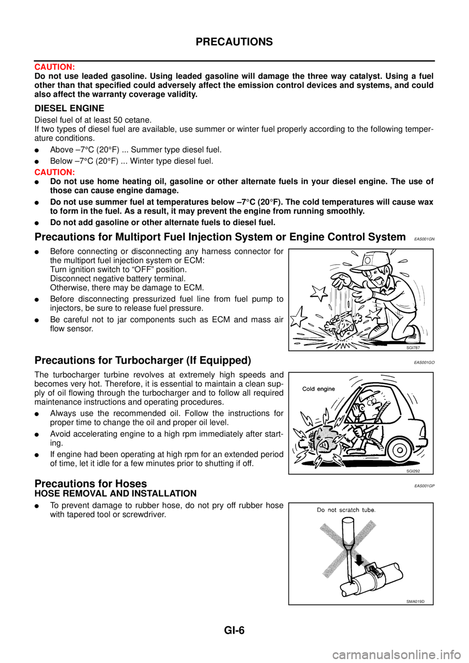
lBefore connecting or disconnecting any harness connector for
the multiport fuel injection system or ECM:
Turn ignition switch to “OFF” position.
Disconnect negative battery terminal.
Otherwise, there may be damage to ECM.
lBefore disconnecting pressurized fuel line from fuel pump to
injectors, be sure to release fuel pressure.
lBe careful not to jar components such as ECM and mass air
flow sensor.
Precautions for Turbocharger (If Equipped)EAS001GO
The turbocharger turbine revolves at extremely high speeds and
becomes very hot. Therefore, it is essential to maintain a clean sup-
ply of oil flowing through the turbocharger and to follow all required
maintenance instructions and operating procedures.
lAlways use the recommended oil. Follow the instructions for
proper time to change the oil and proper oil level.
lAvoid accelerating engine to a high rpm immediately after start-
ing.
lIf engine had been operating at high rpm for an extended period
of time, let it idle for a few minutes prior to shutting if off.
Precautions for HosesEAS001GP
HOSE REMOVAL AND INSTALLATION
lTo prevent damage to rubber hose, do not pry off rubber hose
with tapered tool or screwdriver.
SGI787
SGI292
SMA019D
Page 1689 of 3171
PRECAUTIONS
GW-3
C
D
E
F
G
H
J
K
L
MA
B
GW
PRECAUTIONSPFP:00001
Precautions for Supplemental Restraint System (SRS) “AIR BAG” and “SEAT
BELT PRE-TENSIONER”
EIS00CED
The Supplemental Restraint System such as “AIR BAG” and “SEAT BELT PRE-TENSIONER”, used along
with a front seat belt, helps to reduce the risk or severity of injury to the driver and front passenger for certain
types of collision. Information necessary to service the system safely is included in the SRS and SB section of
this Service Manual.
WARNING:
lTo avoid rendering the SRS inoperative, which could increase the risk of personal injury or death
in the event of a collision which would result in air bag inflation, all maintenance must be per-
formed by an authorized NISSAN/INFINITI dealer.
lImproper maintenance, including incorrect removal and installation of the SRS, can lead to per-
sonal injury caused by unintentional activation of the system. For removal of Spiral Cable and Air
Bag Module, see the SRS section.
lDo not use electrical test equipment on any circuit related to the SRS unless instructed to in this
Service Manual. SRS wiring harnesses can be identified by yellow and/or orange harnesses or
harness connectors.
Precautions for Procedures without Cowl Top CoverEIS00DGM
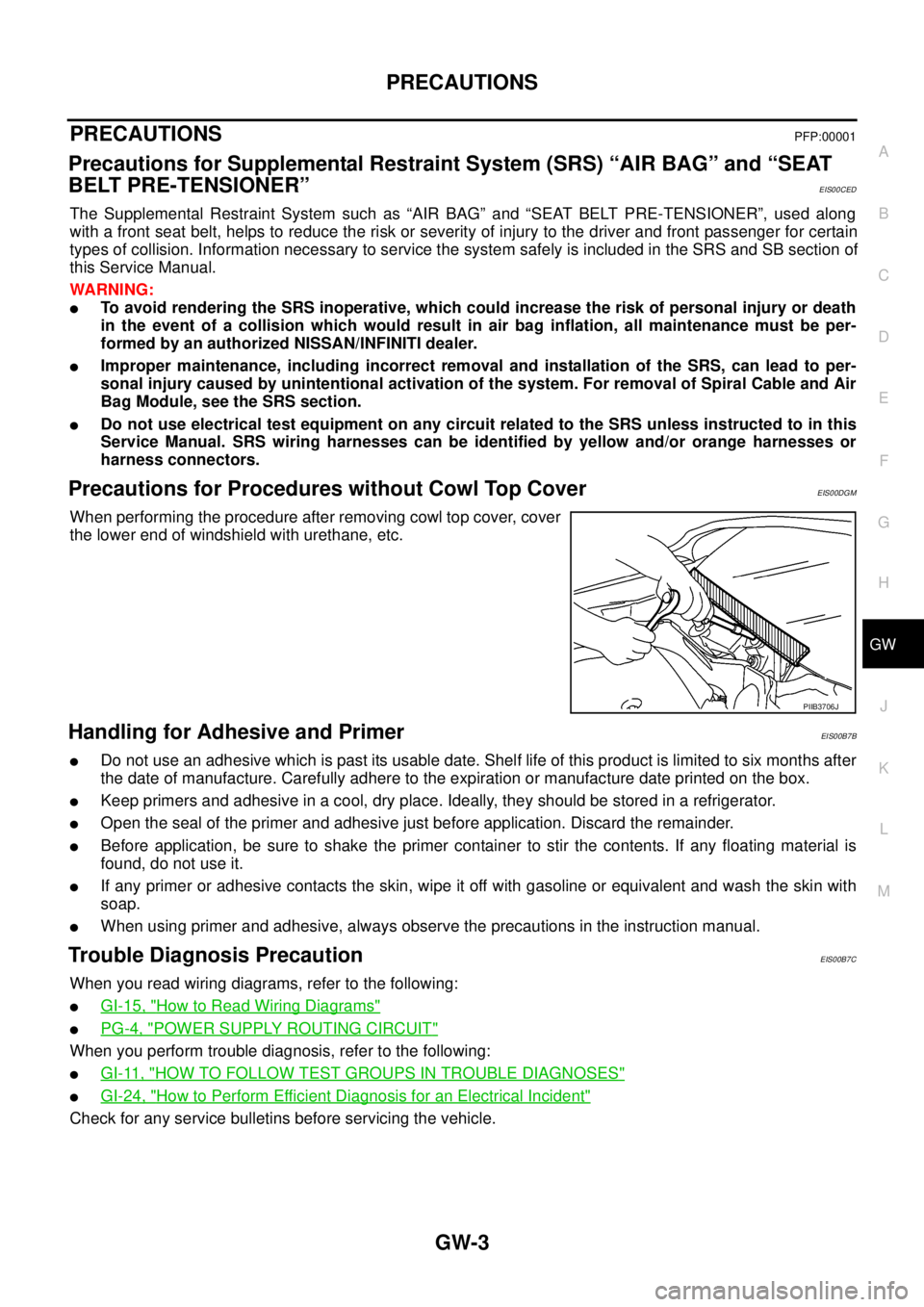
When performing the procedure after removing cowl top cover, cover
the lower end of windshield with urethane, etc.
Handling for Adhesive and PrimerEIS00B7B
lDo not use an adhesive which is past its usable date. Shelf life of this product is limited to six months after
the date of manufacture. Carefully adhere to the expiration or manufacture date printed on the box.
lKeep primers and adhesive in a cool, dry place. Ideally, they should be stored in a refrigerator.
lOpen the seal of the primer and adhesive just before application. Discard the remainder.
lBefore application, be sure to shake the primer container to stir the contents. If any floating material is
found, do not use it.
lIf any primer or adhesive contacts the skin, wipe it off with gasoline or equivalent and wash the skin with
soap.
lWhen using primer and adhesive, always observe the precautions in the instruction manual.
Trouble Diagnosis PrecautionEIS00B7C
When you read wiring diagrams, refer to the following:
lGI-15, "How to Read Wiring Diagrams"
lPG-4, "POWER SUPPLY ROUTING CIRCUIT"
When you perform trouble diagnosis, refer to the following:
lGI-11, "HOW TO FOLLOW TEST GROUPS IN TROUBLE DIAGNOSES"
lGI-24, "How to Perform Efficient Diagnosis for an Electrical Incident"
Check for any service bulletins before servicing the vehicle.
PIIB3706J
Page 1755 of 3171
IDX-3
A
C
D
E
F
G
H
I
J
K
L B
IDX
ALPHABETICAL INDEX
C
Camshaft ...........................................................EM-59
Camshaft inspection ..........................................EM-60
Camshaft position sensor (CMPS) .....EC-82,EC-171,
EC-177
CAN ....................................................................DI-65
CAN - Wiring diagram ...........EC-80,LAN-26,LAN-44,
LAN-56
,LAN-68,LAN-82,LAN-96,LAN-112,LAN-125,
LAN-139
,LAN-152,LAN-166,LAN-181,LAN-198,
LAN-213
,LAN-230,LAN-248,LAN-267,LAN-279
CAN (Controller Area Network) ..BL-25,BL-59,RF-13
CAN communication .....EC-22,EC-79,AT-91,TF-19,
TF-82
,RFD-43,RFD-69,BRC-28,BL-25,BL-59,RF-13,
LT-88
CHARGE - Wiring diagram ................................SC-15
Charging system ................................................SC-14
Chassis and body maintenance ........................MA-28
CHIME - Wiring diagram .....................................DI-53
CIGAR - Wiring diagram ..................................WW-55
Cigarette lighter ...............................................WW-55
Circuit breaker ...................................................PG-74
CKPS - Wiring diagram .....................EC-161,EC-167
Clutch cover .......................................................CL-17
Clutch disc .........................................................CL-17
Clutch master cylinder .........................................CL-9
Clutch operating cylinder ...................................CL-11
Clutch pedal .........................................................CL-6
CMPS - Wiring diagram .....................EC-173,EC-179
Coil spring (front) .............................................FSU-10
Collision diagnosis ...........................................SRS-56
Combination lamp, front, removal and installation ........
LT-30
Combination lamp, rear, removal and installation ........
LT-144
Combination meter ...............................................DI-4
Combination switch ..........................................LT-114
COMBSW - Wiring diagram ..............................LT-114
COMPAS - Wiring diagram .................................DI-68
Compass ............................................................DI-66
Component Location (auto A/C) .......ATC-36,MTC-36
Compression pressure ......................................EM-92
Compressor clutch removal and installation .ATC-143,
MTC-123
Compressor mounting ..................ATC-142,MTC-122
Compressor special service tool .......ATC-16,MTC-16
Condenser ....................................ATC-147,MTC-127
Connecting rod ................................................EM-127
Connecting rod bearing clearance ...................EM-131
Connecting rod bushing clearance ..................EM-127
Console box - See Instrument panel ...................IP-10
CONSULT for all-mode 4WD .............................TF-44
CONSULT-II for engine .....................................EC-59
Control units (terminal arrangement) .................PG-78
Control valve (A/T) .............................................AT-33
Controller Area Network (CAN) ..BL-25,BL-59,RF-13
Converter housing installation .........................AT-250
COOL/F - Wiring diagram ................................EC-135
Cooling circuit (engine) ........................................CO-6
Cooling fan ........................................................CO-19
Cooling fan motor ............................................EC-141
Cooling unit (A/C evaporator) ......ATC-124,ATC-149,
MTC-103
,MTC-129
Counter gear (M/T) ............................................MT-21
Coupling sleeve (M/T) ........................................MT-21
Crankcase ventilation system ............................EC-21
Crankshaft position sensor (TDC) ......EC-82,EC-159,
EC-165
Cylinder block .................................................EM-110
Cylinder block boring ......................................EM-129
Cylinder head ....................................................EM-92
Cylinder head bolt tightening ............................EM-96
Cylinder head gasket selection .........................EM-96
D
Data link connector for Consult ..........................EC-59
Daytime light system ...........................................LT-31
Daytime running light - See Daytime light systemLT-31
Diagnosis sensor unit .....................................SRS-48
Diagnostic trouble code (DTC) ..........................EC-27
Diagnostic trouble code (DTC) for OBD system ..EC-6
Diagnostic trouble code (DTC) inspection priority chart
EC-37
Differential gear oil replacement ...........MA-33,MA-34
DIFLOC - Wiring diagram ...............................RFD-46
Dimensions .........................................................GI-60
Direct clutch solenoid valve ...............AT-142,AT-144
Display and amp.assembly ...............ATC-60,MTC-55
Dome light - See Interior lamp ..........................LT-145
Door glass ...........................................GW-35,GW-38
Door lock ..........................................................BL-126
Door mirror lamp ...............................................LT-145
Door trim .............................................................EI-30
Door, front .............................BL-118,BL-120,GW-35
Door, rear ............................................BL-118,GW-38
Drive belt ...........................................................EM-12
Drive chain (Transfer) .........................TF-114,TF-120
Driver air bag ..................................................SRS-36
DTRL - Wiring diagram .......................................LT-35
Duct and grilles .............................ATC-134,MTC-113
E
ECM input/output signal .....................................EC-52
ECM power supply .............................................EC-71
ECM relay ........................................................EC-232
ECTS - Wiring diagram ....................................EC-105
EGR function ...................................................EC-302
EGR volume control valve ...............................EC-302
EGRC/V - Wiring diagram ................................EC-304
Electric sunroof ..................................................RF-10
Electrical units location ......................................PG-71
Electronic fuel injection pump ...........................EM-49
Engine control circuit diagram ...........................EC-50
Engine control component parts location ...........EC-46
Engine control module (ECM) ...........EC-213,EC-215,
EC-269
Page 1761 of 3171

IP-2
PRECAUTIONS
PRECAUTIONS
PFP:00001
Precautions for Supplemental Restraint System (SRS) “AIR BAG” and “SEAT
BELT PRE-TENSIONER”
EIS00DZ8
The Supplemental Restraint System such as “AIR BAG” and “SEAT BELT PRE-TENSIONER”, used along
with a front seat belt, helps to reduce the risk or severity of injury to the driver and front passenger for certain
types of collision. Information necessary to service the system safely is included in the SRS and SB section of
this Service Manual.
WARNING:
lTo avoid rendering the SRS inoperative, which could increase the risk of personal injury or death
in the event of a collision which would result in air bag inflation, all maintenance must be per-
formed by an authorized NISSAN/INFINITI dealer.
lImproper maintenance, including incorrect removal and installation of the SRS, can lead to per-
sonal injury caused by unintentional activation of the system. For removal of Spiral Cable and Air
Bag Module, see the SRS section.
lDo not use electrical test equipment on any circuit related to the SRS unless instructed to in this
Service Manual. SRS wiring harnesses can be identified by yellow and/or orange harnesses or
harness connectors.
Precautions for SRS “AIR BAG” and “SEAT BELT PRE-TENSIONER” ServiceEIS00DZ4
lDo not use electrical test equipment to check SRS circuits unless instructed to in this Service Manual.
lBefore servicing the SRS, turn ignition switch OFF, disconnect both battery cables and wait at least 3 min-
utes.
For approximately 3 minutes after the cables are removed, it is still possible for the air bag and seat belt
pre-tensioner to deploy. Therefore, do not work on any SRS connectors or wires until at least 3 minutes
have passed.
lThe air bag diagnosis sensor unit must always be installed with the arrow marks “Ü” pointing toward the
front of the vehicle for proper operation. Also check the air bag diagnosis sensor unit for cracks, deformi-
ties or rust before installation and replace as required.
lThe spiral cable must be aligned with the neutral position since its rotations are limited. Do not attempt to
turn steering wheel or column after removal of steering gear.
lHandle air bag module carefully. Always place driver and front passenger air bag modules with the pad
side facing upward and seat mounted front side air bag module standing with the stud bolt side facing
down.
lConduct self-diagnosis to check entire SRS for proper function after replacing any components.
lAfter air bag inflates, the front instrument panel assembly should be replaced if damaged.
Page 1780 of 3171
![NISSAN NAVARA 2005 Repair Workshop Manual PRECAUTIONS
LAN-3
[CAN]
C
D
E
F
G
H
I
J
L
MA
B
LAN
[CAN]PRECAUTIONSPFP:00001
Precautions for Supplemental Restraint System (SRS) “AIR BAG” and “SEAT
BELT PRE-TENSIONER”
EKS00Q9Y
The Supplement NISSAN NAVARA 2005 Repair Workshop Manual PRECAUTIONS
LAN-3
[CAN]
C
D
E
F
G
H
I
J
L
MA
B
LAN
[CAN]PRECAUTIONSPFP:00001
Precautions for Supplemental Restraint System (SRS) “AIR BAG” and “SEAT
BELT PRE-TENSIONER”
EKS00Q9Y
The Supplement](/manual-img/5/57362/w960_57362-1779.png)
PRECAUTIONS
LAN-3
[CAN]
C
D
E
F
G
H
I
J
L
MA
B
LAN
[CAN]PRECAUTIONSPFP:00001
Precautions for Supplemental Restraint System (SRS) “AIR BAG” and “SEAT
BELT PRE-TENSIONER”
EKS00Q9Y
The Supplemental Restraint System such as “AIR BAG” and “SEAT BELT PRE-TENSIONER”, used along
with a front seat belt, helps to reduce the risk or severity of injury to the driver and front passenger for certain
types of collision. Information necessary to service the system safely is included in the SRS and SB section of
this Service Manual.
WARNING:
lTo avoid rendering the SRS inoperative, which could increase the risk of personal injury or death
in the event of a collision which would result in air bag inflation, all maintenance must be per-
formed by an authorized NISSAN/INFINITI dealer.
lImproper maintenance, including incorrect removal and installation of the SRS, can lead to per-
sonal injury caused by unintentional activation of the system. For removal of Spiral Cable and Air
Bag Module, see the SRS section.
lDo not use electrical test equipment on any circuit related to the SRS unless instructed to in this
Service Manual. SRS wiring harnesses can be identified by yellow and/or orange harnesses or
harness connectors.
Precautions When Using CONSULT-IIEKS00LBE
When connecting CONSULT-II to data link connector, connect them through CONSULT-II CONVERTER.
CAUTION:
If CONSULT-II is used with no connection of CONSULT-II CONVERTER, malfunctions might be
detected in self-diagnosis depending on control unit which carry out CAN communication.
CHECK POINTS FOR USING CONSULT-II
1. Has CONSULT-II been used without connecting CONSULT-II CONVERTER on this vehicle?
–If YES, GO TO 2.
–If NO, GO TO 5.
2. Is there any indication other than indications relating to CAN communication system in the self-diagnosis
results?
–If YES, GO TO 3.
–If NO, GO TO 4.
3. Based on self-diagnosis results unrelated to CAN communication, carry out the inspection.
4. Malfunctions may be detected in self-diagnosis depending on control units carrying out CAN communica-
tion. Therefore, erase the self-diagnosis results.
5. Diagnose CAN communication system. Refer toLAN-5, "
TROUBLE DIAGNOSES WORK FLOW".
Precautions For Trouble DiagnosisEKS00LBF
CAN SYSTEM
lDo not apply voltage of 7.0 V or higher to the measurement terminals.
lUse the tester with its open terminal voltage being 7.0 V or less.
lBe sure to turn ignition switch off and disconnect negative battery terminal before checking the circuit.
Precautions For Harness RepairEKS00LBG
CAN SYSTEM
lSolder the repaired parts, and wrap with tape. [Frays of twisted
line must be within 110 mm (4.33 in).]
PKIA0306E
Page 2087 of 3171
LT-4
PRECAUTIONS
PRECAUTIONS
PFP:00011
Precautions for Supplemental Restraint System (SRS) “AIR BAG” and “SEAT
BELT PRE-TENSIONER”
EKS00N1L
The Supplemental Restraint System such as “AIR BAG” and “SEAT BELT PRE-TENSIONER”, used along
with a front seat belt, helps to reduce the risk or severity of injury to the driver and front passenger for certain
types of collision. Information necessary to service the system safely is included in the SRS and SB section of
this Service Manual.
WARNING:
lTo avoid rendering the SRS inoperative, which could increase the risk of personal injury or death
in the event of a collision which would result in air bag inflation, all maintenance must be per-
formed by an authorized NISSAN/INFINITI dealer.
lImproper maintenance, including incorrect removal and installation of the SRS, can lead to per-
sonal injury caused by unintentional activation of the system. For removal of Spiral Cable and Air
Bag Module, see the SRS section.
lDo not use electrical test equipment on any circuit related to the SRS unless instructed to in this
Service Manual. SRS wiring harnesses can be identified by yellow and/or orange harnesses or
harness connectors.
General Precautions for Service OperationsEKS00L4H
lNever work with wet hands.
lTurn the lighting switch OFF before disconnecting and connecting the connector.
lWhen checking the headlamp on/off operation, check it on vehicle and with the power connected to the
vehicle-side connector.
lDo not touch the headlamp bulb glass surface with bare hands or allow oil or grease to get on it. Do not
touch the headlamp bulb just after the headlamp is turned off, because it is very hot.
lWhen the bulb has burned out, wrap it in a thick vinyl bag and discard. Do not break the bulb.
lLeaving the bulb removed from the headlamp housing for a long period of time can deteriorate the perfor-
mance of the lens and reflector (dirt, clouding). Always prepare a new bulb and have it on hand when
replacing the bulb.
lDo not use organic solvent (paint thinner or gasoline) to clean lamps and to remove old sealant.
Wiring Diagrams and Trouble DiagnosisEKS00L4I
When you read wiring diagrams, refer to the following:
lRefer toGI-15, "How to Read Wiring Diagrams".
lRefer toPG-4, "POWER SUPPLY ROUTING CIRCUIT".
When you perform trouble diagnosis, refer to the following:
lRefer toGI-11, "HOW TO FOLLOW TEST GROUPS IN TROUBLE DIAGNOSES".
lRefer toGI-24, "How to Perform Efficient Diagnosis for an Electrical Incident".
Page 2276 of 3171
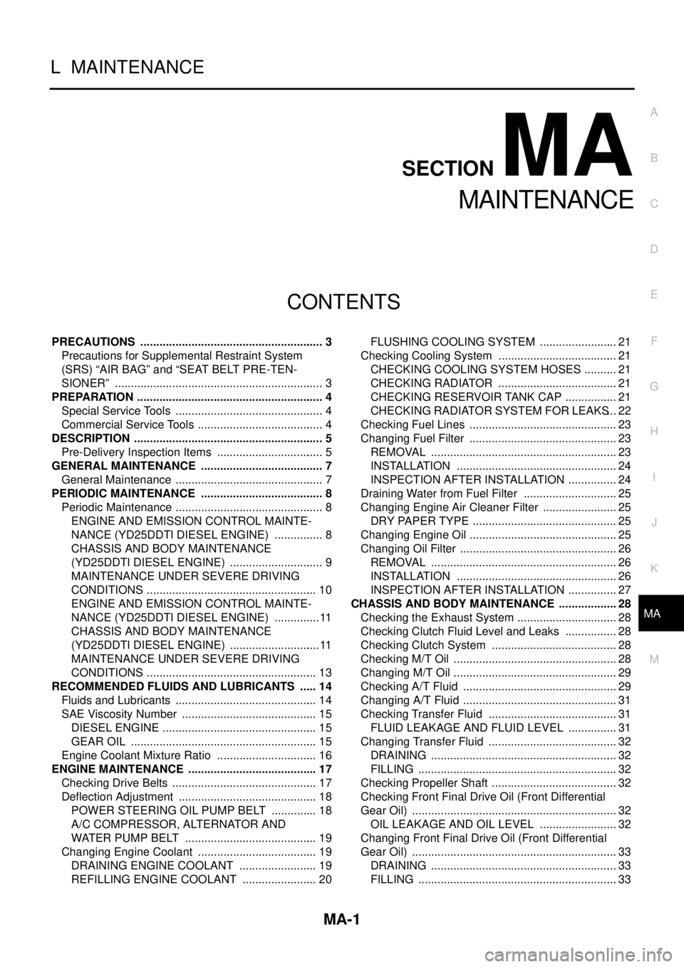
MA-1
MAINTENANCE
L MAINTENANCE
CONTENTS
C
D
E
F
G
H
I
J
K
M
SECTIONMA
A
B
MA
MAINTENANCE
PRECAUTIONS .......................................................... 3
Precautions for Supplemental Restraint System
(SRS)“AIRBAG”and“SEATBELTPRE-TEN-
SIONER” .................................................................. 3
PREPARATION ........................................................... 4
Special Service Tools ............................................... 4
Commercial Service Tools ........................................ 4
DESCRIPTION ............................................................ 5
Pre-Delivery Inspection Items .................................. 5
GENERAL MAINTENANCE ....................................... 7
General Maintenance ............................................... 7
PERIODIC MAINTENANCE ....................................... 8
Periodic Maintenance ............................................... 8
ENGINE AND EMISSION CONTROL MAINTE-
NANCE (YD25DDTI DIESEL ENGINE) ................ 8
CHASSIS AND BODY MAINTENANCE
(YD25DDTI DIESEL ENGINE) .............................. 9
MAINTENANCE UNDER SEVERE DRIVING
CONDITIONS ...................................................... 10
ENGINE AND EMISSION CONTROL MAINTE-
NANCE (YD25DDTI DIESEL ENGINE) ............... 11
CHASSIS AND BODY MAINTENANCE
(YD25DDTI DIESEL ENGINE) ............................. 11
MAINTENANCE UNDER SEVERE DRIVING
CONDITIONS ...................................................... 13
RECOMMENDED FLUIDS AND LUBRICANTS ...... 14
Fluids and Lubricants ............................................. 14
SAE Viscosity Number ........................................... 15
DIESEL ENGINE ................................................. 15
GEAR OIL ........................................................... 15
Engine Coolant Mixture Ratio ................................ 16
ENGINE MAINTENANCE ......................................... 17
Checking Drive Belts .............................................. 17
Deflection Adjustment ............................................ 18
POWER STEERING OIL PUMP BELT ............... 18
A/C COMPRESSOR, ALTERNATOR AND
WATER PUMP BELT .......................................... 19
Changing Engine Coolant ...................................... 19
DRAINING ENGINE COOLANT ......................... 19
REFILLING ENGINE COOLANT ........................ 20FLUSHING COOLING SYSTEM ......................... 21
Checking Cooling System ...................................... 21
CHECKING COOLING SYSTEM HOSES ........... 21
CHECKING RADIATOR ...................................... 21
CHECKING RESERVOIR TANK CAP ................. 21
CHECKING RADIATOR SYSTEM FOR LEAKS... 22
Checking Fuel Lines ............................................... 23
Changing Fuel Filter ............................................... 23
REMOVAL ........................................................... 23
INSTALLATION ................................................... 24
INSPECTION AFTER INSTALLATION ................ 24
Draining Water from Fuel Filter .............................. 25
Changing Engine Air Cleaner Filter ........................ 25
DRY PAPER TYPE .............................................. 25
Changing Engine Oil ............................................... 25
Changing Oil Filter .................................................. 26
REMOVAL ........................................................... 26
INSTALLATION ................................................... 26
INSPECTION AFTER INSTALLATION ................ 27
CHASSIS AND BODY MAINTENANCE ................... 28
Checking the Exhaust System ................................ 28
Checking Clutch Fluid Level and Leaks ................. 28
Checking Clutch System ........................................ 28
Checking M/T Oil .................................................... 28
Changing M/T Oil .................................................... 29
Checking A/T Fluid ................................................. 29
Changing A/T Fluid ................................................. 31
Checking Transfer Fluid ......................................... 31
FLUID LEAKAGE AND FLUID LEVEL ................ 31
Changing Transfer Fluid ......................................... 32
DRAINING ........................................................... 32
FILLING ............................................................... 32
Checking Propeller Shaft ........................................ 32
Checking Front Final Drive Oil (Front Differential
Gear Oil) ................................................................. 32
OIL LEAKAGE AND OIL LEVEL ......................... 32
Changing Front Final Drive Oil (Front Differential
Gear Oil) ................................................................. 33
DRAINING ........................................................... 33
FILLING ............................................................... 33