2005 NISSAN NAVARA oil change
[x] Cancel search: oil changePage 2289 of 3171

MA-14
RECOMMENDED FLUIDS AND LUBRICANTS
RECOMMENDED FLUIDS AND LUBRICANTS
PFP:00000
Fluids and LubricantsELS001JA
*1: For further details, see “SAE Viscosity Number”.
*2: Never use API CG-4.
*3: Use Genuine NISSAN Anti-freeze Coolant (L250) or equivalent in its quality, in order to avoid possible aluminum corrosion within the
engine cooling system caused by the use of non-genuine engine coolant.
Note that any repairs for the incidents within the engine cooling system while using non-genuine engine coolant may not be
covered by the warranty even if such incidents occurred during the warranty period.
*4: Contact a Nissan dealership for more information regarding suitable fluids, including recommended brand(s) of DEXRON
™III/MER-
CON™ Automatic Transmission Fluid.
*5:Using automatic transmission fluid other than Genuine NISSAN ATF Matic Fluid J will cause deterioration in driveability
and automatic transmission durability, and may damage the automatic transmission, which is not covered by the warranty.
*6: DEXRON™III type ATF can be used.
*7: Never mix different types of fluids (DOT 3 and DOT 4).Capacity (Approximate)
Recommended Fluids/Lubricants
Liter Imp measure
Engine oil
Drain and refillWith oil filter change 7.6 6-5/8 qt
lDiesel engine
API CF-4*1, *2
ACEA B1, B3, B4, B5*1 Without oil filter change 7.1 6-1/4 qt
Dry engine (engine overhaul) 7.9 7 qt
Cooling sys-
tem (with res-
ervoir)LHD models 9.9 8-3/4 qt
lGenuine NISSAN Anti-freeze Coolant (L250) or
equivalent in its quality*3 RHD models 10.2 9 qt
Reservoir tank 0.8 3/4 qt
Manual transmission gear oil2WD 3.99 7 pt
lGenuine NISSAN gear oil or API GL-4, Viscosity
SAE 75W-85 or 75W-90
4WD 4.32 7-5/8 pt
Transfer fluid 2.0 1-3/4 qt
lGenuine NISSAN ATF or equivalent*4
Differential gear oilFront 0.85 1-1/2 pt
lStandard differential gear:
Gear Oil Hypoid LSD (Part No.: KLD31-8090403)
or API GL-5, Viscosity SAE 80W-90*1
lLimited-slip differential (LSD) gear:
Gear Oil Hypoid LSD (Part No. KLD31-8090403)
or equivalent Rear 2.01 3-1/2 pt
Automatic transmission fluid 10.3 9-1/8 qt Genuine NISSAN ATF Matic Fluid J*5
Power steering fluid — — Genuine NISSAN PSF or equivalent*6
Brake and clutch fluid — —
lDOT 3 or DOT 4 (US FMVSS No. 116)*7
Multi-purpose grease — — NLGI No. 2 (Lithium soap base)
Page 2301 of 3171
MA-26
ENGINE MAINTENANCE
CAUTION:
Be sure to clean drain plug and install with new washer.
6. Refill with new engine oil.
Engine oil specification and viscosity:
Refer toMA-14, "
RECOMMENDED FLUIDS AND LUBRICANTS".
Engine oil capacity (Approximate):
Unit: (lmp qt)
CAUTION:
lWhen filling engine oil, do not pull out oil level gauge.
lThe refill capacity depends on the engine oil temperature and drain time. Use these specifica-
tions for reference only.
lAlways use the oil level gauge to determine when the proper amount of engine oil is in the
engine.
7. Warm up engine and check area around drain plug and oil filter for oil leakage.
8. Stop engine and wait for 10 minutes.
9. Check the engine oil level. Refer toLU-5, "
ENGINE OIL LEVEL".
Changing Oil FilterELS001JY
REMOVAL
1. Remove engine undercover middle.
2. Place a pan to catch the engine oil under the lower part of drain hose outlet before removing oil filter.
3. Using the oil filter wrench, remove oil filter.
CAUTION:
lBe careful not to get burned when engine and engine oil are hot.
lWhen removing, prepare a shop cloth to absorb any engine oil leakage or spillage.
lDo not allow engine oil to adhere to drive belts.
lCompletely wipe off any engine oil that adhere to engine and vehicle.
lOil filter is provided with a relief valve. Use Genuine NISSAN Oil Filter or equivalent.
INSTALLATION
1. Remove foreign materials adhering to the oil filter installation surface.
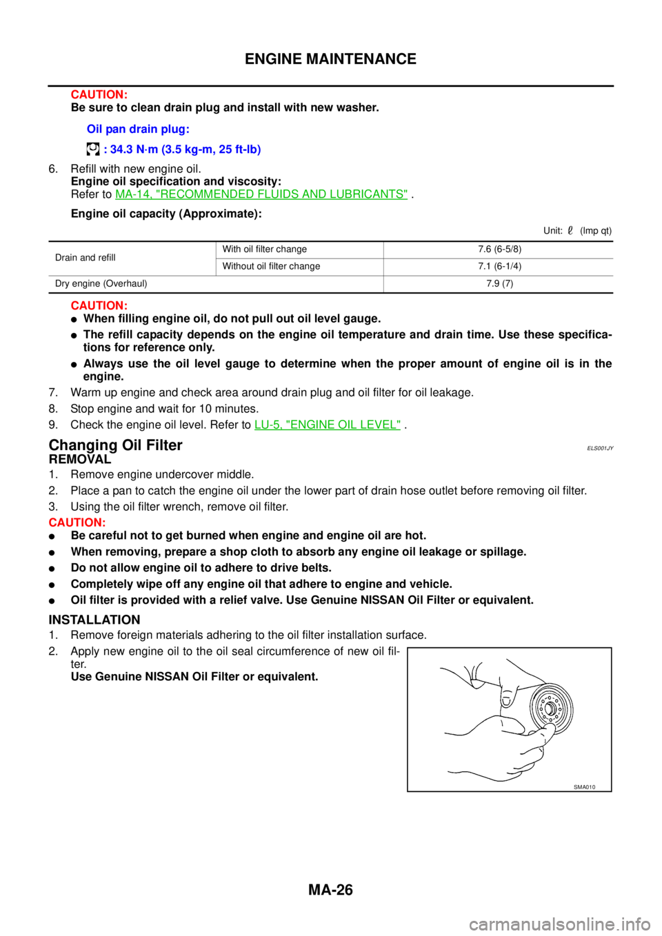
2. Apply new engine oil to the oil seal circumference of new oil fil-
ter.
Use Genuine NISSAN Oil Filter or equivalent.Oil pan drain plug:
: 34.3 N·m (3.5 kg-m, 25 ft-lb)
Drain and refillWith oil filter change 7.6 (6-5/8)
Without oil filter change 7.1 (6-1/4)
Dry engine (Overhaul)7.9 (7)
SMA010
Page 2316 of 3171

SERVICE DATA AND SPECIFICATIONS (SDS)
MA-41
C
D
E
F
G
H
I
J
K
MA
B
MA
SERVICE DATA AND SPECIFICATIONS (SDS)PFP:00030
Standard and LimitELS001J8
BELT DEFLECTION
*: When engine is cold.
RESERVOIR TANK
Unit:kPa(bar,kg/cm2, psi)
ENGINE COOLANT CAPACITY (APPROXIMATE)
Unit: (lmp qt)
ENGINE OIL CAPACITY (APPROXIMATE)
Unit: (lmp qt) Applied beltBelt deflection with 98 N (10 kg, 22 lb) force applied* mm (in)
New Adjusted Limit for re-adjusting
A/C compressor, alternator and water
pump belt2.9 - 3.4 (0.114 - 0.134) 3.9 - 4.4 (0.154 - 0.173) 8.5 (0.335)
Power steering oil pump belt 4.6 - 5.4 (0.181 - 0.213) 7.1 - 7.7 (0.280 - 0.303) 11.3 (0.445)
Cap relief pressureStandard 98.2 - 117.8 (0.98 - 1.18, 1.0 - 1.2, 14 - 17)
Limit 59 (0.59, 0.6, 9)
Leakage test pressure 157 (1.57, 1.6, 23)
Engine coolant capacity (With reser-
voir tank at “MAX” level)LHD models 9.9 (8-3/4)
RHD models 10.2 (9)
Reservoir tank coolant capacity (At “MAX” level) 0.8 (3/4)
Drain and refillWith oil filter change 7.6 (6-5/8)
Without oil filter change 7.1 (6-1/4)
Dry engine (Overhaul)7.9 (7)
Page 2403 of 3171
MTC-16
PREPARATION
PREPARATION
PFP:00002
Special Service ToolsEJS0062C
The actual shapes of Kent-Moore tools may differ from those of special service tools illustrated here.
HFC-134a (R-134a) Service Tools and EquipmentEJS0062D
Never mix HFC-134a (R-134a) refrigerant and/or its specified lubricant with CFC-12 (R-12) refrigerant and/or
its lubricant.
Separate and non-interchangeable service equipment must be used for handling each type of refrigerant/lubri-
cant.
Refrigerant container fittings, service hose fittings and service equipment fittings (equipment which handles
refrigerant and/or lubricant) are different between CFC-12 (R-12) and HFC-134a (R-134a). This is to avoid
mixed use of the refrigerants/lubricant.
Adapters that convert one size fitting to another must never be used: refrigerant/lubricant contamination will
occur and compressor malfunction will result.
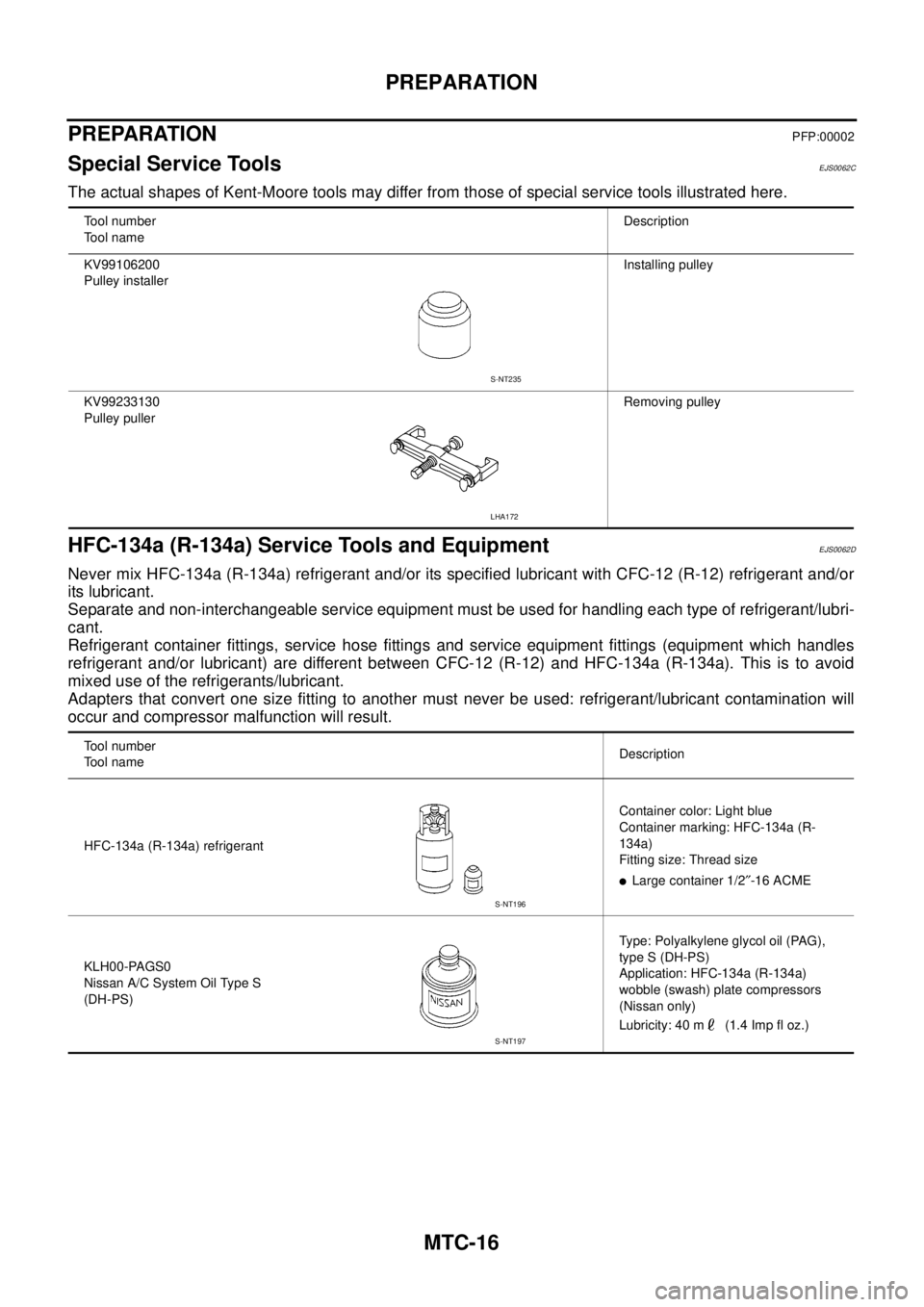
Tool number
Tool nameDescription
KV99106200
Pulley installerInstalling pulley
KV99233130
Pulley pullerRemoving pulley
S-NT235
LHA172
Tool number
Tool nameDescription
HFC-134a (R-134a) refrigerantContainer color: Light blue
Container marking: HFC-134a (R-
134a)
Fitting size: Thread size
lLarge container 1/2²-16 ACME
KLH00-PAGS0
Nissan A/C System Oil Type S
(DH-PS)Type: Polyalkylene glycol oil (PAG),
type S (DH-PS)
Application: HFC-134a (R-134a)
wobble (swash) plate compressors
(Nissan only)
Lubricity: 40 m (1.4 Imp fl oz.)
S-NT196
S-NT197
Page 2705 of 3171

RFD-2
DIFFERENTIAL LOCK CONTROL UNIT ............ 42
DIFFERENTIAL LOCK MODE SWITCH ............. 42
DIFF LOCK INDICATOR LAMP ........................... 42
System Diagram ..................................................... 43
COMPONENTS FUNCTION DESCRIPTION ...... 43
CAN Communication .............................................. 43
SYSTEM DESCRIPTION .................................... 43
TROUBLE DIAGNOSIS ............................................ 44
Fail-safe Function ................................................... 44
How to Perform Trouble Diagnosis ......................... 44
BASIC CONCEPT ............................................... 44
Location of Electrical Parts ..................................... 45
Wiring Diagram — DIFLOC — ................................ 46
Trouble Diagnosis Chart for Symptoms .................. 48
Differential Lock Control Unit Input/Output Signal
Reference Values ................................................... 48
DIFFERENTIAL LOCK CONTROL UNIT
INSPECTION TABLE .......................................... 48
CONSULT-II Function (DIFF LOCK) ....................... 50
FUNCTION .......................................................... 50
CONSULT-II SETTING PROCEDURE ................ 50
SELF-DIAG RESULTS MODE ............................. 51
DATA MONITOR MODE ...................................... 53
TROUBLE DIAGNOSIS FOR SYSTEM .................... 54
Power Supply Circuit For Differential Lock Control
Unit ......................................................................... 54
CONSULT-II REFERENCE VALUE IN DATA
MONITOR MODE ................................................ 54
DIFFERENTIAL LOCK CONTROL UNIT TER-
MINALS AND REFERENCE VALUE ................... 54
DIAGNOSTIC PROCEDURE .............................. 55
Differential Lock Control Unit .................................. 56
DIAGNOSTIC PROCEDURE .............................. 56
Differential Lock Mode Switch ................................ 56
CONSULT-II REFERENCE VALUE IN DATA
MONITOR MODE ................................................ 56
DIFFERENTIAL LOCK CONTROL UNIT TER-
MINALS AND REFERENCE VALUE ................... 56
DIAGNOSTIC PROCEDURE .............................. 57
COMPONENT INSPECTION .............................. 59
Differential Lock Position Switch ............................. 60
CONSULT-II REFERENCE VALUE IN DATA
MONITOR MODE ................................................ 60
DIFFERENTIAL CONTROL UNIT TERMINALS
AND REFERENCE VALUE ................................. 60
DIAGNOSTIC PROCEDURE .............................. 61
COMPONENT INSPECTION .............................. 63
Differential Lock Solenoid Relay ............................. 63
CONSULT-II REFERENCE VALUE IN DATA
MONITOR MODE ................................................ 63DIAGNOSTIC PROCEDURE ............................... 63
Differential Lock Solenoid ....................................... 64
CONSULT-II REFERENCE VALUE IN DATA
MONITOR MODE ................................................ 64
DIFFERENTIAL LOCK CONTROL UNIT TER-
MINALS AND REFERENCE VALUE ................... 64
DIAGNOSTIC PROCEDURE ............................... 65
COMPONENT INSPECTION ............................... 68
ABS System ............................................................ 68
DIAGNOSTIC PROCEDURE ............................... 68
CAN Communication Line ....................................... 69
DIAGNOSTIC PROCEDURE ............................... 69
TROUBLE DIAGNOSIS FOR SYMPTOMS .............. 70
DIFF LOCK Indicator Lamp Does Not Turn ON ...... 70
DIAGNOSTIC PROCEDURE ............................... 70
DIFF LOCK Indicator Lamp Does Not Change ....... 73
DIAGNOSTIC PROCEDURE ............................... 73
DIFF LOCK Indicator Lamp Sometimes Flashes .... 74
DIAGNOSTIC PROCEDURE ............................... 74
DIFFERENTIAL LOCK CONTROL UNIT .................. 76
Removal and Installation ......................................... 76
REMOVAL ............................................................ 76
INSTALLATION .................................................... 76
FRONT OIL SEAL ..................................................... 77
Removal and Installation ......................................... 77
REMOVAL ............................................................ 77
INSTALLATION .................................................... 78
CARRIER COVER ..................................................... 80
Removal and Installation ......................................... 80
REMOVAL ............................................................ 80
INSTALLATION .................................................... 80
REAR FINAL DRIVE ASSEMBLY ............................. 81
Removal and Installation ......................................... 81
REMOVAL ............................................................ 81
INSTALLATION .................................................... 81
Disassembly and Assembly .................................... 82
COMPONENTS ................................................... 82
ASSEMBLY INSPECTION AND ADJUSTMENT...83
DISASSEMBLY .................................................... 86
INSPECTION AFTER DISASSEMBLY ................ 90
SELECTION ADJUSTING WASHERS ................ 90
ASSEMBLY .......................................................... 91
SERVICE DATA AND SPECIFICATIONS (SDS) ....100
General Specifications ..........................................100
Inspection and Adjustment ....................................100
PRELOAD TORQUE .........................................100
BACKLASH ........................................................100
COMPANION FLANGE RUNOUT .....................100
SELECTIVE PARTS ..........................................101
Page 2969 of 3171

TF-2
DIAGNOSTIC PROCEDURE .............................. 53
COMPONENT INSPECTION .............................. 54
Transfer Control Unit .............................................. 54
DIAGNOSTIC PROCEDURE .............................. 54
Output Shaft Revolution Signal (TCM) ................... 55
DIAGNOSTIC PROCEDURE .............................. 55
Vehicle Speed Sensor (ABS) .................................. 55
DIAGNOSTIC PROCEDURE .............................. 55
4LO Switch ............................................................. 56
CONSULT-II REFERENCE VALUE IN DATA
MONITOR MODE ................................................ 56
TRANSFER CONTROL UNIT TERMINALS AND
REFERENCE VALUE .......................................... 56
DIAGNOSTIC PROCEDURE .............................. 57
COMPONENT INSPECTION .............................. 59
4WD Shift Switch .................................................... 59
CONSULT-II REFERENCE VALUE IN DATA
MONITOR MODE ................................................ 59
TRANSFER CONTROL UNIT TERMINALS AND
REFERENCE VALUE .......................................... 59
DIAGNOSTIC PROCEDURE .............................. 60
COMPONENT INSPECTION .............................. 62
Wait Detection Switch ............................................. 63
CONSULT-II REFERENCE VALUE IN DATA
MONITOR MODE ................................................ 63
TRANSFER CONTROL UNIT TERMINALS AND
REFERENCE VALUE .......................................... 63
DIAGNOSTIC PROCEDURE .............................. 64
COMPONENT INSPECTION .............................. 66
PNP Switch Signal (TCM) ...................................... 66
DIAGNOSTIC PROCEDURE .............................. 66
Actuator Motor ........................................................ 67
CONSULT-II REFERENCE VALUE IN DATA
MONITOR MODE ................................................ 67
TRANSFER CONTROL UNIT TERMINALS AND
REFERENCE VALUE .......................................... 67
DIAGNOSTIC PROCEDURE .............................. 68
COMPONENT INSPECTION .............................. 74
Actuator Position Switch ......................................... 75
CONSULT-II REFERENCE VALUE IN DATA
MONITOR MODE ................................................ 75
TRANSFER CONTROL UNIT TERMINALS AND
REFERENCE VALUE .......................................... 75
DIAGNOSTIC PROCEDURE .............................. 76
Transfer Control Device .......................................... 78
CONSULT-II REFERENCE VALUE IN DATA
MONITOR MODE ................................................ 78
TRANSFER CONTROL UNIT TERMINALS AND
REFERENCE VALUE .......................................... 78
DIAGNOSTIC PROCEDURE .............................. 79
Engine Speed Signal (ECM) ................................... 81
DIAGNOSTIC PROCEDURE .............................. 81
CAN Communication Line ...................................... 82
DIAGNOSTIC PROCEDURE .............................. 82
ATP Switch ............................................................. 82
CONSULT-II REFERENCE VALUE IN DATA
MONITOR MODE ................................................ 82
TRANSFER CONTROL UNIT TERMINALS ANDREFERENCE VALUE .......................................... 82
DIAGNOSTIC PROCEDURE ............................... 83
COMPONENT INSPECTION ............................... 85
Park/Neutral Position Switch ................................... 85
TRANSFER CONTROL UNIT TERMINALS AND
REFERENCE VALUE .......................................... 85
DIAGNOSTIC PROCEDURE ............................... 85
COMPONENT INSPECTION ............................... 87
TROUBLE DIAGNOSIS FOR SYMPTOMS .............. 88
4WD Shift Indicator Lamp and 4LO Indicator Lamp
Do Not Turn ON ...................................................... 88
SYMPTOM: .......................................................... 88
DIAGNOSTIC PROCEDURE ............................... 89
4WD Warning Lamp Does Not Turn ON ................. 91
SYMPTOM: .......................................................... 91
DIAGNOSTIC PROCEDURE ............................... 92
4WD Shift Indicator Lamp or 4LO Indicator Lamp
Does Not Change ................................................... 94
SYMPTOM: .......................................................... 94
DIAGNOSTIC PROCEDURE ............................... 95
ATP Warning Lamp Does Not Turn ON .................. 96
SYMPTOM: .......................................................... 96
DIAGNOSTIC PROCEDURE ............................... 96
4WD Shift Indicator Lamp Repeats Flashing .......... 98
SYMPTOM: .......................................................... 98
DIAGNOSTIC PROCEDURE ............................... 98
4WD Warning Lamp Flashes Slowly ....................... 99
SYMPTOM: .......................................................... 99
DIAGNOSTIC PROCEDURE ............................... 99
TRANSFER CONTROL UNIT .................................100
Removal and Installation .......................................100
REMOVAL ..........................................................100
INSTALLATION ..................................................100
FRONT OIL SEAL ...................................................101
Removal and Installation .......................................101
REMOVAL ..........................................................101
INSTALLATION ..................................................102
REAR OIL SEAL .....................................................103
Removal and Installation .......................................103
REMOVAL ..........................................................103
INSTALLATION ..................................................103
TRANSFER CONTROL DEVICE ............................105
Removal and Installation .......................................105
REMOVAL ..........................................................105
INSTALLATION ..................................................105
AIR BREATHER HOSE ...........................................107
Removal and Installation .......................................107
A/T MODELS .....................................................107
M/T MODELS .....................................................109
TRANSFER ASSEMBLY ......................................... 111
Removal and Installation ....................................... 111
REMOVAL .......................................................... 111
INSTALLATION ..................................................112
Disassembly and Assembly ..................................112
COMPONENTS .................................................112
DISASSEMBLY ..................................................114
INSPECTION AFTER DISASSEMBLY ..............119
ASSEMBLY ........................................................120