Page 35 of 364
ENGINE – ENGINE ASSY
11-29
Removal procedure
1. Ignition coil connector
2. O
2sensor connector
3. Oil feeder control valve connector
4. Crank angle sensor connector
5. Manifold absolute pressure sensor
connector
6. Fuel pressure solenoid valve connector
7. Knock sensor connector
8. Purge control solenoid valve connector
9. Throttle position connector
10. Injector connector11.Exhaust cam position sensor connector
12. Inlet cam position sensor connector
13. Water temperature gauge unit connector
14. Joint control harness and transmission
harness
15. Water temperature sensor connector
16. Alternator connector and terminal
17. Secondary air control solenoid valve
connector
18. Engine oil pressure switch connector
19. Drive belt
� �
A� �
Page 72 of 364
ENGINE COOLING – WATER PUMP14-2
Water pump
Removal and fitting
Jobs to be completed before removal and after fitting
•Draining and refilling of the coolant
•Removal and refitting of the timing belt (Ref Section 11)
Removal procedure
1. Alternator bracket
2. Water pump
3. Water pump gasket
4. O-ring
Fitting guidelines
� �
A� �
Fitting the O-ring
Fit the O-ring into the O-ring groove at the end of the water inlet
pipe, and insert it into the water pump after moistening with water
the places where the O-ring will make contact with the water pump.
Caution
Ensure that absolutely no engine oil, or other type of grease,
gets onto the O-ring.
Positions for fitting different sized bolts
Nominal diameter and nominal length (mm)
� �
A� �
water pump
O-ring
water inlet pipe
Page 85 of 364

ENGINE ELECTRICAL – CHARGING SYSTEM
16-1
SECTION 16
ENGINE ELECTRICAL
CONTENTS
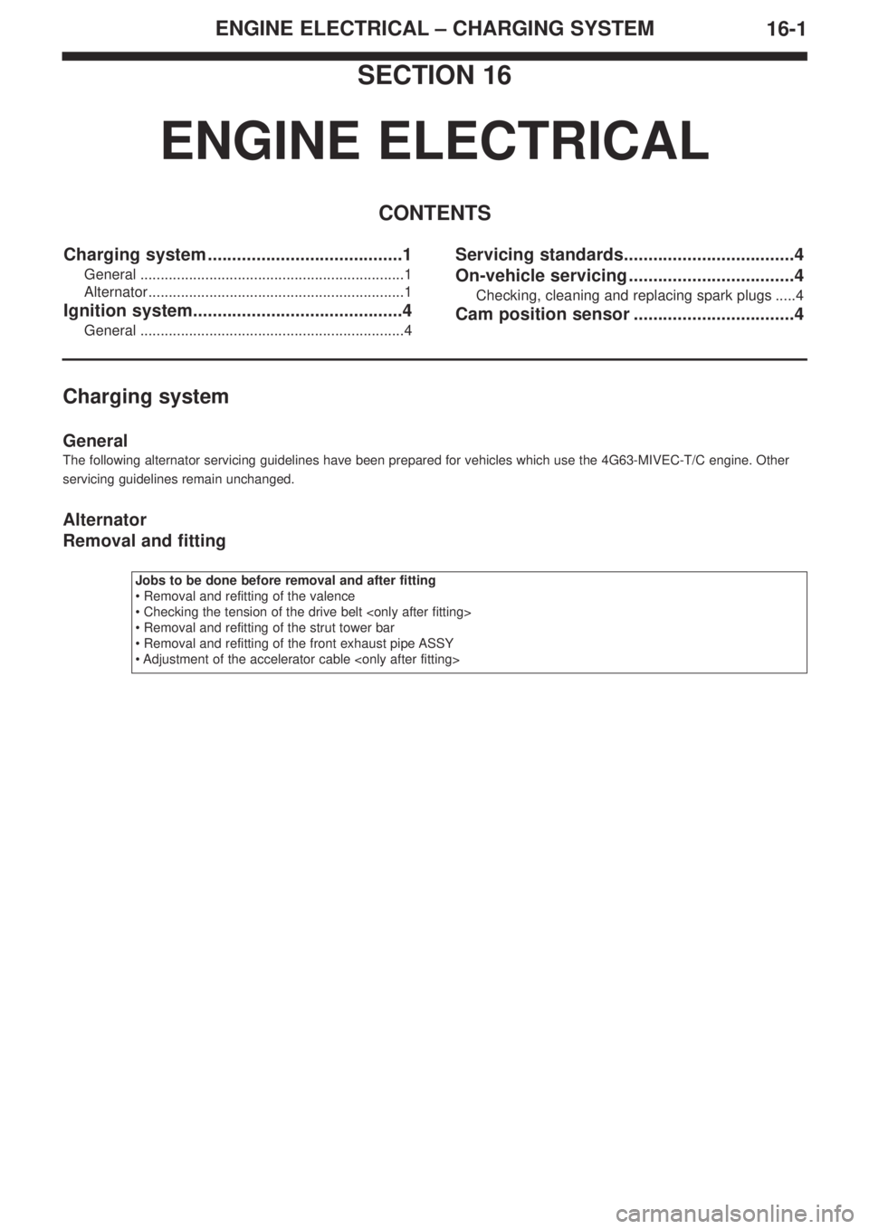
Charging system ........................................1
General .................................................................1
Alternator...............................................................1
Ignition system...........................................4
General .................................................................4
Servicing standards...................................4
On-vehicle servicing ..................................4
Checking, cleaning and replacing spark plugs .....4
Cam position sensor .................................4
Charging system
General
The following alternator servicing guidelines have been prepared for vehicles which use the 4G63-MIVEC-T/C engine. Other
servicing guidelines remain unchanged.
Alternator
Removal and fitting
Jobs to be done before removal and after fitting
• Removal and refitting of the valence
• Checking the tension of the drive belt
• Removal and refitting of the strut tower bar
• Removal and refitting of the front exhaust pipe ASSY
• Adjustment of the accelerator cable
Page 86 of 364
ENGINE ELECTRICAL – CHARGING SYSTEM16-2
Removal procedure
1. Injector connector
2. Accelerator cable connection
3. Delivery pipe, injector, and fuel pressure
regulator ASSY
4. Insulator
5. Insulator
6. Fuel pressure solenoid valve connector
7. Fuel pressure solenoid valve ASSY
8. Knock sensor connector
9. Purge control solenoid valve connector10. Purge control solenoid valve ASSY
11.Oil level gauge and guide ASSY
12. O-ring
13. Drive belt
14. Alternator connector and terminal
• Engine mount
15. Alternator
16. Water pump pulley
17. O
2sensor connector
18. Alternator bracket
(engine oil)
� �
A� ��
�
B� �
� �
C� �
Page 87 of 364

ENGINE ELECTRICAL – CHARGING SYSTEM
16-3
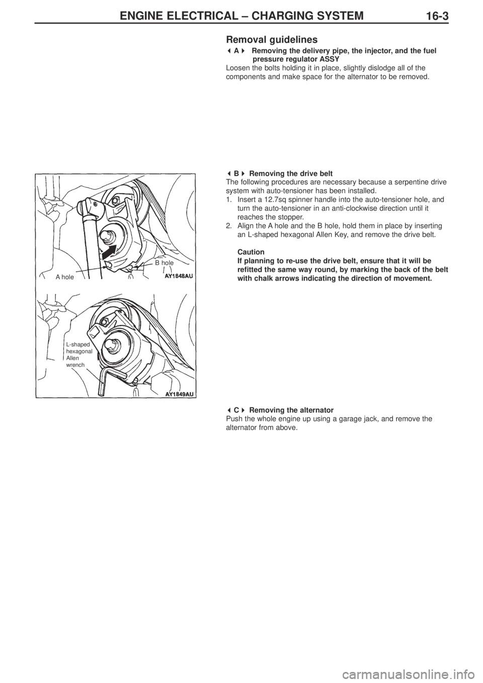
Removal guidelines
� �
A� �
Removing the delivery pipe, the injector, and the fuel
pressure regulator ASSY
Loosen the bolts holding it in place, slightly dislodge all of the
components and make space for the alternator to be removed.
� �
B� �
Removing the drive belt
The following procedures are necessary because a serpentine drive
system with auto-tensioner has been installed.
1. Insert a 12.7sq spinner handle into the auto-tensioner hole, and
turn the auto-tensioner in an anti-clockwise direction until it
reaches the stopper.
2. Align the A hole and the B hole, hold them in place by inserting
an L-shaped hexagonal Allen Key, and remove the drive belt.
Caution
If planning to re-use the drive belt, ensure that it will be
refitted the same way round, by marking the back of the belt
with chalk arrows indicating the direction of movement.
� �
C� �
Removing the alternator
Push the whole engine up using a garage jack, and remove the
alternator from above.
AholeB hole
L-shaped
hexagonal
Allen
wrench
Page 108 of 364

Service Manual
4G6
FOREWORD
This manual contains information about the 4G6
DOHC engine. It only covers those points that are
different from the service manuals listed below.
Therefore, this manual should be used in conjunction
with the following manuals.
• 4G6 DOHC engine Service Manual (No. 1039G46)
• 4G6 DOHC engine Service Manual Supplement
(No.1039G63)
This manual is based on the engine specifications as of
March 2005. Please note that some engine details may
not match those given in this manual due to
subsequent changes in engine specifications. The units
shown in this manual are the standard international
SI units.
(However, conventional units are used for some figures
taken from existing documents)
If you have any opinions, requests or queries regarding
this manual, please write them down on the “Servicing
Comment Form” on the last page, and fax them to us.
March 2005
Mitsubishi Motor Corporation
This manual is printed on recycled paper.
CONTENTS
General Information . . . . . . . . . . . . . . . 4
Servicing Specification Values . . . . . . 4
Tightening torques . . . . . . . . . . . . . . . . 5
Sealants . . . . . . . . . . . . . . . . . . . . . . . . . 7
Alternator / Ignition system . . . . . . . . . 8
Timing belt . . . . . . . . . . . . . . . . . . . . . 10
Fuel system . . . . . . . . . . . . . . . . . . . . . 13
Secondary air system /
inlet manifold . . . . . . . . . . . . . . . . . . . 15
Exhaust manifold . . . . . . . . . . . . . . . . 16
Water pump / Water hose . . . . . . . . . 17
Rocker arm / Cam shaft . . . . . . . . . . . 18
Oil pump / Sump . . . . . . . . . . . . . . . . . 21
Pistons / Connecting rods . . . . . . . . . 22
Crank shaft / Cylinder block . . . . . . . 25
Turbocharger. . . . . . . . . . . . . . . . . . . . 27
DOHC
ENGINE
Page 112 of 364

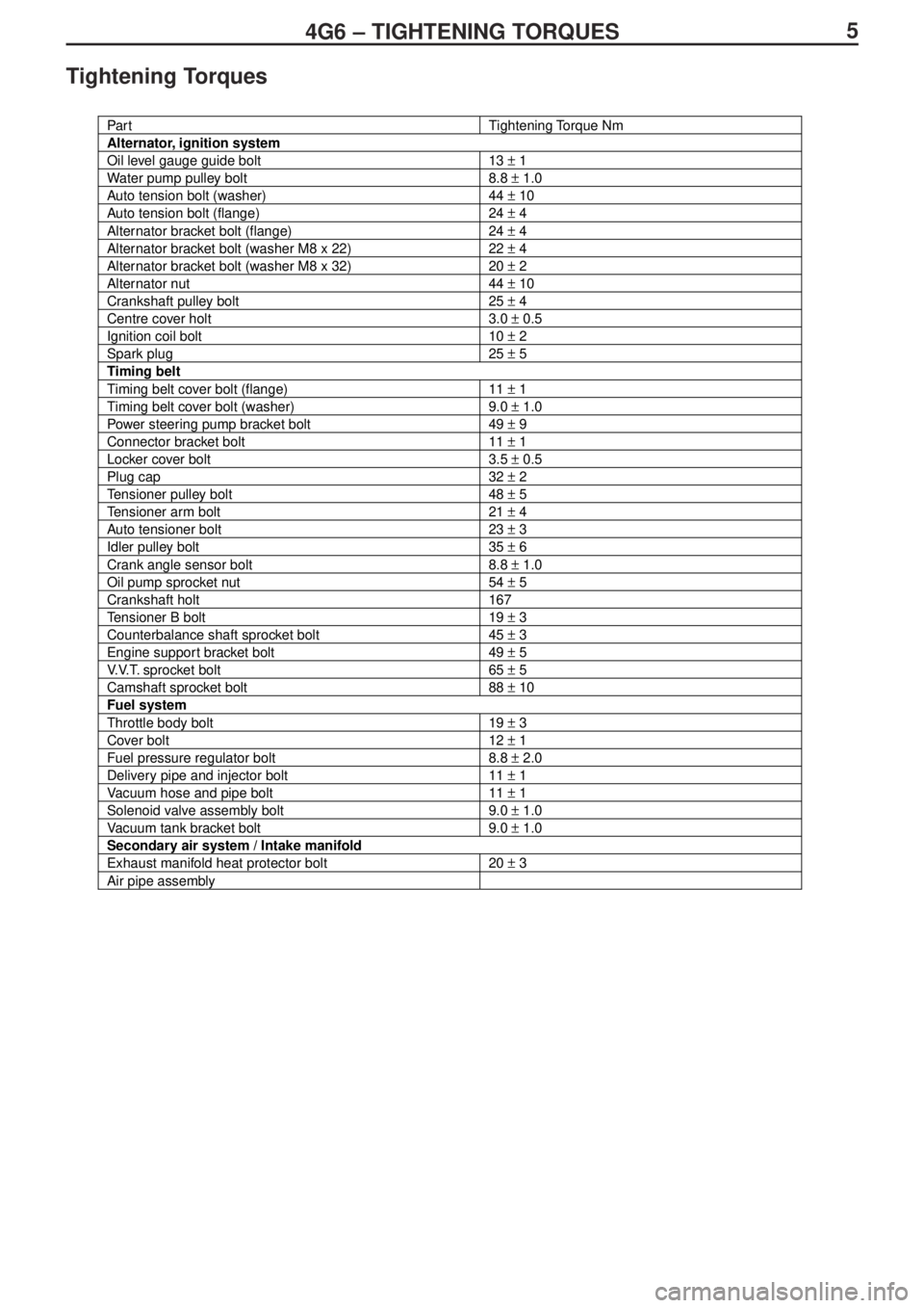
54G6 – TIGHTENING TORQUES
Tightening Torques
Par tTightening Torque Nm
Alternator, ignition system
Oil level gauge guide bolt13 ± 1
Water pump pulley bolt8.8 ± 1.0
Auto tension bolt (washer)44 ± 10
Auto tension bolt (flange)24 ± 4
Alternator bracket bolt (flange)24 ± 4
Alternator bracket bolt (washer M8 x 22)22 ± 4
Alternator bracket bolt (washer M8 x 32)20 ± 2
Alternator nut44 ± 10
Crankshaft pulley bolt25 ± 4
Centre cover holt3.0 ± 0.5
Ignition coil bolt10 ± 2
Spark plug25 ± 5
Timing belt
Timing belt cover bolt (flange)11 ± 1
Timing belt cover bolt (washer)9.0 ± 1.0
Power steering pump bracket bolt49 ± 9
Connector bracket bolt11 ± 1
Locker cover bolt3.5 ± 0.5
Plug cap32 ± 2
Tensioner pulley bolt48 ± 5
Tensioner arm bolt21 ± 4
Auto tensioner bolt23 ± 3
Idler pulley bolt35 ± 6
Crank angle sensor bolt8.8 ± 1.0
Oil pump sprocket nut54 ± 5
Crankshaft holt167
Tensioner B bolt19 ± 3
Counterbalance shaft sprocket bolt45 ± 3
Engine support bracket bolt49 ± 5
V.V.T. sprocket bolt65 ± 5
Camshaft sprocket bolt88 ± 10
Fuel system
Throttle body bolt19 ± 3
Cover bolt12 ± 1
Fuel pressure regulator bolt8.8 ± 2.0
Delivery pipe and injector bolt11 ± 1
Vacuum hose and pipe bolt11 ± 1
Solenoid valve assembly bolt9.0 ± 1.0
Vacuum tank bracket bolt9.0 ± 1.0
Secondary air system / Intake manifold
Exhaust manifold heat protector bolt20 ± 3
Air pipe assembly