Page 73 of 364

ENGINE COOLING – WATER HOSE AND PIPE
14-3
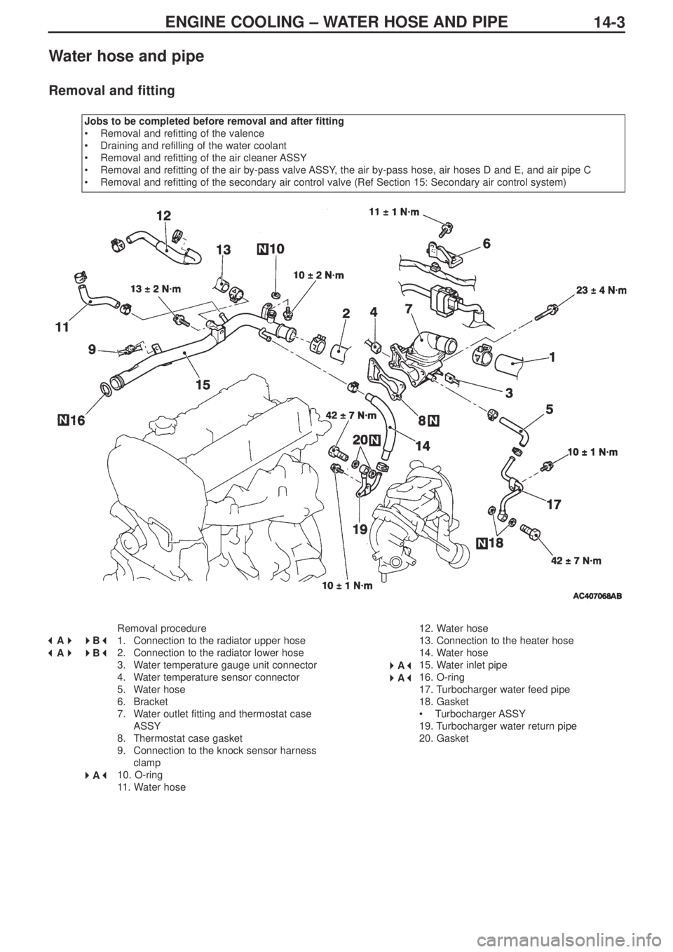
Water hose and pipe
Removal and fitting
Jobs to be completed before removal and after fitting
•Removal and refitting of the valence
•Draining and refilling of the water coolant
•Removal and refitting of the air cleaner ASSY
•Removal and refitting of the air by-pass valve ASSY, the air by-pass hose, air hoses D and E, and air pipe C
•Removal and refitting of the secondary air control valve (Ref Section 15: Secondary air control system)
Removal procedure
1. Connection to the radiator upper hose
2. Connection to the radiator lower hose
3. Water temperature gauge unit connector
4. Water temperature sensor connector
5. Water hose
6. Bracket
7. Water outlet fitting and thermostat case
ASSY
8. Thermostat case gasket
9. Connection to the knock sensor harness
clamp
10. O-ring
11. Water hose12. Water hose
13. Connection to the heater hose
14. Water hose
15. Water inlet pipe
16. O-ring
17. Turbocharger water feed pipe
18. Gasket
•Turbocharger ASSY
19. Turbocharger water return pipe
20. Gasket
� �
A� �
�
�
B� �
� �
A� �
�
�
B� �
� �
A� �
�
�
A� �
� �
A� �
Page 74 of 364

ENGINE COOLING – WATER HOSE AND PIPE14-4
Removal guidelines
� �
A� �
Removing the radiator upper hose and the radiator
lower hose
Mark the radiator hose and the hose clamp with indicator marks
and then remove the radiator hose.
Fitting guidelines
� �
A� �
Fitting the O-ring and the water inlet pipe
Fit the O-ring into the groove at the end of the water inlet pipe, and
insert it after moistening with water the places where the O-ring and
the water inlet pipe will be in contact.
Caution
Ensure that absolutely no engine oil, or other type of grease,
gets onto the O-ring.
� �
B� �
Connecting the radiator lower hose and the radiator
upper hose
1. Insert the hose as far as the protrusion on the water inlet pipe
and the water outlet fitting.
2. Match up the indicator marks on the radiator hose and the hose
clamp, and fit the radiator hose.
indicator marks
water pump and
thermostat case
O-ring
water inlet pipe
protrusion
water inlet pipe and
water outlet pipe fittingindicator marks
Page 75 of 364

INTAKE & EXHAUST – GENERAL, SERVICING STANDARDS, SPECIAL TOOLS,
ON-VEHICLE SERVICING15-1
SECTION 15
INTAKE & EXHAUST
CONTENTS
General................................................................................1
Servicing standards ..........................................................1
Special tools.......................................................................1
On-vehicle servicing..........................................................1
Turbocharger super charging pressure check ...............1Inter-cooler water spray ....................................................2
Secondary air control system ..........................................4
Inlet manifold .....................................................................5
Exhaust manifold and turbocharger ................................8
General
The following servicing guidelines have been prepared for vehicles which use the 4G63-MIVEC-T/C engine. Other servicing
guidelines remain unchanged.
• Changes to the turbocharger supercharging pressure
• Changes to the inter-cooler water spray hose
• Changes to the secondary air control valve
• Changes to the inlet manifold
• Changes to the exhaust manifold and the turbocharger
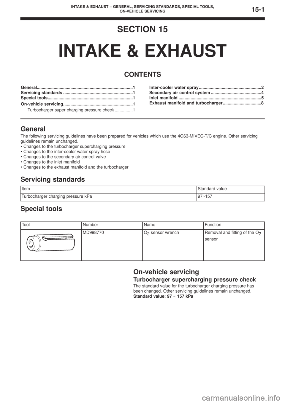
Special tools
On-vehicle servicing
Turbocharger supercharging pressure check
The standard value for the turbocharger charging pressure has
been changed. Other servicing guidelines remain unchanged.
Standard value: 97 ~ 157 kPa
ItemStandard value
Turbocharger charging pressure kPa97~157
Servicing standards
ToolNumberNameFunction
MD998770O
2sensor wrenchRemoval and fitting of the O
2
sensor
Page 79 of 364
INTAKE & EXHAUST – SECONDARY AIR CONTROL SYSTEM, INLET MANIFOLD15-5
Fitting guidelines
� �
A� �
Fitting the gasket
Fit the gasket so that the protruding part points in the direction
shown in the diagram.
Inlet manifold
Removal and fitting
Jobs to be completed before removal and
after fitting
•Take measures to prevent fuel leaking (only
before removal)
•Removal and refitting of the valence (Ref
Section 15: Front bumper)
•Draining and refilling the coolant
•Removal and refitting of the air duct•Removal and refitting of the strut tower bar
•Removal and refitting of the throttle body
•Removal and refitting of the secondary air
control valve (Ref P15-4)
•Removal and refitting of the cross member bar
•Removal and refitting of the front exhaust pipe
protruding
part
(engine oil)
(engine oil)
Page 81 of 364

INTAKE & EXHAUST – INLET MANIFOLD
15-7
Removal procedure
24. Knock sensor connector
25. Purge control solenoid valve ASSY
26. Vacuum hose
27. Fuel pressure solenoid valve ASSY
28. PCV hose
•Alternator (Ref Section 16: Alternator)
29. Secondary air control solenoid valve
connector
30. Vacuum tank, ACV solenoid valve,
vacuum hose & pipe ASSY31. Inlet manifold stay
32. Cover
33. Gasket
34. Harness connection
35. Crank angle sensor connector
36. Alternator bracket
37. Inlet manifold
38. Inlet manifold gasket
Removal guidelines
� �
A� �
Removal of the delivery pipe, the injector and the fuel
pressure regulator ASSY
Remove the deliver pipe, with the injector and the fuel pressure
regulator intact.
Caution
When removing the delivery pipe, be careful not to drop the
injector.
Fitting guidelines
� �
A� �
Connecting the O-ring and the fuel high pressure hose
1. Apply a small quantity of fresh engine oil to the O-ring, and
insert it into the delivery pipe without damaging the O-ring.
2. Check that the high pressure hose can be turned smoothly. If it
cannot be turned smoothly there is a possibility that it is biting
into the O-ring, so remove the high pressure hose and check for
any damage to the O-ring. If the O-ring is undamaged, reinsert it
into the delivery pipe and check once more whether the hose
can be turned smoothly.
3. Tighten the mounting bolt to the specified torque.
Tightening torque: 5.0 ± 1.0 N·m
Page 82 of 364
INTAKE & EXHAUST – EXHAUST MANIFOLD & TURBOCHARGER15-8
Exhaust manifold and turbocharger
Removal and fitting
Jobs to be completed before removal and after
fitting
• Removal and refitting of the valence
• Removal and refitting of the radiator
• Removal and refitting of the air intake hose and
air hose A• Removal and refitting of the cross member bar
• Removal and refitting of the front exhaust pipe
• Draining and refilling of the engine oil
Page 84 of 364
INTAKE & EXHAUST – EXHAUST MANIFOLD15-10
� �
B� �
Fitting the air outlet fitting gasket
Fit the gasket so that the protruding part is in the position located in
the diagram.
� �
C� �
Fitting the oil return pipe gasket (oil pan side)
Fit so that the printed side of the gasket is on the oil pan side.
� �
D� �
Fitting the oil return pipe gasket (turbocharger side)
Fit so that the printed side of the gasket is on the turbocharger side.turbocharger
protruding part
view “A”
view “A”
print
print
gasket
gasket
3. Apply some fresh engine oil via the fitting hole for the oil feed
pipe in the turbocharger ASSY.
Page 85 of 364

ENGINE ELECTRICAL – CHARGING SYSTEM
16-1
SECTION 16
ENGINE ELECTRICAL
CONTENTS
Charging system ........................................1
General .................................................................1
Alternator...............................................................1
Ignition system...........................................4
General .................................................................4
Servicing standards...................................4
On-vehicle servicing ..................................4
Checking, cleaning and replacing spark plugs .....4
Cam position sensor .................................4
Charging system
General
The following alternator servicing guidelines have been prepared for vehicles which use the 4G63-MIVEC-T/C engine. Other
servicing guidelines remain unchanged.
Alternator
Removal and fitting
Jobs to be done before removal and after fitting
• Removal and refitting of the valence
• Checking the tension of the drive belt
• Removal and refitting of the strut tower bar
• Removal and refitting of the front exhaust pipe ASSY
• Adjustment of the accelerator cable