Page 89 of 364
REAR AXLE – GENERAL, DIFFERENTIAL CARRIER 27B-1
SECTION 27B
REAR AXLE
CONTENTS
General........................................................1 Differential carrier
AYC system> ..............................................1
General
The tightening torque for the flare nut which joins the fuel pressure unit hose ASSY and the differential carrier ASSY, has been
changed. Other servicing guidelines remain unchanged.
Differential carrier
Removal and fitting
Note
*1: When the screw is dry.
*2: When the screw is lubricated.
NEWOLDfuel pressure unit hose ASSY
differential carrier ASSY
Page 112 of 364

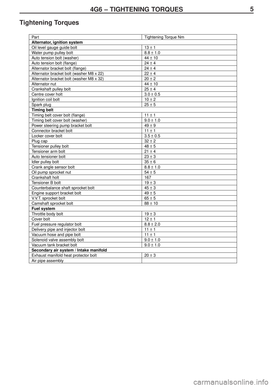
54G6 – TIGHTENING TORQUES
Tightening Torques
Par tTightening Torque Nm
Alternator, ignition system
Oil level gauge guide bolt13 ± 1
Water pump pulley bolt8.8 ± 1.0
Auto tension bolt (washer)44 ± 10
Auto tension bolt (flange)24 ± 4
Alternator bracket bolt (flange)24 ± 4
Alternator bracket bolt (washer M8 x 22)22 ± 4
Alternator bracket bolt (washer M8 x 32)20 ± 2
Alternator nut44 ± 10
Crankshaft pulley bolt25 ± 4
Centre cover holt3.0 ± 0.5
Ignition coil bolt10 ± 2
Spark plug25 ± 5
Timing belt
Timing belt cover bolt (flange)11 ± 1
Timing belt cover bolt (washer)9.0 ± 1.0
Power steering pump bracket bolt49 ± 9
Connector bracket bolt11 ± 1
Locker cover bolt3.5 ± 0.5
Plug cap32 ± 2
Tensioner pulley bolt48 ± 5
Tensioner arm bolt21 ± 4
Auto tensioner bolt23 ± 3
Idler pulley bolt35 ± 6
Crank angle sensor bolt8.8 ± 1.0
Oil pump sprocket nut54 ± 5
Crankshaft holt167
Tensioner B bolt19 ± 3
Counterbalance shaft sprocket bolt45 ± 3
Engine support bracket bolt49 ± 5
V.V.T. sprocket bolt65 ± 5
Camshaft sprocket bolt88 ± 10
Fuel system
Throttle body bolt19 ± 3
Cover bolt12 ± 1
Fuel pressure regulator bolt8.8 ± 2.0
Delivery pipe and injector bolt11 ± 1
Vacuum hose and pipe bolt11 ± 1
Solenoid valve assembly bolt9.0 ± 1.0
Vacuum tank bracket bolt9.0 ± 1.0
Secondary air system / Intake manifold
Exhaust manifold heat protector bolt20 ± 3
Air pipe assembly
Page 120 of 364
134G6 – FUEL SYSTEM
Fuel System
Removal and Installation
Removal Sequence
1. Throttle body assembly
2. Throttle body gasket
3. Cover
4. Gasket
5. Fuel hose
6. Fuel pressure regulator
7. O ring
8. Delivery pipe and injector
9. Insulator
10. Fuel return pipe
11.Insulator
12. Injector
13. O ring14. Grommet
15. Delivery pipe
16. Vacuum hose
17. Vacuum hose
18. Vacuum hose
19. Solenoid valve assembly
20. Solenoid valve assembly
21. Vacuum hose and pipe
22. Solenoid valve assembly
23. Vacuum tank bracket
24. Vacuum tank
25. Vacuum hose assembly
26. Vacuum hose and pipe
�
* 1�*
�
* 1�*
�
* 1�*
�A�*
Page 158 of 364
LAYOUT DIAGRAMS - ENGINE / TRANSMISSION1-8
B-106 (2-grey) Knock sensor
B-108 (2-black) Coolant temperature sensor
B-109 (34-black) ABS-ECU
B-114 (1-black) Water temperature gauge unit
B-115 (3-black) Exhaust cam position sensorB-119 (3-grey) Ignition coil 2
B-122 (3-black) Crank angle sensor
B-123 (3-grey) Ignition coil 1
B-124 (2-black) Fuel pressure solenoid valve
Engine / Transmission (continued)
Connector Symbol
Control harness
Battery harness
Page 159 of 364
LAYOUT DIAGRAMS - ENGINE / TRANSMISSION1-9
B-126 (6-black) Idle speed control servo
B-127 (4) Electric pump relay
B-128 (4) Fuel pump relay 3
B-129 (6-black) Register (for injector)
B-130 (2-black) Fuel pump register
B-131 (3-black) Vehicle speed sensorB-132 (2-black) Back-up lamp switch
B-133 (2-black) Secondary air control solenoid valve
B-134 (2-black) Oil feeder control valve
B-135 (3-black) Manifold absolute pressure sensor
Ground cable
Transmission harness
Page 180 of 364
PART INSTALLATION POSITIONS - SOLENOID VALVES2-10
SOLENOID VALVES
Fuel pump relay 1
Intercooler water
spray relay
Fuel pump relay 2Fuel pump relay 1
Blower relay
Power window relay
Oil feeder control
valveFuel pressure
solenoid valve
Purge control
solenoid valve
Page 188 of 364

3-1
SECTION 3
CIRCUIT DIAGRAMS
CONTENTS
J/B ............................................................3-4
J/C ............................................................3-6
Central Junction....................................3-11
Power Supply ........................................3-18
Starting System ....................................3-23
Ignition ...................................................3-24
Charging ................................................3-26
Engine Control ......................................3-28
Cooling ..................................................3-36
Lighting
Headlights (excl. discharge type).....................3-38
Headlights (discharge type) .............................3-42
Tail lights, position lights, licence plate
lights, lighting monitor report buzzer................3-46
Cabin lights, boot compartment lights,
ignition key cylinder illumination light,
door ajar indicator light ....................................3-50
Fog lamps ........................................................3-54
Headlight levelling system ...............................3-58
Signals
Turn signal lights, hazard warning lights .........3-60
Reversing lights ...............................................3-64
Stop lights ........................................................3-65
Horn .................................................................3-66
Meters
Needle meters..................................................3-68
Remaining fuel warning light, oil pressure
warning light, brake warning light,
seatbelt warning light .......................................3-70
Door Opening / Closing Control
Power windows ................................................3-72
Central door locking
(vehicle without keyless entry) .........................3-78
Central door locking
(vehicle with keyless entry) ..............................3-80
Temperature Control
Heater ..............................................................3-86
Manual air-conditioning ....................................3-90
Fully automatic air-conditioning .......................3-96
Vision / Safety
Windscreen washer / wipers ..........................3-104
Rear washer / wiper .......................................3-108
Demister
(vehicle with heater or manual A/C) ...............3-110
Demister, door mirror heating elements
(vehicle with full auto A/C)..............................3-112
Electric stowable remote control
door mirrors ....................................................3-114
Accessories
Spare audio connectors .................................3-118
Clock ..............................................................3-120
Cigarette lighter, ashtray illumination lamp ....3-121
Cont. on next page
Page 219 of 364
CIRCUIT DIAGRAMS - ENGINE CONTROL SYSTEM3-32
Engine control system (continued)
Ignition
switch (ST)
Starter
relayIdle speed
control
servo
Fuel
pressure
solenoid
valveWaste gate
solenoid
valve 1
Engine ECU
Power steering fluid
pressure switch Engine speed
detection connectorEngine control relay