2005 MITSUBISHI 380 SPEED
[x] Cancel search: SPEEDPage 1016 of 1500

SPECIFICATIONS
ENGINE ELECTRICAL16-39
SERVICE SPECIFICATIONSM1161000300322
ITEMS STANDARD VALUE LIMIT
Alternator
Regulated voltage
(Ambient temperature at voltage
regulator)
20C (4F)14.2 15.4
20C (68F) 13.9 14.9
60C (140F) 13.4 14.5
80C (176F) 13.1 14.5
Alternator output wire voltage drop (at 30 A) VMaximum 0.3
Nominal Output current 110A 70 % of normal output
current
Field coil resistance
Approximately 2 5
Brush protrusion length mm (in)Minimum 2 (0.08)
Starter motor
Free running characteristics Terminal voltage
V11
Current A 95
Speed r/min 2,500 or more
Pinion gap mm (in) 0.5 2.0 (0.02 0.07)
Commutator run-out mm (in) 0.05 (0.002) Minimum 0.1 (0.004)
Commutator diameter mm (in) 29.4 (1.16) Minimum 28.8 (1.13)
Undercut depth mm (in) 0.5 (0.02) Minimum 0.2 (0.008)
Ignition parts
Spark plug gap mm 1.0 1.1
Page 1047 of 1500

WINDSHIELD WIPER AND WASHER
EXTERIOR51-14
WINDSHIELD WIPER AND WASHER
GENERAL DESCRIPTIONM1511000100558
WINDSHIELD WIPER AND WASHER
OPERATION
.
WINDSHIELD LOW-SPEED (AND
HIGH-SPEED) WIPER OPERATION
If the windshield low-speed wiper switch is turned
to the ON position with the ignition switch at the
"ACC" or "ON" position, the column switch sends
a low-speed wiper ON and high-speed wiper OFF
signals to the front-ECU. This turns the wiper sig-
nal on and the wiper speed control relay off
(low-speed), causing the wipers to operate at
low-speed.
If the windshield high-speed wiper switch is
turned to the ON position, the column switch
sends a low-speed wiper OFF and high-speed
wiper ON signals to the front-ECU. This turns
both the wiper signal and the wiper speed control
relay on (high-speed), causing the wipers to
operate at high-speed.
NOTE: The windshield wiper speed is adjustable
with the built-in wiper speed control relay.
High-speed operations take place when the wiper
speed control relay is set to "ON" and low-speed
operations take place when the wiper speed control
relay is set to "OFF".
.
WINDSHIELD INTERMITTENT WIPER
OPERATION
The ETACS-ECU calculates the wiper operation
interval according to the voltage signal sent from the
column switch. Then the ETACS-ECU sends a signal
to the front-ECU. The front-ECU determines the
wiper operation interval and turns on the wiper relay
signal relay. This causes the wiper auto stop relay to
turn on. Then the wiper auto stop relay will turn off
after the wipers reach the park position. This causes
the wiper signal relay and then the wipers to turn off.
If the wiper signal relay remains off for the wiper
operation interval, the relay turns on again, causing
the wipers to operate in intermittent mode.
.
WINDSHIELD MIST WIPER OPERATION
If the windshield mist wiper switch is turned to the
ON position with the ignition switch at the "ACC"
or "ON" position, the mist wiper high-speed oper-
ation signal is sent to the front-ECU. This signal
turns on the wiper speed control relay, causing
the wipers to work at high-speed while the mist
switch is on.
While the windshield mist wiper switch remains
turned on when the intermittent mode is still work-
ing, the wipers work as the mist wiper. However,
the wipers return to the intermittent mode again
when the switch is changed back to "INT" posi-
tion.
To prevent the windshield mist wiper from operat-
ing when the windshield wiper switch is turned
OFF, the windshield mist wiper does not work for
0.5 second after the windshield intermittent wiper
switch, the windshield low-speed wiper switch
and the windshield high-speed wiper switch are
turned OFF.
.
WINDSHIELD WASHER OPERATION
If the windshield washer switch is turned to the
ON position with the ignition switch at "ACC" or
"ON" position, the windshield washer ON signal is
sent to the front-ECU. After 0.3 second, the wind-
shield wiper signal turns on. After the windshield
washer switch signal turns off, the windshield
wiper signal turns off in three seconds.
If the windshield washer switch is turned on while
the windshield wiper is at intermittent mode, and
the windshield washer switch is turned OFF
within 0.2 second, the wiper works only once to
perform mist operation. When the windshield
washer switch is turned on for more than 0.2 sec-
ond, the wiper performs the same movement as
normal condition from the time when 0.2 second
has elapsed, and then returns to intermittent
operation.
WINDSHIELD WIPER AND WASHER DIAGNOSISM1511000700389
The windshield wiper and washer are controlled by
the Simplified Wiring System (SWS). For trouble-
shooting, refer to GROUP 54B, SWS Diagnosis
P.54B-10.NOTE: Even when the ETACS-ECU has failed, the
windshield wiper can work at low speed as fail-safe
mode. (Normally, the windshield wiper operates
when the ignition switch is at the "ACC" position. But,
if it enters the fail-safe mode, the wiper can operate
only when the ignition switch is at the "ON" position.)
Page 1048 of 1500
WINDSHIELD WIPER AND WASHER
EXTERIOR51-15
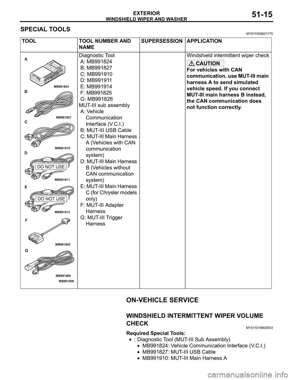
SPECIAL TOOLSM1511000601170
ON-VEHICLE SERVICE
WINDSHIELD INTERMITTENT WIPER VOLUME
CHECK
M1511018900043
Required Special Tools:
: Diagnostic Tool (MUT-III Sub Assembly)
MB991824: Vehicle Communication Interface (V.C.I.)
MB991827: MUT-III USB Cable
MB991910: MUT-III Main Harness A TOOL TOOL NUMBER AND
NAMESUPERSESSION APPLICATION
Diagnostic Tool
A: MB991824
B: MB991827
C: MB991910
D: MB991911
E: MB991914
F: MB991825
G: MB991826
MUT-III sub assembly
A: Vehicle
Communication
Interface (V.C.I.)
B: MUT-III USB Cable
C: MUT-III Main Harness
A (Vehicles with CAN
communication
system)
D: MUT-III Main Harness
B (Vehicles without
CAN communication
system)
E: MUT-III Main Harness
C (for Chrysler models
only)
F: MUT-III Adapter
Harness
G: MUT-III Trigger
HarnessWindshield intermittent wiper check
For vehicles with CAN
communication, use MUT-III main
harness A to send simulated
vehicle speed. If you connect
MUT-III main harness B instead,
the CAN communication does
not function correctly.
Page 1049 of 1500
WINDSHIELD WIPER AND WASHER
EXTERIOR51-16
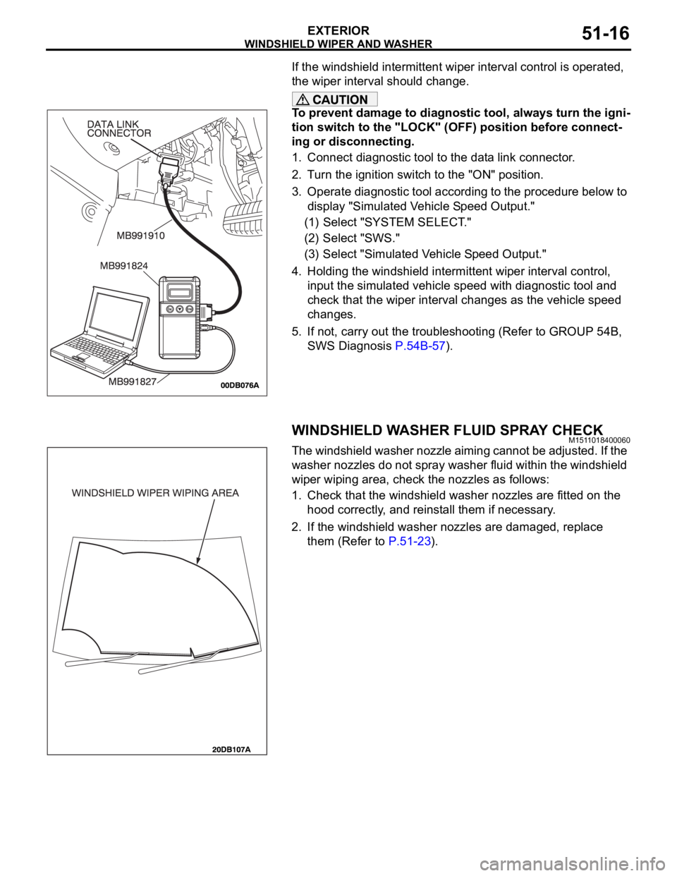
If the windshield intermittent wiper interval control is operated,
the wiper interval should change.
To prevent damage to diagnostic tool, always turn the igni-
tion switch to the "LOCK" (OFF) position before connect-
ing or disconnecting.
1. Connect diagnostic tool to the data link connector.
2. Turn the ignition switch to the "ON" position.
3. Operate diagnostic tool according to the procedure below to
display "Simulated Vehicle Speed Output."
(1) Select "SYSTEM SELECT."
(2) Select "SWS."
(3) Select "Simulated Vehicle Speed Output."
4. Holding the windshield intermittent wiper interval control,
input the simulated vehicle speed with diagnostic tool and
check that the wiper interval changes as the vehicle speed
changes.
5. If not, carry out the troubleshooting (Refer to GROUP 54B,
SWS Diagnosis P.54B-57).
WINDSHIELD WASHER FLUID SPRAY CHECKM1511018400060
The windshield washer nozzle aiming cannot be adjusted. If the
washer nozzles do not spray washer fluid within the windshield
wiper wiping area, check the nozzles as follows:
1. Check that the windshield washer nozzles are fitted on the
hood correctly, and reinstall them if necessary.
2. If the windshield washer nozzles are damaged, replace
them (Refer to P.51-23).
Page 1054 of 1500
WINDSHIELD WIPER AND WASHER
EXTERIOR51-21
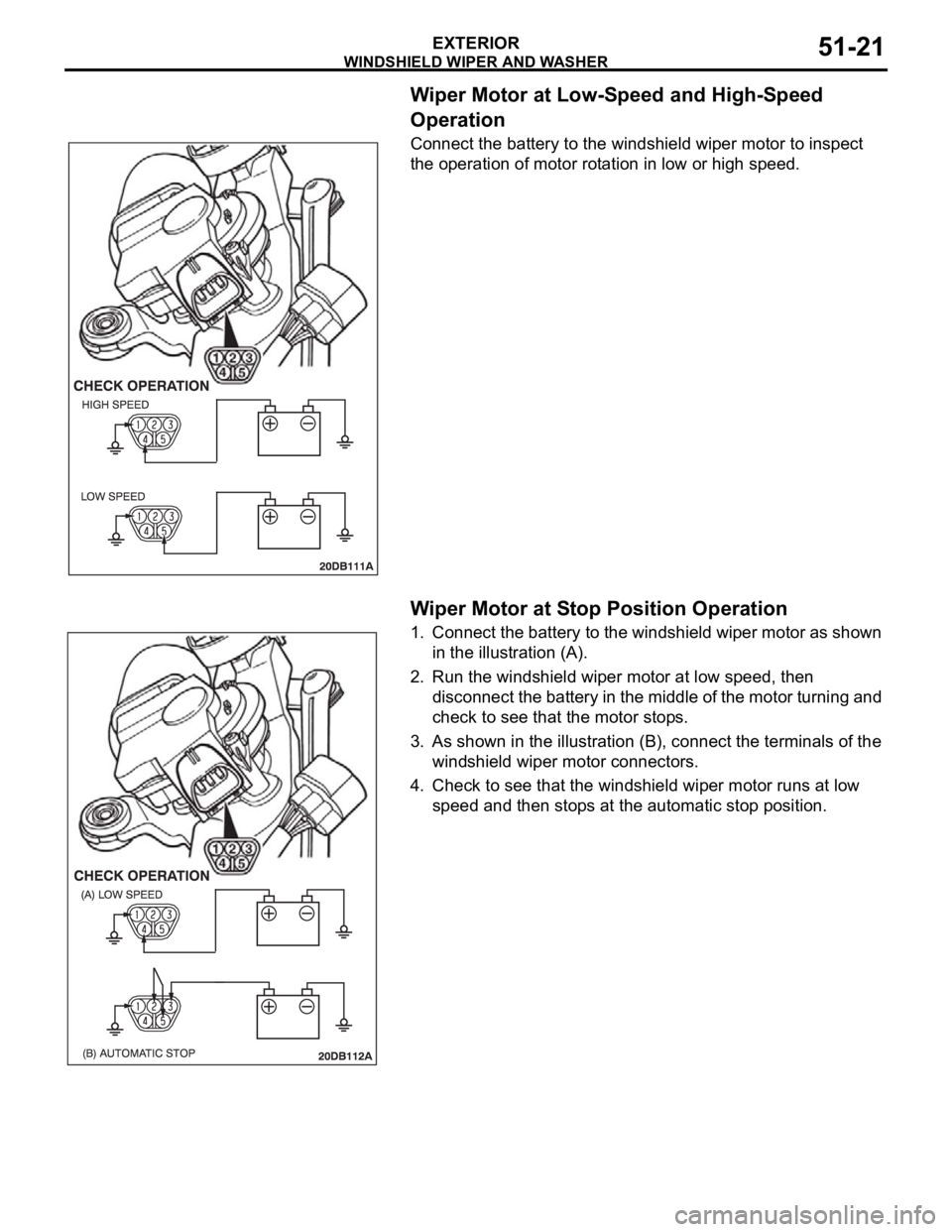
Wiper Motor at Low-Speed and High-Speed
Operation
Connect the battery to the windshield wiper motor to inspect
the operation of motor rotation in low or high speed.
.
Wiper Motor at Stop Position Operation
1. Connect the battery to the windshield wiper motor as shown
in the illustration (A).
2. Run the windshield wiper motor at low speed, then
disconnect the battery in the middle of the motor turning and
check to see that the motor stops.
3. As shown in the illustration (B), connect the terminals of the
windshield wiper motor connectors.
4. Check to see that the windshield wiper motor runs at low
speed and then stops at the automatic stop position.
Page 1055 of 1500
WINDSHIELD WIPER AND WASHER
EXTERIOR51-22
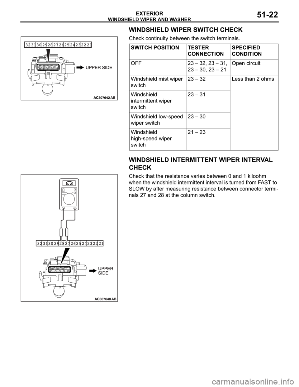
WINDSHIELD WIPER SWITCH CHECK
Check continuity between the switch terminals.
WINDSHIELD INTERMITTENT WIPER INTERVAL
CHECK
Check that the resistance varies between 0 and 1 kiloohm
when the windshield intermittent interval is turned from FAST to
SLOW by after measuring resistance between connector termi-
nals 27 and 28 at the column switch.SWITCH POSITION TESTER
CONNECTIONSPECIFIED
CONDITION
OFF 23
32, 23 31,
23
30, 23 21Open circuit
Windshield mist wiper
switch23
32 Less than 2 ohms
Windshield
intermittent wiper
switch23
31
Windshield low-speed
wiper switch23
30
Windshield
high-speed wiper
switch21
23
Page 1135 of 1500
KEYLESS ENTRY SYSTEM
BODY42-68
If none of the doors is opened or the ignition key
is not inserted in the ignition switch within 30 sec-
onds after the doors are unlocked using the
transmitter, the ETACS-ECU will relock the doors
automatically. This is called "Timer lock function."
This timer lock function prevents accidental
unlocking of doors. The adjustment function
allows you to change the timer lock period from 30 seconds (default setting) to 60, 120 or 180
seconds. For further details on using the
multi-center display (middle grade type) to adjust
the timer lock period, refer to GROUP 54B,
On-vehicle Service P.54B-486.
NOTE: The timer lock period begins when the doors
are unlocked, and ends when the doors is relocked
automatically.
KEYLESS ENTRY SYSTEM DIAGNOSISBGBCJGAI
The keyless entry system is controlled by the Simpli-
fied Wiring System (SWS). Refer to GROUP 54B,
SWS Diagnosis P.54B-57.
SPECIAL TOOLBGBBBGDH
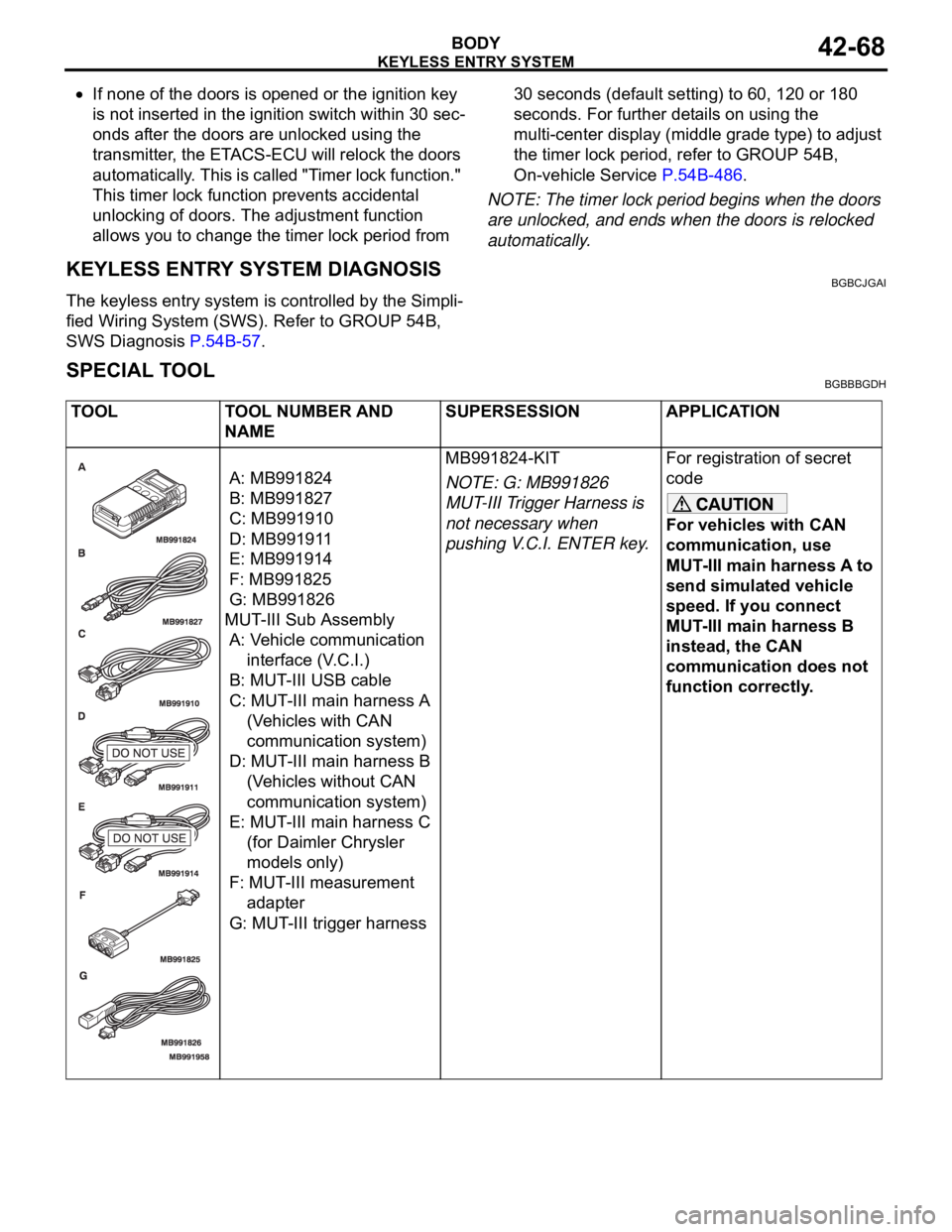
TOOL TOOL NUMBER AND
NAMESUPERSESSION APPLICATION
A: MB991824
B: MB991827
C: MB991910
D: MB991911
E: MB991914
F: MB991825
G: MB991826
MUT-III Sub Assembly
A: Vehicle communication
interface (V.C.I.)
B: MUT-III USB cable
C: MUT-III main harness A
(Vehicles with CAN
communication system)
D: MUT-III main harness B
(Vehicles without CAN
communication system)
E: MUT-III main harness C
(for Daimler Chrysler
models only)
F: MUT-III measurement
adapter
G: MUT-III trigger harnessMB991824-KIT
NOTE: G: MB991826
MUT-III Trigger Harness is
not necessary when
pushing V.C.I. ENTER key.For registration of secret
code
For vehicles with CAN
communication, use
MUT-III main harness A to
send simulated vehicle
speed. If you connect
MUT-III main harness B
instead, the CAN
communication does not
function correctly.
Page 1212 of 1500
ON-VEHICLE SERVICE
PARKING BRAKES36-5
PARKING BRAKE SWITCH CHECKM1361003300411
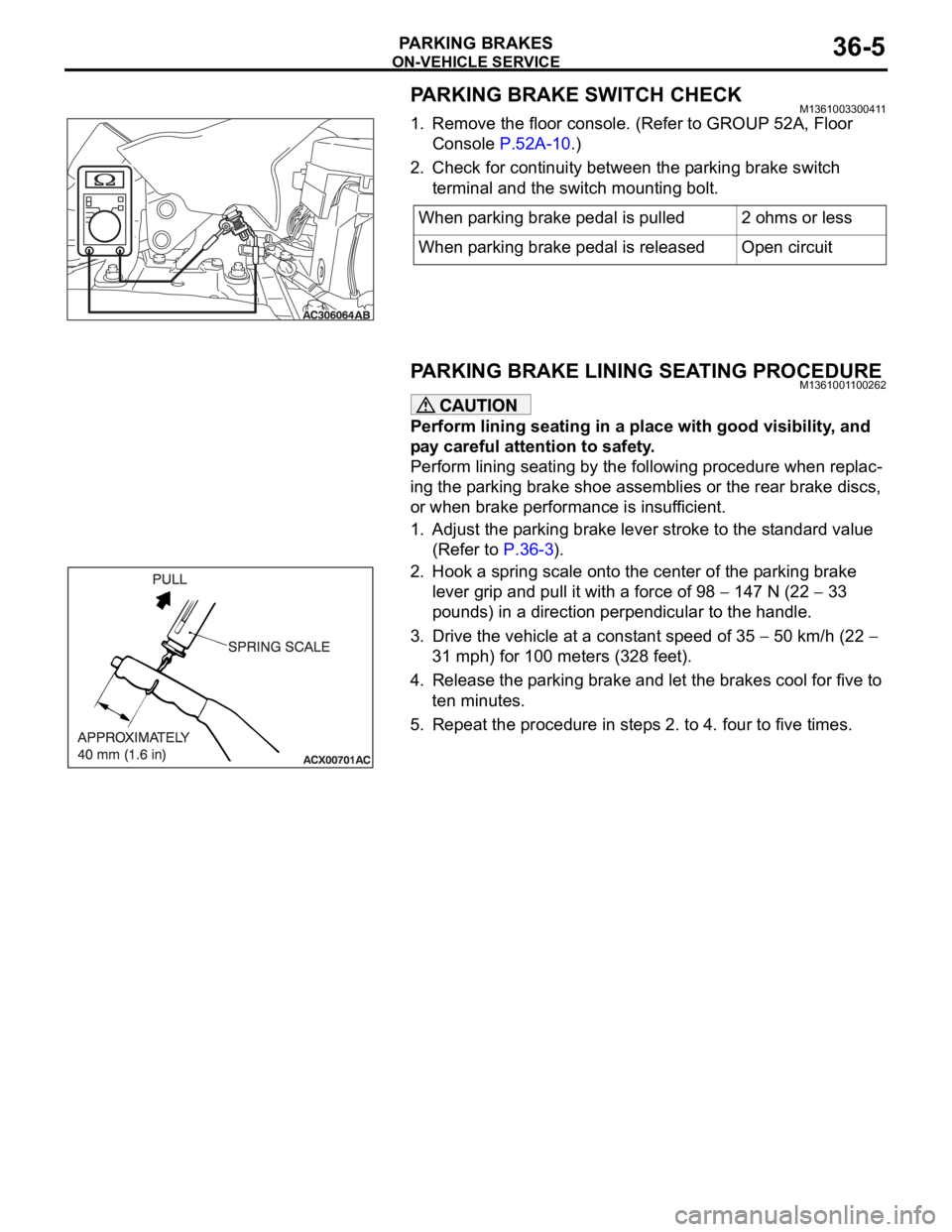
1. Remove the floor console. (Refer to GROUP 52A, Floor
Console P.52A-10.)
2. Check for continuity between the parking brake switch
terminal and the switch mounting bolt.
PARKING BRAKE LINING SEATING PROCEDUREM1361001100262
Perform lining seating in a place with good visibility, and
pay careful attention to safety.
Perform lining seating by the following procedure when replac-
ing the parking brake shoe assemblies or the rear brake discs,
or when brake performance is insufficient.
1. Adjust the parking brake lever stroke to the standard value
(Refer to P.36-3).
2. Hook a spring scale onto the center of the parking brake
lever grip and pull it with a force of 98
147 N (22 33
pounds) in a direction perpendicular to the handle.
3. Drive the vehicle at a constant speed of 35
50 km/h (22
31 mph) for 100 meters (328 feet).
4. Release the parking brake and let the brakes cool for five to
ten minutes.
5. Repeat the procedure in steps 2. to 4. four to five times.When parking brake pedal is pulled 2 ohms or less
When parking brake pedal is released Open circuit