Page 847 of 1500

ON-VEHICLE SERVICE
HEATER, AIR CONDITIONING AND VENTILATION55-146
Sharper bends will reduce the flow of refrigerant. The flexible
hose lines should be routed so that they are at least 80 mm
(3.1 inches) from the exhaust manifold. It is good practice to
inspect all flexible hose lines at least once a year to make sure
they are in good condition and properly routed.
On standard plumbing fittings with O-rings, these O-rings are
not reusable.
AIR CONDITIONING NOISE TEST
You must first know the conditions when the noise occurs.
These conditions are: weather, vehicle speed, in gear or neu-
tral, engine temperature or any other special conditions.
Noises that develop during A/C operation can often be mislead-
ing. For example: what sounds like a failed front bearing or
connecting rod, may be caused by loose bolts, nuts, mounting
brackets, or a loose clutch assembly. Verify accessory drive
belt tension (power steering or generator).
Improper accessory drive belt tension can cause a misleading
noise when the compressor is engaged and little or no noise
when the compressor is disengaged.
Drive belts are speed-sensitive. That is, at different engine
speeds, and depending upon belt tension, belts can develop
unusual noises that are often mistaken for mechanical prob-
lems within the compressor.
Normal air conditioning operation will generate some level of
operational noise. To judge what is normal and abnormal,
requires an understanding of the air conditioning system. This
test is to detail the most common noise complaints and the
repair methods.
VEHICLE CONDITION
1. Ensure the system is not over or under charged.(Refer to
P.55-142).
2. Tighten all compressor mounting bolts, clutch mounting
bolts and compressor drive belt.
3. Inspect layout of the system is correct, ie no interference
between hoses and all retaining clamps are in place.
Page 848 of 1500

ON-VEHICLE SERVICE
HEATER, AIR CONDITIONING AND VENTILATION55-147
TEST PROCEDURES
1. Select a quiet area for testing.
2. Duplicate problem (customer complaint) as much as
possible.
3. Judge if the noise is abnormal (ie. it is important to
understand the characteristics of the vehicle and its normal
state to judge what is abnormal) - Compare with similar
vehicle if necessary.
4. Detail what and how noise occurs.
5. Find the noise source and verify its transmission by isolating
the subject part from the vehicle.
6. Repair the problem.
7. Explain and report your findings.
DETAILS OF A/C NOISE
POSSIBLE CAUSES, CHECKS AND REPAIRS
NOISE DESCRIPTION WHEN IT OCCURS SOURCE OF NOISE
Rumbling (Bearing noise) With A/C On or Off Magnetic clutch, idler pulley
Clang-Clack noise When compressor is engaged Magnetic clutch operation
Squawking (Belt sliding noise) When compressor is engaged V-belt
Whistling or Whooping noise Immediately after the A/C is
engaged.Expansion valve
Hissing or swishing noise When A/C is engaged, but
decreases as flow is stable Refrigerant flow
Rattling (Internal compressor) When compressor is operating Compressor internal part
Wooing (Resonant noise) With A/C On, occurs at certain
speed.Resonance of accessories
Cooing (Discharge pulsation
noise)With A/C On or Off Resonating noise with the vehicle
body
NOISE DESCRIPTION POSSIBLE CAUSE CHECK REPAIR
Rumbling (Bearing
noise)Bearing damage in rotor Manual rotation of bearing Replace compressor
Rotor slipping on boss Wear on compressor boss
surfaceReplace compressor
Bearing damage in pulley Check alignment between
pulleysReplace compressor
Clang-Clack noise Hub to stator misaligned Wear on inner clutch face Replace compressor
Gap between clutch
surface is too largeCheck Air gap is within
specificationReplace compressor
Squawking (Belt sliding
noise)Oil/water between the belt
and rotor surfaceOil and water
contaminationClean
Low belt tension Belt tension Reset or Replace belt and
set tension to correct
specification
Whistling or Whooping
noiseVibration of expansion
valveExpansion valve Replace TX valve
Page 849 of 1500

ON-VEHICLE SERVICE
HEATER, AIR CONDITIONING AND VENTILATION55-148
POWER RELAY CHECKM1552008800321
BLOWER RELAY CONTINUITY CHECK
Hissing or swishing
noiseLow refrigerant quantity Refrigerant level Check system for leaks
and charge to
specification
Rattling (Internal
compressor)Lack of lubricating oil. In a
system with a gas leak
the oil has escaped with
the refrigerantRattling noise from
internal compressorRepalce the compressor
and also fix the system
leak to prevent
reoccurrance
Wooing (Resonant
noise)Drive accessory (P/S
pump, Alternator,etc)
resonating at specific
engine speedThe drive accessories for
vibrationStop vibrations of the
assembly or modify
transmission route to the
vehicle body
Cooing (Discharge
pulsation noise)Pressure fluctuation of
refrigerant discharged
from compressor, which
vibrates the high pressure
pipingRemove the piping
mounting clamps and
re-check. Hold the
condenser without
mountings by hand and
re-checkPut rubber bush between
pipe clamps and the
vehicle body. decrease
refrigerant to minimum
specified level. NOISE DESCRIPTION POSSIBLE CAUSE CHECK REPAIR
BATTERY
VOLTAGETESTER
CONNECTIONSPECIFIED
CONDITION
Not applied 4
5 Open circuit
Connect
terminal 1 to the
positive battery
terminal
Connect
terminal 3 to the
negative battery
terminal4
5 Less than 2 ohms
Page 850 of 1500

ON-VEHICLE SERVICE
HEATER, AIR CONDITIONING AND VENTILATION55-149
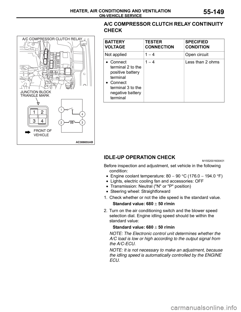
A/C COMPRESSOR CLUTCH RELAY CONTINUITY
CHECK
IDLE-UP OPERATION CHECK
M1552001600401
Before inspection and adjustment, set vehicle in the following
condition:
Engine coolant temperature: 80 90 C (176.0 194.0 F)
Lights, electric cooling fan and accessories: OFF
Transmission: Neutral ("N" or "P" position)
Steering wheel: Straightforward
1. Check whether or not the idle speed is the standard value.
Standard value: 680
50 r/min
2. Turn on the air conditioning switch and the blower speed
selection dial. Engine idling speed should be within the
standard value:
Standard value: 680
50 r/min
NOTE: The Electronic control unit determines whether the
A/C load is low or high according to the output signal from
the A/C-ECU.
NOTE: It is not necessary to make an adjustment, because
the idling speed is automatically controlled by the ENGINE
ECU. BATTERY
V O LTA G ETESTER
CONNECTIONSPECIFIED
CONDITION
Not applied 1
4 Open circuit
Connect
terminal 2 to the
positive battery
terminal
Connect
terminal 3 to the
negative battery
terminal1
4 Less than 2 ohms
Page 879 of 1500

SPECIFICATIONS
HEATER, AIR CONDITIONING AND VENTILATION55-178
SPECIFICATIONS
FASTENER TIGHTENING SPECIFICATIONSM1552012100273
GENERAL SPECIFICATIONSM1552000200262
SERVICE SPECIFICATIONSM1552000300333
LUBRICANTSM1552000400329
ITEM SPECIFICATION
Liquid pipe mounting nut (heater unit side) 4.9
0.9 Nm (43 8 in-lb)
Liquid pipe mounting bolt (condenser side) 4.9
0.9 Nm (44 8 in-lb)
Suction flexible hose mounting nut (compressor side) 25
4 Nm (18 3 ft-lb)
Suction pipe mounting nut (heater unit side) 12
2 Nm (107 17 in-lb)
Suction pipe to suction hose union nut 32
2 Nm
Discharge flexible hose mounting bolt (compressor side) 25
4 Nm (18 3 ft-lb)
Discharge flexible hose mounting nut (condenser side) 12
2 Nm (107 17 in-lb)
ITEM MANUAL AIR CONDITIONING
Heater control Dial type
Air conditioning switch Push-button type
Compressor Type 10S17 (Swashplate type)
Displacement (cm
3)188
Refrigerant Type R134a (HFC-134a)
Amount (grams) 435
475
ITEM STANDARD VALUE
Idle speed r/min 680
50
Idle-up speed r/min 680
50
Air mix damper potentiometer resistance k
1.7 5.0
Air outlet changeover damper potentiometer resistance k
0.8 4.8
Air gap (air conditioning compressor clutch) mm (in) 0.3
0.5 (0.012 0.020)
ITEM SPECIFIED LUBRICANT QUANTITY(ml)
Each connection of refrigerant line ND Oil 8 As required
Compressor refrigerant unit lubricant (ml) ND Oil 8 140
Page 887 of 1500
INSPECTION TERMINAL
COMPONENT LOCATIONS70-8
INSPECTION TERMINALM1701000200354
SENSORM1701000600415
NAME SYMBOL NAME SYMBOL
A/C pressure sensor I Interior temperature sensor
A/C>S
A/T control solenoid valve assembly
(Incorporating transmission fluid
temperature sensor)N Knock sensor C
Accelerator pedal position sensor R Left bank heated oxygen sensor (front)
<3.8L Engine>P
Air thermo sensor T Left bank heated oxygen sensor (rear)
<3.8L Engine>P
Ambient temperature sensor L Manifold absolute pressure sensor B
Camshaft position sensor D Mass airflow sensor G
Crankshaft position sensor A Sunroof assembly (Incorporating pulse
sensor)U
Fuel pump module (Incorporating fuel
level sensor (main) and fuel tank
temperature sensor)W Output shaft speed sensor H
Fuel level sensor (sub) V Photo sensor Q
Right bank heated oxygen sensor
(front) <3.8L Engine>O
Input shaft speed sensor K Right bank heated oxygen sensor (rear)
<3.8L Engine>O
Page 888 of 1500
SENSOR
COMPONENT LOCATIONS70-9
NOTE: The * symbols indicate equipped at both sides.Engine coolant temperature sensor F Throttle body assembly (Incorporating
throttle position sensor)E
Front impact sensor M Wheel speed sensor (front) Y
Side impact sensor a Wheel speed sensor (rear) b NAME SYMBOL NAME SYMBOL
Page 918 of 1500

ENGINE COOLING DIAGNOSIS
ENGINE COOLING14-3
SYMPTOM CHARTM1141005600393
SYMPTOM PROCEDURES
INSPECTION PROCEDURE 1: Coolant Leak
DIAGNOSIS
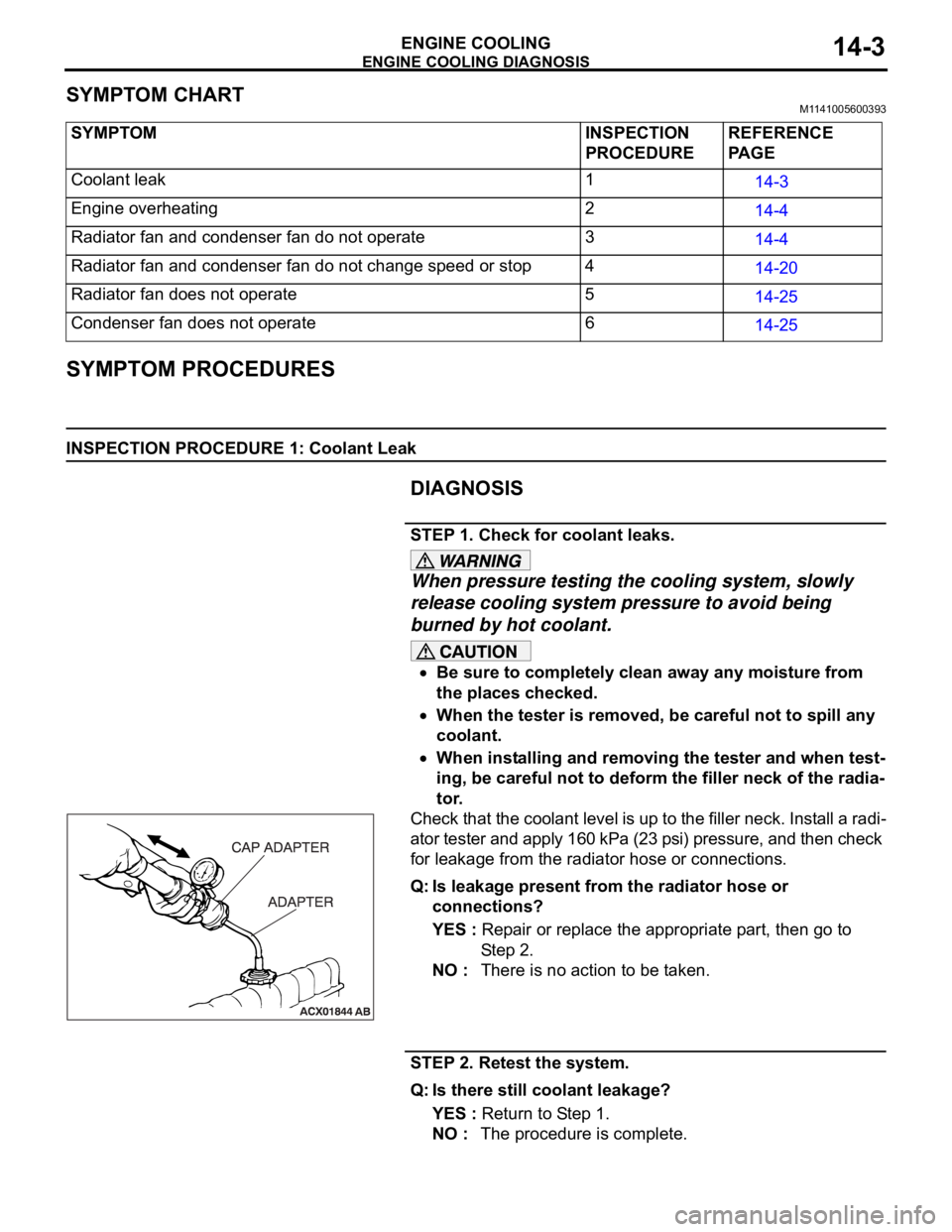
STEP 1. Check for coolant leaks.
When pressure testing the cooling system, slowly
release cooling system pressure to avoid being
burned by hot coolant.
Be sure to completely clean away any moisture from
the places checked.
When the tester is removed, be careful not to spill any
coolant.
When installing and removing the tester and when test-
ing, be careful not to deform the filler neck of the radia-
tor.
Check that the coolant level is up to the filler neck. Install a radi-
ator tester and apply 160 kPa (23 psi) pressure, and then check
for leakage from the radiator hose or connections.
Q: Is leakage present from the radiator hose or
connections?
YES : Repair or replace the appropriate part, then go to
St e p 2 .
NO : There is no action to be taken.
STEP 2. Retest the system.
Q: Is there still coolant leakage?
YES : Return to Step 1.
NO : The procedure is complete. SYMPTOM INSPECTION
PROCEDUREREFERENCE
PA G E
Coolant leak 1
14-3
Engine overheating 2
14-4
Radiator fan and condenser fan do not operate 3
14-4
Radiator fan and condenser fan do not change speed or stop 4
14-20
Radiator fan does not operate 5
14-25
Condenser fan does not operate 6
14-25