2005 MITSUBISHI 380 Ecu
[x] Cancel search: EcuPage 1144 of 1500
SUNROOF ASSEMBLY
BODY42-77
SUNROOF INITIALIZATIONM1426004600123
The sunroof should be initialized when any of the following
components are replaced, the sunroof position is miss timed.
Roof lid glass assembly
Sunroof motor assembly.
1. Ensure the components are correctly assembled. Ensure all
the connectors are connected securely.
2. If the sunroof is already in learn mode, go to step 3. If the
sunroof is not in learn mode, enter learn mode by (1) or (2)
below.
(1) Disconnect the sunroof motor assembly connector while
the sunroof is operating.
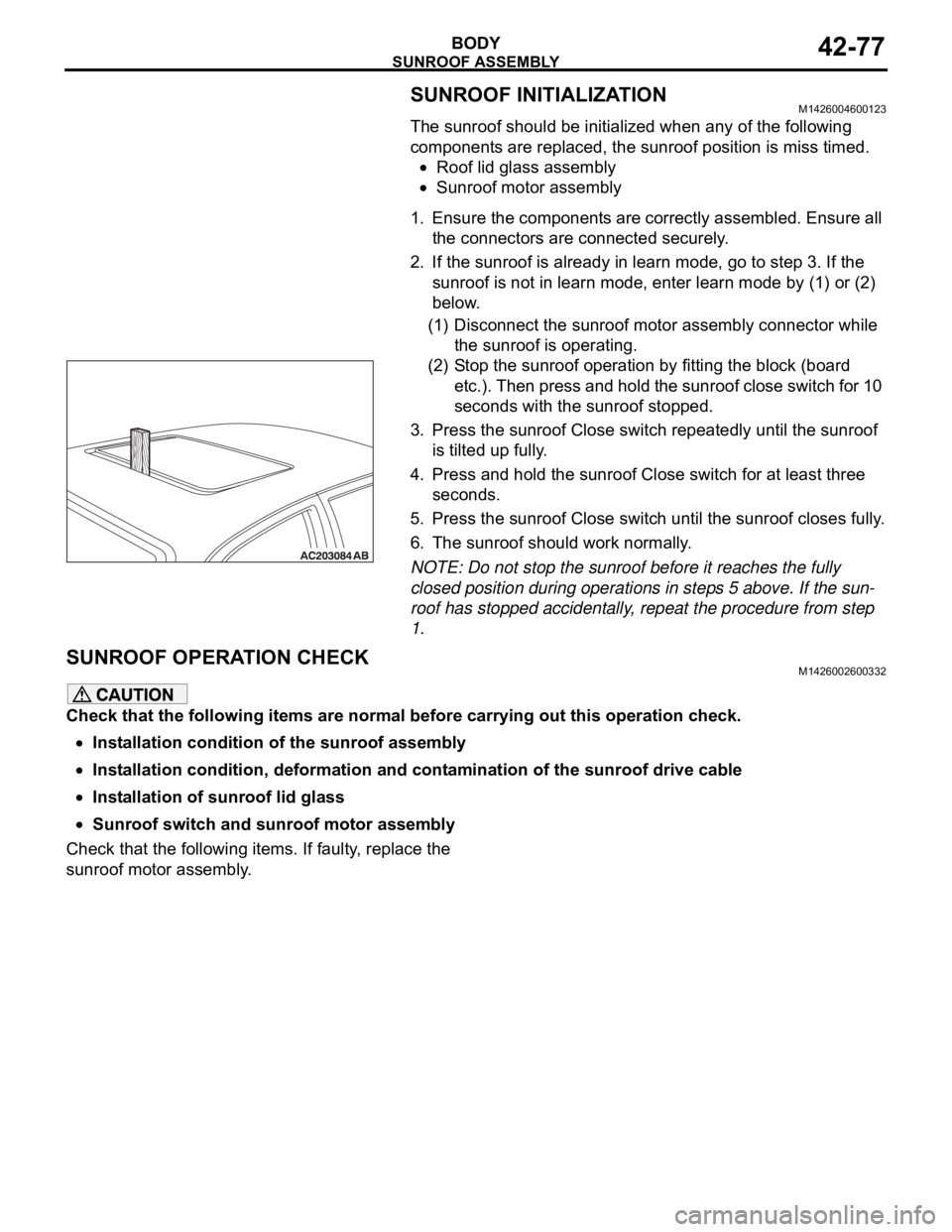
(2) Stop the sunroof operation by fitting the block (board
etc.). Then press and hold the sunroof close switch for 10
seconds with the sunroof stopped.
3. Press the sunroof Close switch repeatedly until the sunroof
is tilted up fully.
4. Press and hold the sunroof Close switch for at least three
seconds.
5. Press the sunroof Close switch until the sunroof closes fully.
6. The sunroof should work normally.
NOTE: Do not stop the sunroof before it reaches the fully
closed position during operations in steps 5 above. If the sun-
roof has stopped accidentally, repeat the procedure from step
1.
SUNROOF OPERATION CHECKM1426002600332
Check that the following items are normal before carrying out this operation check.
Installation condition of the sunroof assembly
Installation condition, deformation and contamination of the sunroof drive cable
Installation of sunroof lid glass
Sunroof switch and sunroof motor assembly
Check that the following items. If faulty, replace the
sunroof motor assembly.
Page 1167 of 1500
GENERAL DESCRIPTION
BASIC BRAKE SYSTEM35A-2
GENERAL DESCRIPTIONM1351000100440
The brake system has been designed to give greater
reliability and durability and to provide excellent brak-
ing performance.
FEATURES
.
Improved braking performance
1. An 8+9 inch tandem brake booster provides suffi-
cient braking force in sudden braking range.
2. 296mm front ventilated disc brakes provide sta-
ble braking force and improved braking feel.
3. 303mm rear ventillated disc brakes are used.
.
Improved stability
1. A 4-wheel anti-lock braking system (4ABS) pre-
vents slipping caused by the vehicle wheels lock-
ing up, in order to maintain a stable vehicle
posture and steering performance.
2. An electronic brake-force distribution (EBD)
makes it possible to maintain the maximum
amount of braking force even when the vehicle's
load is unevenly distributed. 3. Front- and rear-wheel X-type brake line layout
are used.
4. Ventilated discs brakes improve anti-fading per-
formance.
.
Improved serviceability
1. A diagnosis function for the ABS system makes
inspection easier.
2. An outer disc separated hub and rotor make
removal and installation easier.
3. The master cylinder reservoir is utilised for both
brake and clutch fluid on manual transmission
vehicles.
4. The master cylinder filter is coloured black for
improved viewing.
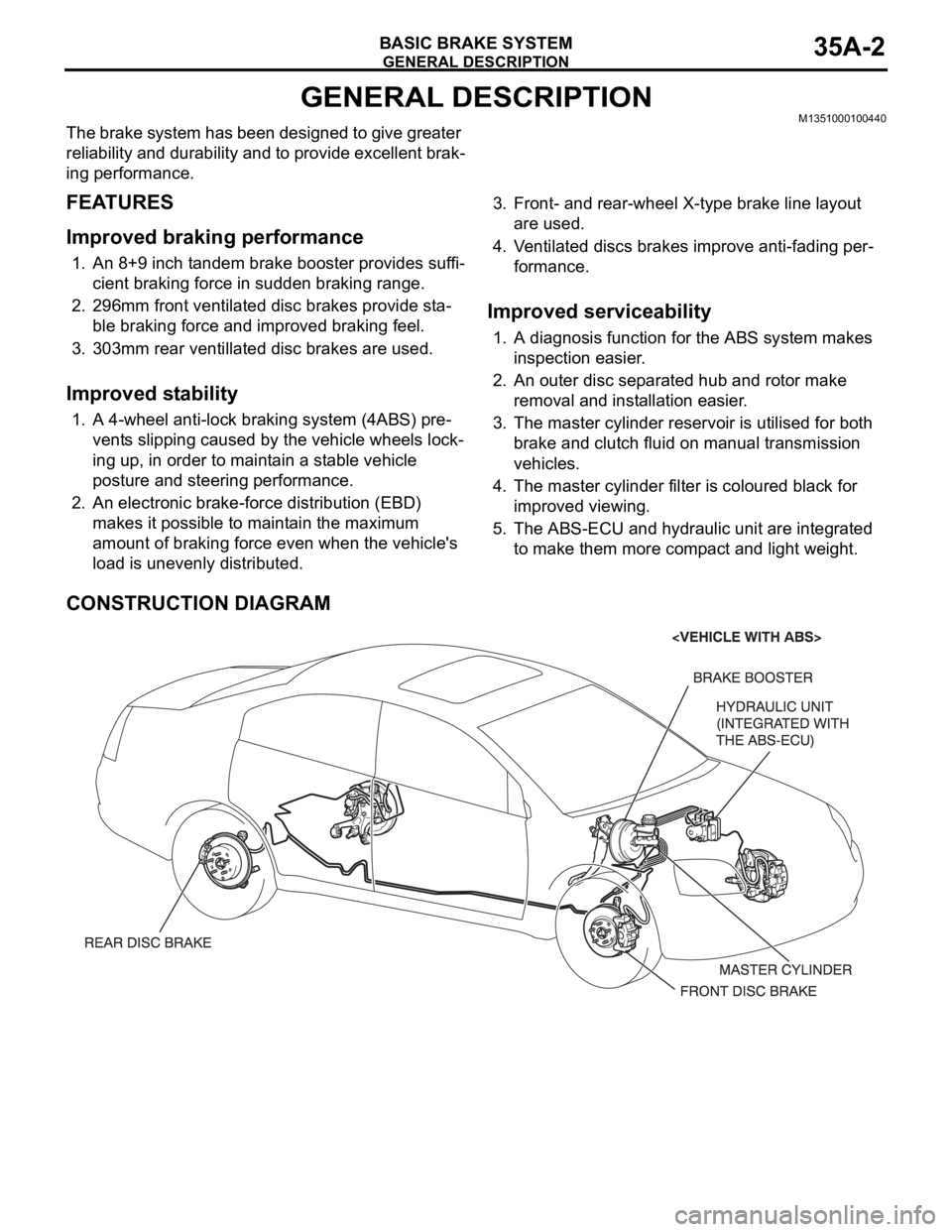
5. The ABS-ECU and hydraulic unit are integrated
to make them more compact and light weight.
CONSTRUCTION DIAGRAM
Page 1183 of 1500
ON-VEHICLE SERVICE
BASIC BRAKE SYSTEM35A-18
Do not wipe off the special grease that is on the lock pin.
Do not contaminate the lock pin.
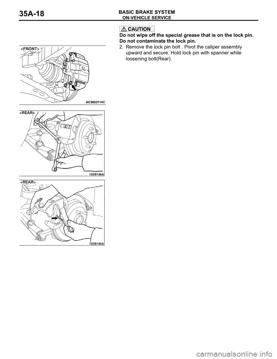
2. Remove the lock pin bolt . Pivot the caliper assembly
upward and secure. Hold lock pin with spanner while
loosening bolt(Rear).
Page 1187 of 1500
ON-VEHICLE SERVICE
BASIC BRAKE SYSTEM35A-22
BRAKE DISC RUN-OUT CHECK AND
CORRECTION
1. Remove the brake assembly, and then hold it with wire.
2. Temporarily install the disc with the hub nut.
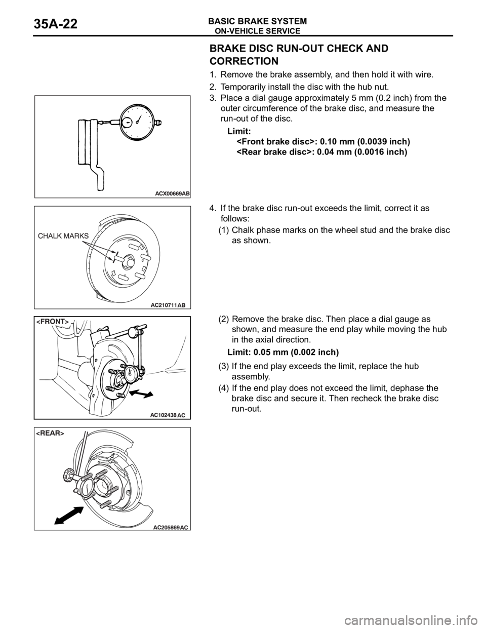
3. Place a dial gauge approximately 5 mm (0.2 inch) from the
outer circumference of the brake disc, and measure the
run-out of the disc.
Limit:
4. If the brake disc run-out exceeds the limit, correct it as
follows:
(1) Chalk phase marks on the wheel stud and the brake disc
as shown.
(2) Remove the brake disc. Then place a dial gauge as
shown, and measure the end play while moving the hub
in the axial direction.
Limit: 0.05 mm (0.002 inch)
(3) If the end play exceeds the limit, replace the hub
assembly.
(4) If the end play does not exceed the limit, dephase the
brake disc and secure it. Then recheck the brake disc
run-out.
Page 1224 of 1500
HOW TO USE THIS MANUAL
GENERAL00-3
HOW TO USE THIS MANUALM1001000100897
MAINTENANCE, REPAIR AND
SERVICING EXPLANATIONS
This manual provides explanations, etc. concerning
procedures for the inspection, maintenance, repair
and servicing of the subject model. Unless otherwise
specified, each service procedure covers all models.
Procedures covering specific models are identified
by the model codes, or similar designation (engine
type, transaxle type, etc). A description of these des-
ignations is covered in this manual under "VEHICLE
IDENTIFICATION."
.
ON-VEHICLE SERVICE
The "ON-VEHICLE SERVICE" section has proce-
dures for performing inspections and adjustments of
particularly important components. These proce-
dures are done with regard to maintenance and ser-
vicing, but other inspections (looseness, play,
cracking, damage, etc.) must also be performed.
.
SERVICE PROCEDURES
The service steps are arranged in numerical order.
Attention to be paid in performing vehicle service are
described in detail in SERVICE POINTS.
DEFINITION OF TERMS
.
STANDARD VALUE
Indicates the value used as the standard for judging
whether or not a part or adjustment is correct.
.
LIMIT
Shows the maximum or minimum value for judging
whether or not a part or adjustment is acceptable.
.
REFERENCE VALUE
Indicates the adjustment value prior to starting the
work (presented in order to facilitate assembly and
adjustment procedures, and so they can be com-
pleted in a shorter time).
.
DANGER, WARNING, AND CAUTION
DANGER, WARNING, and CAUTION call special
attention to a necessary action or to an action that
must be avoided. The differences among DANGER,
WARNING, and CAUTION are as follows:
If a DANGER is not followed, the result is severe
bodily harm or even death.
If a WARNING is not followed, the result could be
bodily injury.
If a CAUTION is not followed, the result could be
damage to the vehicle, vehicle components or
service equipment.
TIGHTENING TORQUE INDICATION
The tightening torque indicates a median and its tol-
erance by a unit of N
m (in-lb.) or Nm (ft.-lb.). For
fasteners with no assigned torque value, refer to
P.00-32.
SPECIAL TOOL NOTE
Only MMC special tool part numbers are called out in
the repair sections of this manual. Please refer to the
special tool cross-reference chart located at the
beginning of each group, for the special tool number
that is available in your market.
ABBREVIATIONS
The following abbreviations are used in this manual
for classification of model types:
A/T:Automatic transaxle, or models equipped with
automatic transaxle.
MPI: Multipoint fuel injection, or engines equipped
with multiport fuel injection.
A/C: Air conditioning.
3.8L engine: 3.8 litre <6G75> engine, or a model
equipped with such an engine.
ABS: Anti-lock Braking System
TCL: Traction Control System
ECU: Electronic Control Unit
V.C.I.: Vehicle Communication Interface
SWS: Simplified Wiring System
CAN: Controller Area Network
M/T: Manual Transmission
SRS: Supplemental Restraint System
Page 1228 of 1500
HOW TO USE TROUBLESHOOTING/INSPECTION SERVICE POINTS
GENERAL00-7
HOW TO USE TROUBLESHOOTING/INSPECTION SERVICE
POINTS
TROUBLESHOOTING CONTENTSM1001013300062
During diagnosis, a DTC code associated with
other system may be set when the ignition
switch is turned on with connector(s) discon-
nected. On completion, confirm all systems
for DTC code(s). If DTC code(s) are set, erase
them all.
When the DIAGNOSTIC TOOL (MUT-III)
detects a diagnostic trouble code, its display
informs users whether a mechanical problem
currently exists (“current trouble”) or whether
it existed before but normal operation has
been restored (“past trouble”). However, if an
MPI, TPMS or SRS airbag-related DTC is set,
“Active DTC/Stored DTC” is not displayed. In
this case, follow the diagnosis procedure for
current trouble.
If a trouble, detected in a CAN communica-
tion-capable system, can be reproduced,
diagnose the CAN bus lines (Refer to GROUP
54C, Can Bus Line Diagnostics Chart
P.54C-15 or P.54C-15).
Troubleshooting of electronic control systems for
which the MUT -III can be used follows the basic out-
line described below. Even in systems for which the
MUT-III cannot be used, part of these systems still
follow this outline.
1. STANDARD FLOW OF DIAGNOSTIC
TROUBLESHOOTING
Troubleshooting strategy is shown in each group.
2. SYSTEM OPERATION AND SYMPTOM
VERIFICATION TESTS
If verification of the symptom(s) is difficult, proce-
dures for checking operation and verifying symptoms
are shown.
3. DIAGNOSTIC FUNCTION
The following trouble code diagnoses are shown.
How to read diagnostic trouble codes
How to erase diagnostic trouble codes
Input inspection service points
4. DIAGNOSTIC TROUBLE CODE CHART
If the MUT-III displays a diagnostic trouble code, find
the applicable inspection procedure according to this
chart.
5. SYMPTOM CHART
If there are symptoms, even though the MUT-III
shows that no DTCs are set, inspection procedures
for each symptom will be found by using this chart.
6. DIAGNOSTIC TROUBLE CODE
PROCEDURES
Indicates the inspection procedures corresponding to
each diagnostic trouble code. (Refer to P.00-9).
7. SYMPTOM PROCEDURES
Indicates the inspection procedures corresponding to
each symptom listed in the Symptom Chart (Refer to
P.00-9).
8. SERVICE DATA REFERENCE TABLE
Inspection items and normal judgment values have
been provided in this chart as reference information.
9. CHECK AT ECU TERMINALS
Terminal numbers for the ECU connectors, inspec-
tion items, and standard values have been provided
in this chart as reference information.
.
TERMINAL VOLTAGE CHECKS
1. Use correct tool to check each pin location on the
ENGINE-ECU Check harnes MB992044 and
measure with voltmeter.
Short-circuiting the positive (+) test probe
between a connector terminal and ground could
damage the vehicle wiring, the sensor, the ECU,
or all three. Use care to prevent this!
2. Insert the correct terminal tool into each of the
ENGINE-ECU check harness connector
terminals, and measure the voltage while referring
to the check chart.
NOTE: Measure voltage with the ECU connectors
connected.
You may find it convenient to pull out the ECU to
make it easier to connect the ENGINE-ECU check
harness.
Page 1229 of 1500

HOW TO USE TROUBLESHOOTING/INSPECTION SERVICE POINTS
GENERAL00-8
Checks don't have to be carried out in the order
given in the chart.
3. If voltage readings differ from normal condition
values, check related sensors, actuators, and
wiring. Replace or repair as needed.
4. After repair or replacement, recheck with the
voltmeter to confirm that the repair has corrected
the problem.
.
TERMINAL RESISTANCE AND
CONTINUITY CHECKS
1. Turn the ignition switch to the “LOCK” (OFF)
position.
2. Disconnect the ECU connector.
If resistance and continuity checks are per-
formed on the wrong terminals, damage to the
vehicle wiring, sensors, ECU, and/or ohmmeter
may occur. Use care to prevent this!
3. Measure the resistance and check for continuity
between the terminals of the ENGIN-ECU check
harness MB992044 connector while referring to
the check chart.
NOTE: Checks don't have to be carried out in the
order given in the chart.
4. If the ohmmeter shows any deviation from the
Normal Condition value, check the corresponding
sensor, actuator and related electrical wiring, then
repair or replace.
5. After repair or replacement, recheck with the
ohmmeter to confirm that the repair has corrected
the problem.
10. INSPECTION PROCEDURES USING
AN OSCILLOSCOPE
When there are inspection procedures using an
oscilloscope, these are listed.
Page 1230 of 1500
HOW TO USE TROUBLESHOOTING/INSPECTION SERVICE POINTS
GENERAL00-9
HOW TO USE THE INSPECTION PROCEDURESM1001013500066
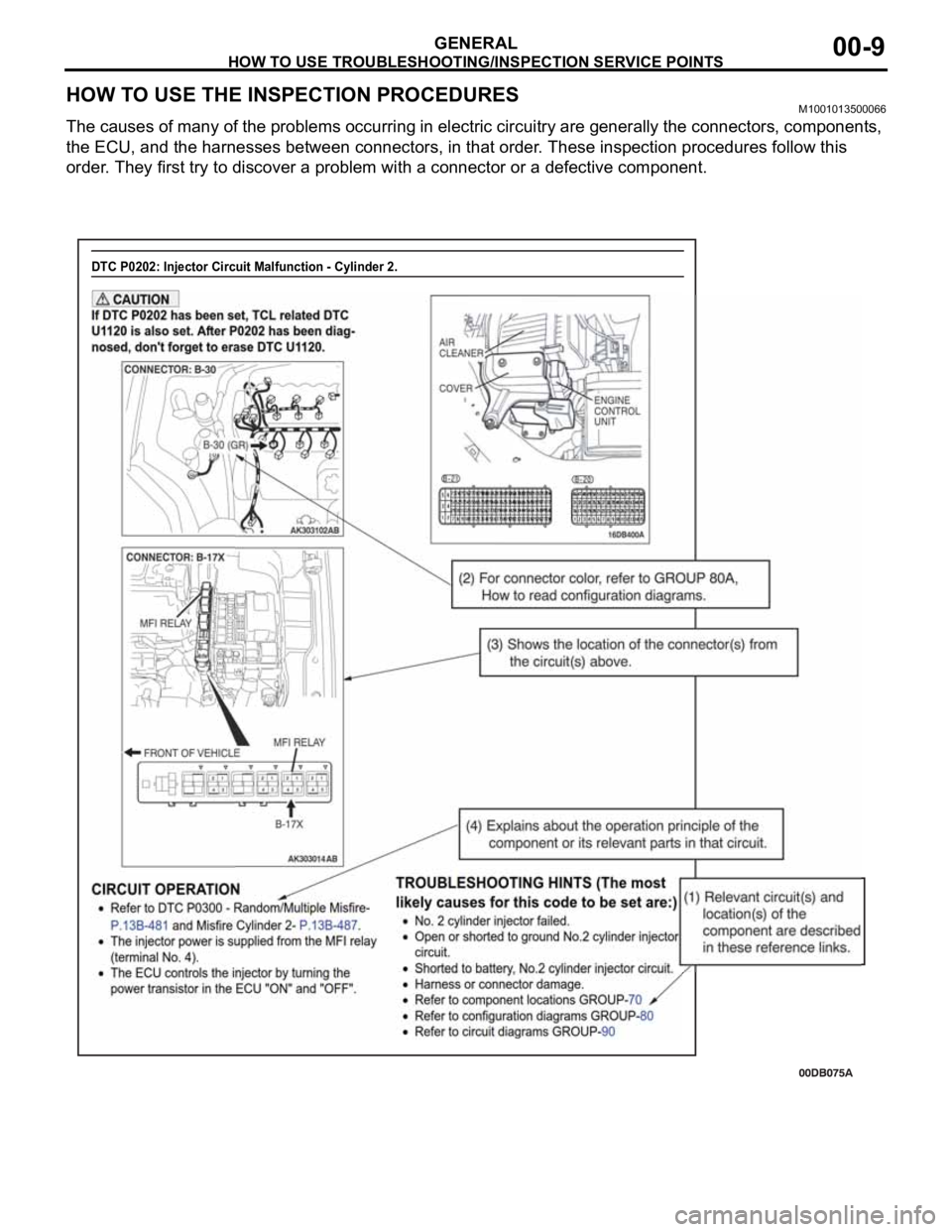
The causes of many of the problems occurring in electric circuitry are generally the connectors, components,
the ECU, and the harnesses between connectors, in that order. These inspection procedures follow this
order. They first try to discover a problem with a connector or a defective component.
DTC P0202: Injector Circuit Malfunction - Cylinder 2.