Page 850 of 1500

ON-VEHICLE SERVICE
HEATER, AIR CONDITIONING AND VENTILATION55-149
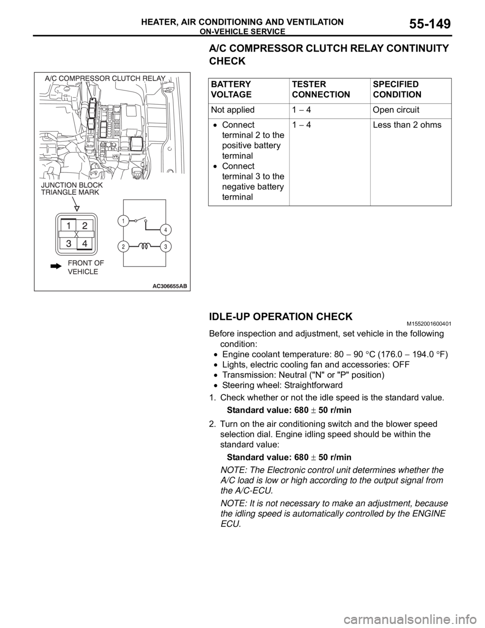
A/C COMPRESSOR CLUTCH RELAY CONTINUITY
CHECK
IDLE-UP OPERATION CHECK
M1552001600401
Before inspection and adjustment, set vehicle in the following
condition:
Engine coolant temperature: 80 90 C (176.0 194.0 F)
Lights, electric cooling fan and accessories: OFF
Transmission: Neutral ("N" or "P" position)
Steering wheel: Straightforward
1. Check whether or not the idle speed is the standard value.
Standard value: 680
50 r/min
2. Turn on the air conditioning switch and the blower speed
selection dial. Engine idling speed should be within the
standard value:
Standard value: 680
50 r/min
NOTE: The Electronic control unit determines whether the
A/C load is low or high according to the output signal from
the A/C-ECU.
NOTE: It is not necessary to make an adjustment, because
the idling speed is automatically controlled by the ENGINE
ECU. BATTERY
V O LTA G ETESTER
CONNECTIONSPECIFIED
CONDITION
Not applied 1
4 Open circuit
Connect
terminal 2 to the
positive battery
terminal
Connect
terminal 3 to the
negative battery
terminal1
4 Less than 2 ohms
Page 851 of 1500
HEATER CONTROL ASSEMBLY AND A/C SWITCH
HEATER, AIR CONDITIONING AND VENTILATION55-150
HEATER CONTROL ASSEMBLY AND A/C SWITCH
REMOVAL AND INSTALLATIONM1552002400369
REMOVAL STEPS
1. CENTER PANEL ASSEMBLY
(REFER TO GROUP 52A,
INSTRUMENT PANEL P.52A-4)
2. HEATER CONTROL (A/C-ECU)
Page 853 of 1500
Page 893 of 1500
CONTROL UNIT
COMPONENT LOCATIONS70-14
CONTROL UNITM1701000700360
NAME SYMBOL NAME SYMBOL
ABS-ECU or ABS/TCL-ECU A Multi center display unit F
A/C-ECU J Engine-ECU B
Column switch (incorporating
column-ECU)D Power window main switch
(incorporating CPU)M
Combination meter (incorporating CPU) E SRS-ECU I
ETACS-ECU G Sunroof assembly (incorporating
sunroof-ECU)K
Front-ECU C A/T-ECU L
Page 904 of 1500

HOW TO DIAGNOSE
GENERAL 00E-3
TROUBLESHOOTING STEPSM1001004400049
If an attempt is made to solve a problem without going through correct steps for troubleshooting, the symp-
toms could become more complicated, resulting in failure to determine the causes correctly and making
incorrect repairs. The four steps below should be followed in troubleshooting.
INFORMATION FOR DIAGNOSISM1001004500132
This manual contains the harness diagrams as well as the individual circuit drawings, operational explana-
tions, and troubleshooting hints for each component. The information is presented in the following manner:
1. Connector diagrams show the connector
positions, etc., on the actual vehicle as well as the
harness path.
2. Circuit diagrams show the configuration of the
circuit with all switches in their normal positions.
3. Operational explanations include circuit drawings
of current flow when the switch is operated and
how the component reacts.4. Troubleshooting hints include numerous
examples of problems which might occur, traced
backward in a common-sense manner to the
origin of the trouble. Problems whose origins may
not be found in this manner are pursued through
the various system circuits.
NOTE: Components of MPI, ETACS, etc. with ECU do not include 3 and 4 above. For this information, refer
to a relevant group which includes details of these components.
Page 906 of 1500
HOW TO DIAGNOSE
GENERAL 00E-5
INSPECTION INSTRUMENTSM1001004700040
For inspection, use the following instruments:
Never use a test light for checking ECU-related circuits or
ECUs.
1. Test light
A test light consists of a 12V bulb and lead wires. It is used
to check voltages or short circuits.
2. Self-powered test light
A self-powered test light consists of a bulb, battery and lead
wires connected in series. It is used to check continuity or
grounding.
Never use a jumper wire to connect a power supply
directly to a load.
3. Jumper wire
A jumper wire is used to close an open circuit.
4. Voltmeter
A voltmeter is used to measure the circuit voltage. Normally,
the positive (red lead) test probe is applied to the point of
voltage measurement and the negative (black lead) test
probe to the body ground. Use a digital voltmeter to check
for voltage drop before or after a component.
Page 910 of 1500

HOW TO DIAGNOSE
GENERAL 00E-9
CABLES AND WIRES CHECKM1001005100041
1. Check connections for looseness, rust, and stains.
2. Check terminals and wires for corrosion.
3. Check terminals and wires for open circuit or impending
open circuit.
4. Check wire insulation and coating for damage, cracks, and
wear.
5. Check conductive parts of terminals for contact with other
metallic parts (vehicle body and other parts).
6. Check grounding parts to verify that there is complete
continuity between attaching bolt(s) and vehicle body.
7. Check for incorrect wiring.
8. Check that harnesses are secured to prevent contact with
sharp edges and corners or hot parts (exhaust manifold,
pipe, etc.).
9. Check that harnesses are secured firmly to provide enough
clearance from the fan pulley, fan belt, and other rotating or
moving parts.
10.Check that the harnesses between fixed parts (such as the
vehicle body) and vibrating parts (such as the engine) are
long enough to allow for vibration and movement.
BATTERY HANDLINGM1001005200048
Battery posts, terminals and related accessories con-
tain lead and lead compounds. WASH HANDS AFTER
HANDLING.
When checking or servicing does not require power from the
vehicle battery, be sure to disconnect the cable from the battery
(
) terminal. This will prevent problems that could be caused by
a short circuit. Disconnect the (
) battery terminal first and
reconnect it last.
GENERAL ELECTRICAL SYSTEM CHECKM1001005300045
A circuit consists of the power supply, switch, relay, load,
ground, etc. There are various methods to check a circuit
including an overall check, voltage check, short-circuit check,
and continuity check. Each of the methods briefly described
below applies only to circuits similar to the illustration.
Page 920 of 1500