Page 1406 of 1500
AUTO-CRUISE CONTROL
ENGINE AND EMISSION CONTROL17-75
AUTO-CRUISE CONTROL
REMOVAL AND INSTALLATIONM1172001400467
Before removal of the air bag module, refer to GROUP 52B, SRS Service Precautions
P.52B-16 and GROUP 52B, Air Bag Module and Clock Spring P.52B-237.
CONTROL SWITCH REMOVAL
STEPS
1. AIR BAG MODULE
SIDE> (REFER TO GROUP 52B, AIR
BAG MODULES AND CLOCK
SPRING P.52B-237)
2. STEERING WHEEL ASSEMBLY
(REFER TO GROUP 37, STEERING
WHEEL P.37-23)
3. LOWER COVER CAP
4. AUTO-CRUISE CONTROL SWITCH
CONTROL UNIT REMOVAL
5. Engine ECU [REFER TO GROUP
13A, Engine ECU 13A-675] SENSOR REMOVAL STEPS
6. TRANSMISSION INHIBITOR
SWITCH (REFER TO GROUP 23B,
AUTOMATIC TRANSMISSION)
7. THROTTLE BODY (BUILT-IN
THROTTLE POSITION SENSOR
AND THROTTLE ACTUATOR
CONTROL MOTOR) (REFER TO
GROUP 13A, THROTTLE BODY
13A-660)
8. ACCELERATOR PEDAL (BUILT-IN
ACCELERATOR PEDAL POSITION
SENSOR) (REFER TO GROUP 17,
ACCELERATOR PEDAL P.17-9)
9. STOPLIGHT SWITCH (REFER TO
GROUP 35A, BRAKE PEDAL
P.35A-24)
Page 1419 of 1500
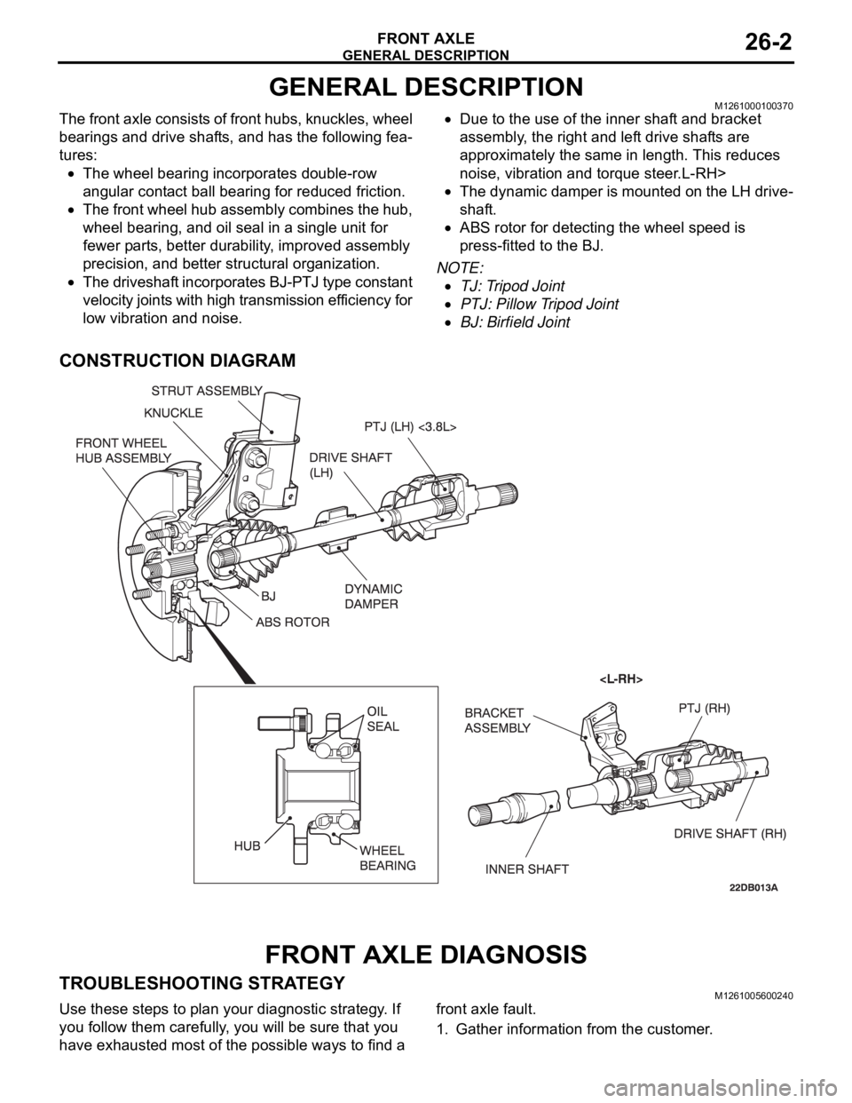
GENERAL DESCRIPTION
FRONT AXLE26-2
GENERAL DESCRIPTIONM1261000100370
The front axle consists of front hubs, knuckles, wheel
bearings and drive shafts, and has the following fea-
tures:
The wheel bearing incorporates double-row
angular contact ball bearing for reduced friction.
The front wheel hub assembly combines the hub,
wheel bearing, and oil seal in a single unit for
fewer parts, better durability, improved assembly
precision, and better structural organization.
The driveshaft incorporates BJ-PTJ type constant
velocity joints with high transmission efficiency for
low vibration and noise.
Due to the use of the inner shaft and bracket
assembly, the right and left drive shafts are
approximately the same in length. This reduces
noise, vibration and torque steer.L-RH>
The dynamic damper is mounted on the LH drive-
shaft.
ABS rotor for detecting the wheel speed is
press-fitted to the BJ.
NOTE: .
TJ: Tripod Joint
PTJ: Pillow Tripod Joint
BJ: Birfield Joint
CONSTRUCTION DIAGRAM
FRONT AXLE DIAGNOSIS
TROUBLESHOOTING STRATEGYM1261005600240
Use these steps to plan your diagnostic strategy. If
you follow them carefully, you will be sure that you
have exhausted most of the possible ways to find a front axle fault.
1. Gather information from the customer.
Page 1430 of 1500
DRIVE SHAFT ASSEMBLY
FRONT AXLE26-13
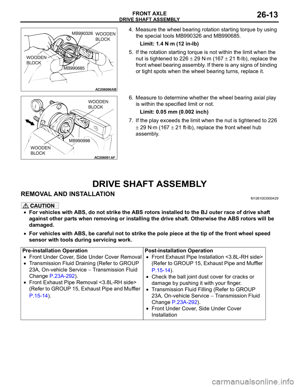
4. Measure the wheel bearing rotation starting torque by using
the special tools MB990326 and MB990685.
Limit: 1.4 N
m (12 in-lb)
5. If the rotation starting torque is not within the limit when the
nut is tightened to 226
29 Nm (167 21 ft-lb), replace the
front wheel bearing assembly. If there is any signs of binding
or tight spots when the wheel bearing turns, replace it.
6. Measure to determine whether the wheel bearing axial play
is within the specified limit or not.
Limit: 0.05 mm (0.002 inch)
7. If the play exceeds the limit when the nut is tightened to 226
29 Nm (167 21 ft-lb), replace the front wheel hub
assembly.
DRIVE SHAFT ASSEMBLY
REMOVAL AND INSTALLATIONM1261003500429
For vehicles with ABS, do not strike the ABS rotors installed to the BJ outer race of drive shaft
against other parts when removing or installing the drive shaft. Otherwise the ABS rotors will be
damaged.
For vehicles with ABS, be careful not to strike the pole piece at the tip of the front wheel speed
sensor with tools during servicing work.
Pre-installation Operation
Front Under Cover, Side Under Cover Removal
Transmission Fluid Draining (Refer to GROUP
23A, On-vehicle Service
Transmission Fluid
Change P.23A-292).
Front Exhaust Pipe Removal <3.8L-RH side>
(Refer to GROUP 15, Exhaust Pipe and Muffler
P.15-14).Post-installation Operation
Front Exhaust Pipe Installation <3.8L-RH side>
(Refer to GROUP 15, Exhaust Pipe and Muffler
P.15-14).
Check the ball joint dust cover for cracks or
damage by pushing it with your finger.
Transmission Fluid Filling (Refer to GROUP
23A, On-vehicle Service
Transmission Fluid
Change P.23A-292).
Front Under Cover, Side Under Cover
Installation
Page 1460 of 1500
23A-1
GROUP 23A
AUTOMATIC
TRANSMISSION
CONTENTS
GENERAL DESCRIPTION. . . . . . . . .23A-3
AUTOMATIC TRANSMISSION
DIAGNOSIS . . . . . . . . . . . . . . . . . . . .23A-12
DIAGNOSTIC TROUBLESHOOTING FLOW23A-12
INTRODUCTION TO A/T DIAGNOSIS . . . . 23A-12
A/T DIAGNOSTIC TROUBLESHOOTING
STRATEGY . . . . . . . . . . . . . . . . . . . . . . . . . 23A-13
DIAGNOSTIC FUNCTION . . . . . . . . . . . . . 23A-13
HOW TO INITIALIZE A/T LEARNING
VALUE . . . . . . . . . . . . . . . . . . . . . . . . . . . . 23A-17
FAIL-SAFE/BACKUP FUNCTION. . . . . . . . 23A-18
ROAD TEST . . . . . . . . . . . . . . . . . . . . . . . . 23A-19
TORQUE CONVERTER STALL TEST . . . . 23A-25
HYDRAULIC PRESSURE TESTS . . . . . . . 23A-26
HYDRAULIC CIRCUIT . . . . . . . . . . . . . . . . 23A-32LINE PRESSURE ADJUSTMENT . . . . . . . . 23A-33
DIAGNOSTIC TROUBLE CODE CHART . . 23A-34
SYMPTOM CHART . . . . . . . . . . . . . . . . . . . 23A-35
DIAGNOSTIC TROUBLE CODE
PROCEDURES . . . . . . . . . . . . . . . . . . . . . . 23A-36
SYMPTOM PROCEDURES . . . . . . . . . . . . 23A-218
DATA LIST REFERENCE TABLE . . . . . . . . 23A-271
ACTUATOR TEST REFERENCE TABLE . . 23A-276
A/T-ECU TERMINAL VOLTAGE REFERENCE
CHART FOR TRANSMISSION OPERATION23A-278
A/T-ECU TERMINAL RESISTANCE AND
CONTINUITY INSPECTION CHART . . . . . 23A-284
INSPECTION PROCEDURE USING AN
OSCILLOSCOPE . . . . . . . . . . . . . . . . . . . . 23A-285
Continued on next page
WARNINGS REGARDING SERVICING OF SUPPLEMENTAL RESTRAINT SYSTEM (SRS) EQUIPPED VEHICLES
Page 1461 of 1500
AUTOMATIC TRANSMISSION23A-2
SPECIAL TOOLS . . . . . . . . . . . . . . . .23A-286
ON-VEHICLE SERVICE. . . . . . . . . . .23A-289
A/T CONTROL COMPONENT LAYOUT . . 23A-289
ESSENTIAL SERVICE . . . . . . . . . . . . . . . . 23A-291
TRANSMISSION FLUID CHECK . . . . . . . . 23A-291
TRANSMISSION FLUID CHANGE . . . . . . . 23A-292
OIL COOLER FLOW CHECK . . . . . . . . . . . 23A-294
TRANSMISSION RANGE SWITCH
CHECK . . . . . . . . . . . . . . . . . . . . . . . . . . . . 23A-294
TRANSMISSION RANGE SWITCH AND
CONTROL CABLE ADJUSTMENT. . . . . . . 23A-294
AUTOMATIC TRANSMISSION CONTROL
COMPONENT CHECK . . . . . . . . . . . . . . . . 23A-295
CRANKSHAFT POSITION SENSOR
CHECK . . . . . . . . . . . . . . . . . . . . . . . . . . . . 23A-295
TRANSMISSION FLUID TEMPERATURE
SENSOR CHECK . . . . . . . . . . . . . . . . . . . . 23A-296
TRANSMISSION RANGE SWITCH
CHECK . . . . . . . . . . . . . . . . . . . . . . . . . . . . 23A-296
STOPLIGHT SWITCH CHECK . . . . . . . . . . 23A-296
A/T CONTROL RELAY CHECK . . . . . . . . . 23A-296
SOLENOID VALVE CHECK . . . . . . . . . . . . 23A-298SELECTOR LEVER OPERATION
CHECK . . . . . . . . . . . . . . . . . . . . . . . . . . . . 23A-299
TRANSMISSION CONTROL CABLE
ADJUSTMENT . . . . . . . . . . . . . . . . . . . . . . 23A-299
TRANSMISSION CONTROL* . . . . . . .23A-300
REMOVAL AND INSTALLATION . . . . . . . . 23A-300
INSPECTION. . . . . . . . . . . . . . . . . . . . . . . . 23A-301
DISASSEMBLY AND ASSEMBLY . . . . . . . 23A-302
INSPECTION. . . . . . . . . . . . . . . . . . . . . . . . 23A-303
TRANSMISSION ASSEMBLY . . . . . .23A-304
REMOVAL AND INSTALLATION . . . . . . . . 23A-304
TRANSMISSION FLUID COOLER,
HOSE AND PIPE . . . . . . . . . . . . . . . .23A-312
REMOVAL AND INSTALLATION . . . . . . . . 23A-312
SPECIFICATIONS . . . . . . . . . . . . . . .23A-313
FASTENER TIGHTENING
SPECIFICATIONS. . . . . . . . . . . . . . . . . . . . 23A-313
SERVICE SPECIFICATIONS . . . . . . . . . . . 23A-313
LUBRICANT . . . . . . . . . . . . . . . . . . . . . . . . 23A-314
Page 1462 of 1500
GENERAL DESCRIPTION
AUTOMATIC TRANSMISSION23A-3
GENERAL DESCRIPTIONM1231000100366
ITEM SPECIFICATION
Transmission modelF5A5A-4-C5Z
Engine model 6G75-S4-MP
Torque converter Type 3-element, 1-stage, 2-phase type
Lock-up Provided
Stall torque ratio 1.71
Transmission type5 forward speeds, 1 reverse speed, fully automatic
Transmission gear
ratio1st 3.789
2nd 2.162
3rd 1.421
4th 1.000
5th 0.686
Reverse 3.117
Final reduction ratio (Differential gear ratio) 3.325
Clutch Multi-disc type 4 sets
Brake Multi-disc type 2 sets, band type 1 set
Manual control system P-R-N-D (4 position) + Sport mode (up, down)
Shift pattern control Electronic control
Hydraulic control during shifting Electronic control (Each clutch hydraulically independently
controlled)
Torque converter clutch control Electronic control
Transmission fluid Specified lubricants MITSUBISHI ELC4-SP III
Quantity (litres) 8.4
Page 1463 of 1500
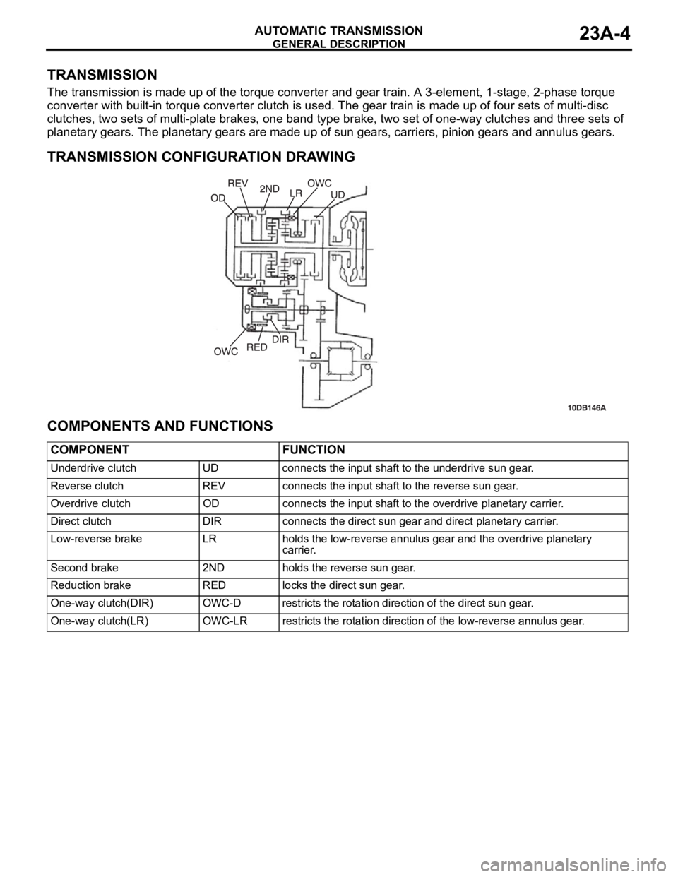
GENERAL DESCRIPTION
AUTOMATIC TRANSMISSION23A-4
TRANSMISSION
The transmission is made up of the torque converter and gear train. A 3-element, 1-stage, 2-phase torque
converter with built-in torque converter clutch is used. The gear train is made up of four sets of multi-disc
clutches, two sets of multi-plate brakes, one band type brake, two set of one-way clutches and three sets of
planetary gears. The planetary gears are made up of sun gears, carriers, pinion gears and annulus gears.
.
TRANSMISSION CONFIGURATION DRAWING
.
COMPONENTS AND FUNCTIONS
COMPONENT FUNCTION
Underdrive clutch UD connects the input shaft to the underdrive sun gear.
Reverse clutch REV connects the input shaft to the reverse sun gear.
Overdrive clutch OD connects the input shaft to the overdrive planetary carrier.
Direct clutch DIR connects the direct sun gear and direct planetary carrier.
Low-reverse brake LR holds the low-reverse annulus gear and the overdrive planetary
carrier.
Second brake 2ND holds the reverse sun gear.
Reduction brake RED locks the direct sun gear.
One-way clutch(DIR) OWC-D restricts the rotation direction of the direct sun gear.
One-way clutch(LR) OWC-LR restricts the rotation direction of the low-reverse annulus gear.
Page 1464 of 1500
GENERAL DESCRIPTION
AUTOMATIC TRANSMISSION23A-5
FUNCTION ELEMENT TABLE
: Function element : Not applicable
NOTE: * operates only when the vehicle is stationary [at approximately 10 km/h (6.2 mph) or less].
OPERATING
ELEMENTSTART PARKING
MECHANI
SMUNDER
DRIVE
CLUTCH
(UD)REVERSE
CLUTCH
(REV)OVER-
DRIVE
CLUTCH
(OD)DIRECT
CLUTCH
(DIR)LOW-
REVERSE
BRAKE
(LR)SECOND
BRAKE
(2ND)REDUCTI-
ON
BRAKE
(RB) TRANSMISSION
RANGE
POK
R
NOK
Sport
mode1st*
2nd
3rd
4th
5th