Page 855 of 1500
HEATER UNIT, HEATER CORE, BLOWER ASSEMBLY AND EVAPORATOR UNIT
HEATER, AIR CONDITIONING AND VENTILATION55-154
DISASSEMBLY AND ASSEMBLYM1551005400365
DISASSEMBLY STEPS
1. PACKING
2. HEATER CORE ASSEMBLY
3. EXPANSION VALVE JOINT
4. EXPANSION VALVE
5. O-RING
6. EVAPORATOR
7. MODE SELECTION DAMPER
CONTROL MOTOR AND
POTENTIOMETER
8. ASPIRATOR
9. ASPIRATOR HOSE
10. AIR THERMO SENSOR CLIP11. AIR THERMO SENSOR
12. FOOT DUCT
13. LEVER A
14. LEVER B
15. LEVER C
16. LEVER D
17. LEVER E
18. HEATER CASE LOWER
19. MODE SELECTION DAMPER
20. MAX A/C DAMPER
21. AIR MIXING DAMPER
22. HEATER CASE UPPERDISASSEMBLY STEPS
Page 856 of 1500

HEATER UNIT, HEATER CORE, BLOWER ASSEMBLY AND EVAPORATOR UNIT
HEATER, AIR CONDITIONING AND VENTILATION55-155
INSPECTIONM1552014301157.
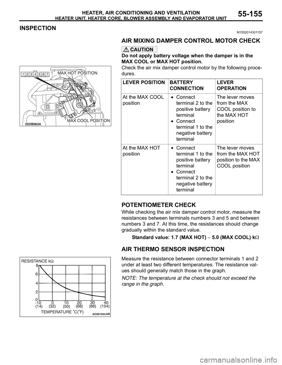
AIR MIXING DAMPER CONTROL MOTOR CHECK
Do not apply battery voltage when the damper is in the
MAX COOL or MAX HOT position.
Check the air mix damper control motor by the following proce-
dures.
.
POTENTIOMETER CHECK
While checking the air mix damper control motor, measure the
resistances between terminals numbers 3 and 5 and between
numbers 3 and 7. At this time, the resistances should change
gradually within the standard value.
Standard value: 1.7 (MAX HOT)
5.0 (MAX COOL) k
AIR THERMO SENSOR INSPECTION
.Measure the resistance between connector terminals 1 and 2
under at least two different temperatures. The resistance val-
ues should generally match those in the graph.
NOTE: The temperature at the check should not exceed the
range in the graph. LEVER POSITION BATTERY
CONNECTIONLEVER
OPERATION
At the MAX COOL
position
Connect
terminal 2 to the
positive battery
terminal
Connect
terminal 1 to the
negative battery
terminalThe lever moves
from the MAX
COOL position to
the MAX HOT
position
At the MAX HOT
position
Connect
terminal 1 to the
positive battery
terminal
Connect
terminal 2 to the
negative battery
terminalThe lever moves
from the MAX HOT
position to the MAX
COOL position
Page 857 of 1500
HEATER UNIT, HEATER CORE, BLOWER ASSEMBLY AND EVAPORATOR UNIT
HEATER, AIR CONDITIONING AND VENTILATION55-156
BLOWER ASSEMBLY DISASSEMBLY AND ASSEMBLYM1551005500209
DISASSEMBLY STEPS
1. OUTSIDE/INSIDE AIR
SELECTION DAMPER CONTROL
MOTOR
2. POWER TRANSISTOR 3. BLOWER MOTOR
4. BLOWER CASE UPPER
5. BLOWER CASE LOWERDISASSEMBLY STEPS
Page 858 of 1500
MOTORS AND TRANSISTOR
HEATER, AIR CONDITIONING AND VENTILATION55-157
MOTORS AND TRANSISTOR
REMOVAL AND INSTALLATIONM1551006900028
MODE SELECTION DAMPER
CONTROL MOTOR REMOVAL
STEP
1. MODE SELECTION DAMPER
CONTROL MOTOR
POWER TRANSISTOR REMOVAL
STEP
GLOVE BOX ASSEMBLY,
INSTRUMENT CENTER PANEL
ASSEMBLY (REFER TO GROUP
52A, INSTRUMENT PANEL
P.52A-4).
2. POWER TRANSISTORBLOWER MOTOR REMOVAL
STEP
3. BLOWER MOTOR
OUTSIDE/INSIDE AIR
SELECTION DAMPER MOTOR
REMOVAL STEP
GLOVE BOX ASSEMBLY,
INSTRUMENT CENTER PANEL
ASSEMBLY (REFER TO GROUP
52A, INSTRUMENT PANEL
P.52A-4).
4. OUTSIDE/INSIDE AIR
SELECTION DAMPER MOTOR
Page 859 of 1500

MOTORS AND TRANSISTOR
HEATER, AIR CONDITIONING AND VENTILATION55-158
INSPECTIONM1551006300338.
MODE SELECTION DAMPER CONTROL MOTOR
CHECK
Do not apply battery voltage when the damper is in the
FACE or DEF position.
Check the mode selection damper control motor by the follow-
ing procedures.
.
POTENTIOMETER CHECK
While checking the mode selection damper control motor, mea-
sure the resistances between terminal numbers 3 and 5 and
between terminal numbers 3 and 7. At this time, the resis-
tances should change gradually within the standard value.
Standard value: 0.8 (DEF)
4.8 (FACE) k
.
OUTSIDE/INSIDE AIR SELECTION DAMPER
CONTROL MOTOR CHECK
Cut off the battery voltage when the damper is in the
inside/outside air position.
Check the outside/inside air selection damper control motor by
the following procedures.LEVER POSITION BATTERY
CONNECTIONLEVER
OPERATION
At the FACE
position
Connect
terminal 2 to the
positive battery
terminal
Connect
terminal 1 to the
negative battery
terminalThe lever moves
from the FACE
position to the DEF
position
At the DEF position
Connect
terminal 1 to the
positive battery
terminal
Connect
terminal 2 to the
negative battery
terminalThe lever moves
from the DEF
position to the
FACE position
Page 860 of 1500
MOTORS AND TRANSISTOR
HEATER, AIR CONDITIONING AND VENTILATION55-159
.
BLOWER FAN AND MOTOR CHECK
When battery voltage is applied between the terminals, check
that the motor operates. Also, check that there is no abnormal
noise.LEVER POSITION BATTERY
CONNECTIONLEVER
OPERATION
At the inside
position
Connect
terminal 1 to the
positive battery
terminal
Connect
terminal 7 to the
negative battery
terminalThe lever moves
from the outside
position to the
inside position
At the outside
position
Connect
terminal 1 to the
positive battery
terminal
Connect
terminal 5 to the
negative battery
terminalThe lever moves
from the inside
position to the
outside position
Page 861 of 1500
SENSORS
HEATER, AIR CONDITIONING AND VENTILATION55-160
SENSORS
REMOVAL AND INSTALLATIONM1554001900088
Required Special Tools:
: Diagnostic Tool (MUT-III Sub Assembly)
MB991824: Vehicle Communication Interface
(V.C.I.)
MB991827: MUT-III USB Cable
MB991910: MUT-III Main Harness A
INTERIOR TEMPERATURE
SENSOR REMOVAL STEPS
LOWER PANEL (REFER TO
GROUP 52A, INSTRUMENT
PA N E L P.52A-4).
1. INTERIOR TEMPERATURE
SENSOR
2. ASPIRATOR HOSEPHOTO SENSOR REMOVAL
STEPS
3. PHOTO SENSOR
Page 862 of 1500
SENSORS
HEATER, AIR CONDITIONING AND VENTILATION55-161
INSPECTIONM1554002000130.
INTERIOR TEMPERATURE SENSOR CHECK
When the resistance between the sensor terminals is mea-
sured under two or more temperature conditions, the resis-
tance should approximately satisfy the illustrated values.
NOTE:
The temperature conditions when checking should not
exceed the range shown in the diagram.
.
PHOTO SENSOR CHECK
1. Connect diagnostic tool , and check the data list of the
photo sensor. (Refer to P.55-133)
2. Check that the displayed value changes when you cover
the photo sensor with your hands.