2005 MITSUBISHI 380 Ignition
[x] Cancel search: IgnitionPage 1014 of 1500
IGNITION SYSTEM
ENGINE ELECTRICAL16-37
INSTALLATION SERVICE POINT
.
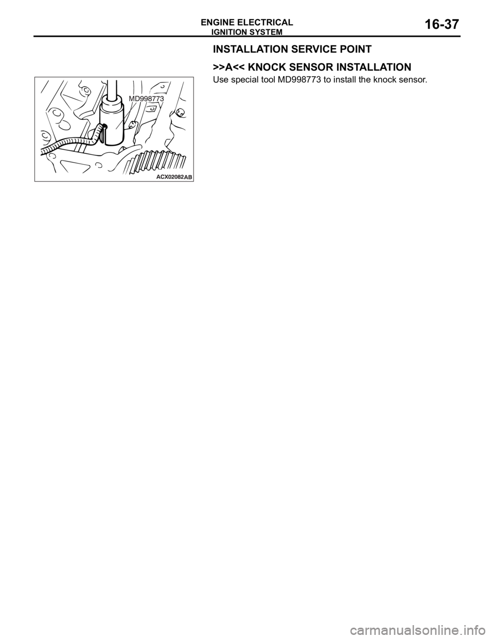
>>A<< KNOCK SENSOR INSTALLATION
Use special tool MD998773 to install the knock sensor.
Page 1015 of 1500

SPECIFICATIONS
ENGINE ELECTRICAL16-38
SPECIFICATIONS
FASTENER TIGHTENING SPECIFICATIONSM1161002100506
GENERAL SPECIFICATIONSM1161000200411
ITEM SPECIFICATION
Charging system
Alternator bracket bolt49
9 Nm (36 7 ft-lb)
Alternator bolt49
9 Nm (36 7 ft-lb)
Alternator terminal nut12
2 Nm (102 22 in-lb)
Ignition system
Camshaft position sensor bolt 11
1 Nm (98 8 in-lb)
Crankshaft position sensor bolt 9.0
1.0 Nm (80 9 in-lb)
Ignition coil bolt 10
2 Nm (89 17 in-lb)
Knock sensor 23
2 Nm (17 1 ft-lb)
Spark plug 25
4 Nm (18 3 ft-lb)
Starting system
Starter bolt 30
3 Nm (23 2 ft-lb)
Starter cover bolt 4.9
1.0 Nm (44 8 in-lb)
Starter terminal nut 12
2 Nm (102 22 in-lb)
ITEMS SPECIFICATIONS
Alternator
Type Positive battery positive voltage sensing
Identification number
Part No. MN180394
Rated output V/A 12/110
Voltage regulator Electronic built-in type
Starter Motor
Type Reduction drive with planetary gear
Identification number M000T31172
Part No. 1810A090
Rated output kW/V 1.2/12
Number of pinion teeth 8
Ignition Coil
Type Molded 6 coil
Spark Plugs
BOSCH FR8DI30
Page 1016 of 1500

SPECIFICATIONS
ENGINE ELECTRICAL16-39
SERVICE SPECIFICATIONSM1161000300322
ITEMS STANDARD VALUE LIMIT
Alternator
Regulated voltage
(Ambient temperature at voltage
regulator)
20C (4F)14.2 15.4
20C (68F) 13.9 14.9
60C (140F) 13.4 14.5
80C (176F) 13.1 14.5
Alternator output wire voltage drop (at 30 A) VMaximum 0.3
Nominal Output current 110A 70 % of normal output
current
Field coil resistance
Approximately 2 5
Brush protrusion length mm (in)Minimum 2 (0.08)
Starter motor
Free running characteristics Terminal voltage
V11
Current A 95
Speed r/min 2,500 or more
Pinion gap mm (in) 0.5 2.0 (0.02 0.07)
Commutator run-out mm (in) 0.05 (0.002) Minimum 0.1 (0.004)
Commutator diameter mm (in) 29.4 (1.16) Minimum 28.8 (1.13)
Undercut depth mm (in) 0.5 (0.02) Minimum 0.2 (0.008)
Ignition parts
Spark plug gap mm 1.0 1.1
Page 1026 of 1500
CROSSMEMBER
POWER PLANT MOUNT32-9
CROSSMEMBER
REMOVAL AND INSTALLATIONM1321003200551
Before removing the steering wheel and air bag module assembly, always refer to GROUP 52B -
Service Precautions (P.52B-16), Air bag Module and Clock Spring (P.52B-237). Also, set the front
wheels so that they are facing straight forward, and remove the ignition key. If you fail to do this,
the SRS clock spring will be damaged, causing the SRS air bag to be inoperative and serious
injury.
*1: Indicates parts which should be initially tightened, and then fully tightened after placing the
vehicle horizontally and loading the full weight of the engine on the vehicle body.
*2: Indicates parts which should be temporarily tightened, and then fully tightened with the vehicle
on the ground in the unladen condition.
Pre-removal Operation
Power Steering Fluid Draining (Refer to GROUP 37,
On-vehicle Service Fluid Replacement P.37-18).
Power Steering Hoses Removal and Installation (Refer to
GROUP 37, Power Steering Hoses P.37A-57).
Air Bag Module and Steering Wheel Assembly Removal
(Refer to GROUP 37, Steering Wheel P.37-23).
Clock Spring Removal (Refer to GROUP 52B, Air Bag
Module and Clock Spring P.52B-237).
Floor Console Assembly Removal (Refer to GROUP 52A,
Floor Console Assembly P.52A-10).
Front Scuff Plate (LH) and Cowl Side Trim (LH) Removal
(Refer to GROUP 52A, Trims P.52A-11).
Trunk Lid Release Handle Cover Removal (Refer to
GROUP 42, Trunk Lid P.42-63).
Accelerator Stopper Removal (Refer to GROUP 17,
Accelerator Pedal P.17-9).
Front Floor Carpet Removal
Centremember Removal (Refer to P.32-7).Post-installation Operation
Centremember Installation (Refer to P.32-7).
Front Floor Carpet Installation
Accelerator Stopper Installation (Refer to GROUP 17,
Accelerator Pedal P.17-9).
Trunk Lid Release Handle Cover Installation (Refer to
GROUP 42, Trunk Lid P.42-63).
Front Scuff Plate (LH) and Cowl Side Trim (LH) Installa-
tion (Refer to GROUP 52A, Trims P.52A-11).
Floor Console Assembly Installation (Refer to GROUP
52A, Floor Console Assembly P.52A-10).
Clock Spring Installation (Refer to GROUP 52B, Air Bag
Module and Clock Spring P.52B-237).
Steering Wheel Assembly and Air Bag Module Installation
(Refer to P.37-23).
Check the dust cover for cracks or damage by pushing it
with your finger.
Power Steering Fluid Supplying (Refer to GROUP 37,
On-vehicle Service Fluid Replacement P.37-18).
Power Steering Fluid Line Bleeding (Refer to P.37-18).
Checking Steering Wheel Position with Wheels Straight
Ahead.
Front Wheel Alignment Adjustment (Refer to GROUP 33,
On-vehicle Service
Front Wheel Alignment Check and
Adjustment P.33-6).
Page 1047 of 1500
WINDSHIELD WIPER AND WASHER
EXTERIOR51-14
WINDSHIELD WIPER AND WASHER
GENERAL DESCRIPTIONM1511000100558
WINDSHIELD WIPER AND WASHER
OPERATION
.
WINDSHIELD LOW-SPEED (AND
HIGH-SPEED) WIPER OPERATION
If the windshield low-speed wiper switch is turned
to the ON position with the ignition switch at the
"ACC" or "ON" position, the column switch sends
a low-speed wiper ON and high-speed wiper OFF
signals to the front-ECU. This turns the wiper sig-
nal on and the wiper speed control relay off
(low-speed), causing the wipers to operate at
low-speed.
If the windshield high-speed wiper switch is
turned to the ON position, the column switch
sends a low-speed wiper OFF and high-speed
wiper ON signals to the front-ECU. This turns
both the wiper signal and the wiper speed control
relay on (high-speed), causing the wipers to
operate at high-speed.
NOTE: The windshield wiper speed is adjustable
with the built-in wiper speed control relay.
High-speed operations take place when the wiper
speed control relay is set to "ON" and low-speed
operations take place when the wiper speed control
relay is set to "OFF".
.
WINDSHIELD INTERMITTENT WIPER
OPERATION
The ETACS-ECU calculates the wiper operation
interval according to the voltage signal sent from the
column switch. Then the ETACS-ECU sends a signal
to the front-ECU. The front-ECU determines the
wiper operation interval and turns on the wiper relay
signal relay. This causes the wiper auto stop relay to
turn on. Then the wiper auto stop relay will turn off
after the wipers reach the park position. This causes
the wiper signal relay and then the wipers to turn off.
If the wiper signal relay remains off for the wiper
operation interval, the relay turns on again, causing
the wipers to operate in intermittent mode.
.
WINDSHIELD MIST WIPER OPERATION
If the windshield mist wiper switch is turned to the
ON position with the ignition switch at the "ACC"
or "ON" position, the mist wiper high-speed oper-
ation signal is sent to the front-ECU. This signal
turns on the wiper speed control relay, causing
the wipers to work at high-speed while the mist
switch is on.
While the windshield mist wiper switch remains
turned on when the intermittent mode is still work-
ing, the wipers work as the mist wiper. However,
the wipers return to the intermittent mode again
when the switch is changed back to "INT" posi-
tion.
To prevent the windshield mist wiper from operat-
ing when the windshield wiper switch is turned
OFF, the windshield mist wiper does not work for
0.5 second after the windshield intermittent wiper
switch, the windshield low-speed wiper switch
and the windshield high-speed wiper switch are
turned OFF.
.
WINDSHIELD WASHER OPERATION
If the windshield washer switch is turned to the
ON position with the ignition switch at "ACC" or
"ON" position, the windshield washer ON signal is
sent to the front-ECU. After 0.3 second, the wind-
shield wiper signal turns on. After the windshield
washer switch signal turns off, the windshield
wiper signal turns off in three seconds.
If the windshield washer switch is turned on while
the windshield wiper is at intermittent mode, and
the windshield washer switch is turned OFF
within 0.2 second, the wiper works only once to
perform mist operation. When the windshield
washer switch is turned on for more than 0.2 sec-
ond, the wiper performs the same movement as
normal condition from the time when 0.2 second
has elapsed, and then returns to intermittent
operation.
WINDSHIELD WIPER AND WASHER DIAGNOSISM1511000700389
The windshield wiper and washer are controlled by
the Simplified Wiring System (SWS). For trouble-
shooting, refer to GROUP 54B, SWS Diagnosis
P.54B-10.NOTE: Even when the ETACS-ECU has failed, the
windshield wiper can work at low speed as fail-safe
mode. (Normally, the windshield wiper operates
when the ignition switch is at the "ACC" position. But,
if it enters the fail-safe mode, the wiper can operate
only when the ignition switch is at the "ON" position.)
Page 1049 of 1500
WINDSHIELD WIPER AND WASHER
EXTERIOR51-16
If the windshield intermittent wiper interval control is operated,
the wiper interval should change.
To prevent damage to diagnostic tool, always turn the igni-
tion switch to the "LOCK" (OFF) position before connect-
ing or disconnecting.
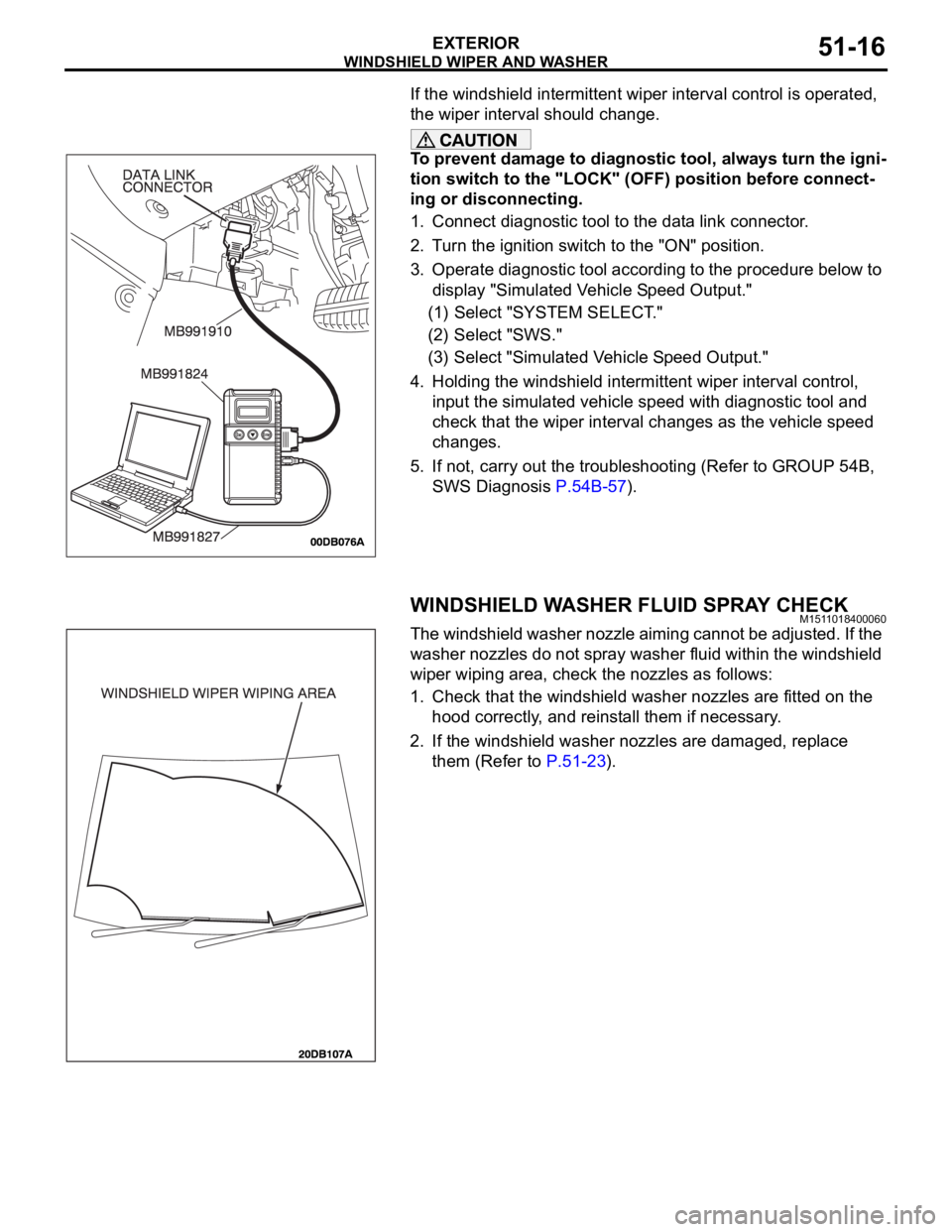
1. Connect diagnostic tool to the data link connector.
2. Turn the ignition switch to the "ON" position.
3. Operate diagnostic tool according to the procedure below to
display "Simulated Vehicle Speed Output."
(1) Select "SYSTEM SELECT."
(2) Select "SWS."
(3) Select "Simulated Vehicle Speed Output."
4. Holding the windshield intermittent wiper interval control,
input the simulated vehicle speed with diagnostic tool and
check that the wiper interval changes as the vehicle speed
changes.
5. If not, carry out the troubleshooting (Refer to GROUP 54B,
SWS Diagnosis P.54B-57).
WINDSHIELD WASHER FLUID SPRAY CHECKM1511018400060
The windshield washer nozzle aiming cannot be adjusted. If the
washer nozzles do not spray washer fluid within the windshield
wiper wiping area, check the nozzles as follows:
1. Check that the windshield washer nozzles are fitted on the
hood correctly, and reinstall them if necessary.
2. If the windshield washer nozzles are damaged, replace
them (Refer to P.51-23).
Page 1060 of 1500

DOOR MIRROR
EXTERIOR51-27
DOOR MIRROR
GENERAL DESCRIPTIONM1511000100570
OPERATION DOOR MIRROR
Remote Controlled Mirror Operation
The mirror on the door mirror moves up/down
and left/right by operating the remote controlled
door mirror switch when the ignition switch is in
the "ON" or "ACC" position.
Page 1090 of 1500
DOOR
BODY42-23
DOOR
GENERAL DESCRIPTIONM1423000100246
OPERATION
.
CENTRAL DOOR LOCKING SYSTEM
The central door locking system operates the door
lock actuator to lock or unlock the doors and the fuel
lid door using the door lock switch built into the front
power window (main or sub) switch or key cylinder
built into the driver's side door outside handle. The
system has the following operations and features:
All doors and fuel lid door can be locked using the
door lock switch built into the front power window
(main or sub
Insert the key into the driver's key cylinder and
turn once to the unlock side to unlock the driver's
door and fuel lid door. Turn the key once again to
the unlock side to unlock all doors and fuel lid
door.
The key reminder function automatically unlocks
all doors when door lock operation is performed
and the front doors are opened while the key is
inserted into the ignition switch.
.
POWER WINDOWS
When the power window (main or sub) switch is
operated, the door windows will open or close. This
system has the following operations and features:
A power window lock switch on the power win-
dow main switch prevents the door window glass
from opening/closing with the front passenger's
and rear power window sub switch.
The power window of the door window glass can
be opened/closed for 30 seconds with the timer
function after the ignition switch is turned OFF.
(The timer expires if the front door
opened when the timer is in operation).
The power window main switch contains a
one-touch down switch that will automatically
open the driver's side door window only.
CENTRAL DOOR LOCKING SYSTEM DIAGNOSISM1427000700217
The central door locking system is controlled by the
simplified wiring system (SWS). Refer to GROUP
54B, SWS Diagnosis P.54B-57.
POWER WINDOW DIAGNOSISM1429000700224
The power window is controlled by the simplified wir-
ing system (SWS). Refer to GROUP 54B, SWS
Diagnosis P.54B-57.
DOOR DIAGNOSIS
INTRODUCTION TO GLASS AND DOOR DIAGNOSISM1423007300241
Glass and door faults include water leaks and
improper opening and closing. Causes for these
faults can include faults in the glass, weatherstrip,
drain hole, waterproof film or door installation.
GLASS AND DOOR DIAGNOSTIC TROUBLESHOOTING STRATEGYM1423006700246
Use these steps to plan your diagnostic strategy. If
you follow them carefully, you will be sure that you
have exhausted most of the possible ways to find a
glass and door fault.
1. Gather information from the customer.2. Verify that the condition described by the
customer exists.
3. Find the malfunction by following the Symptom
Chart.
4. Verify malfunction is eliminated.