Page 907 of 1500

HOW TO DIAGNOSE
GENERAL 00E-6
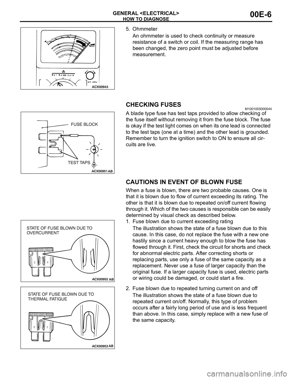
5. Ohmmeter
An ohmmeter is used to check continuity or measure
resistance of a switch or coil. If the measuring range has
been changed, the zero point must be adjusted before
measurement.
CHECKING FUSESM1001005000044
A blade type fuse has test taps provided to allow checking of
the fuse itself without removing it from the fuse block. The fuse
is okay if the test light comes on when its one lead is connected
to the test taps (one at a time) and the other lead is grounded.
Remember to turn the ignition switch to ON to ensure all cir-
cuits are live.
CAUTIONS IN EVENT OF BLOWN FUSE
When a fuse is blown, there are two probable causes. One is
that it is blown due to flow of current exceeding its rating. The
other is that it is blown due to repeated on/off current flowing
through it. Which of the two causes is responsible can be easily
determined by visual check as described below.
1. Fuse blown due to current exceeding rating
The illustration shows the state of a fuse blown due to this
cause. In this case, do not replace the fuse with a new one
hastily since a current heavy enough to blow the fuse has
flowed through it. First, check the circuit for shorts and check
for abnormal electric parts. After correcting shorts or
replacing parts, use only a fuse of the same capacity as a
replacement. Never use a fuse of larger capacity than the
original fuse. If a larger capacity fuse is used, electric parts
or wiring could be damaged, or could start a fire.
2. Fuse blown due to repeated turning current on and off
The illustration shows the state of a fuse blown due to
repeated current on/off. Normally, this type of problem
occurs after a fairly long period of use and is less frequent
than above. In this case, simply replace with a new fuse of
the same capacity.
Page 921 of 1500
ENGINE COOLING DIAGNOSIS
ENGINE COOLING14-6
DIAGNOSIS
STEP 1. Measure the power supply voltage at fan
controller connector A-24.
(1) Disconnect fan controller connector A-24 and measure
wiring harness side connector.
(2) Turn the ignition switch to the "ON" position.
(3) Measure the voltage between fan controller connector A-24
terminal 3 and body earth.
The voltage should measure system voltage.
(4) Turn the ignition switch to the "LOCK" (OFF) position.
(5) Connect fan controller connector A-24.
Q: Is the measured voltage system voltage?
YES : Go to Step 17.
NO : Go to Step 2.
STEP 2. Check the fan controller connector A-24.
Q: Is the connector in good condition?
YES : Go to Step 3.
NO : Repair or replace the connector. Then go to Step 24.
Page 922 of 1500
ENGINE COOLING DIAGNOSIS
ENGINE COOLING14-7
STEP 3. Check the fusible link No.2.
Q: Is the fusible link No.2 in good condition?
YES : Go to Step 4.
NO : Replace the fusible link No.2. Then go to Step 24.
STEP 4. Measure the power supply voltage at fan control
relay connector A-10X.
(1) Disconnect fan control relay connector A-10X (remove the
fan control relay) and measure relay box side connector.
(2) Turn the ignition switch to the "ON" position.
(3) Measure the voltage between fan control relay connector
A-10X terminal 4 and body earth.
The voltage should measure system voltage.
(4) Turn the ignition switch to the "LOCK" (OFF) position.
(5) Connect fan control relay connector A-10X (install the fan
control relay).
Q: Is the measured voltage system voltage?
YES : Go to Step 7.
NO : Go to Step 5.
Page 925 of 1500
ENGINE COOLING DIAGNOSIS
ENGINE COOLING14-10
STEP 10. Measure the terminal voltage at fan control relay
connector A-10X.
(1) Disconnect fan control relay connector A-10X (remove the
fan control relay) and measure relay box side connector.
(2) Turn the ignition switch to the "ON" position.
(3) Measure the voltage between fan control relay connector
A-10X terminal 3 and body earth.
The voltage should measure system voltage.
(4) Turn the ignition switch to the "LOCK" (OFF) position.
(5) Connect fan control relay connector A-10X (install the fan
control relay).
Q: Is the measured voltage system voltage?
YES : Go to Step 13.
NO : Go to Step 11.
Page 934 of 1500

ENGINE COOLING DIAGNOSIS
ENGINE COOLING14-19
STEP 22. Check the fan controller.
(1) Disconnect fan controller connector A-24.
(2) Back out connector terminal pin 2 from connector housing.
(3) Reconnect the connector with connector terminal pin 2 still
removed.
(4) Turn the ignition switch to the "ON" position.
(5) Check for the cooling fan operation.
The cooling fan rotates. (with connector terminal pin 2
disconnected)
(6) Check for the cooling fan operation.
Using a suitable probe connect the fan controller termi-
nal 2 at controller side to earth.The cooling fan stops.
(When pin 2 of fan controller is connected to earth)
(7) Turn the ignition switch to the "OFF" position.
(8) Disconnect fan controller connector A-24, and re-locate
connector terminal pin 2 into connector housing.
(9) Reconnect the connector with connector terminal pin 2
installed correctly.
Q: Does the cooling fan rotate? And when the fan
controller pin 2 is connected to the body earth, does
the cooling fan stop?
YES : Go to Step 23.
NO : Replace the fan motor and fan controller (Refer to
14-25). Then go to Step 24.
Page 939 of 1500

ENGINE COOLING DIAGNOSIS
ENGINE COOLING14-24
STEP 6. Check the fan controller.
(1) Disconnect fan controller connector A-24.
(2) Back out connector terminal pin 2 from connector housing.
(3) Reconnect the connector with connector terminal pin 2 still
removed.
(4) Turn the ignition switch to the "ON" position.
(5) Check for the cooling fan operation.
The cooling fan rotates. (with connector terminal pin 2
disconnected)
(6) Check for the cooling fan operation.
Using a suitable probe connect the fan controller termi-
nal 2 at controller side to earth.The cooling fan stops.
(When pin 2 of fan controller is connected to earth)
(7) Turn the ignition switch to the "OFF" position.
(8) Disconnect fan controller connector A-24, and re-locate
connector terminal pin 2 into connector housing.
(9) Reconnect the connector with connector terminal pin 2
installed correctly.
Q: Does the cooling fan rotate? And when the fan
controller pin 2 is connected to the body earth, does
the cooling fan stop?
YES : Go to Step 7.
NO : Replace the fan motor and fan controller (Refer to
14-25). Then go to Step 8.
Page 944 of 1500

ON-VEHICLE SERVICE
ENGINE COOLING14-29
Do not use alcohol or methanol anti-freeze or any
engine coolants mixed with alcohol or methanol
anti-freeze. The use of an improper anti-freeze can
cause corrosion of the aluminum components.
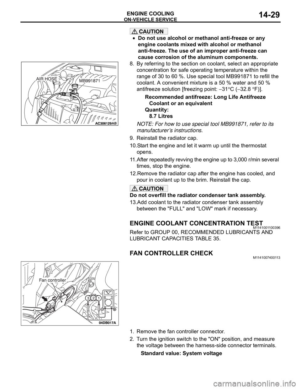
8. By referring to the section on coolant, select an appropriate
concentration for safe operating temperature within the
range of 30 to 60 %. Use special tool MB991871 to refill the
coolant. A convenient mixture is a 50 % water and 50 %
antifreeze solution [freezing point:
31C (32.8 F)].
Recommended antifreeze: Long Life Antifreeze
Coolant or an equivalent
Quantity:
8.7 Litres
NOTE: For how to use special tool MB991871, refer to its
manufacturer’s instructions.
9. Reinstall the radiator cap.
10.Start the engine and let it warm up until the thermostat
opens.
11.After repeatedly revving the engine up to 3,000 r/min several
times, stop the engine.
12.Remove the radiator cap after the engine has cooled, and
pour in coolant up to the brim. Reinstall the cap.
Do not overfill the radiator condenser tank assembly.
13.Add coolant to the radiator condenser tank assembly
between the "FULL" and "LOW" mark if necessary.
ENGINE COOLANT CONCENTRATION TESTM1141001100396
Refer to GROUP 00, RECOMMENDED LUBRICANTS AND
LUBRICANT CAPACITIES TABLE 35.
FAN CONTROLLER CHECKM1141007400113
1. Remove the fan controller connector.
2. Turn the ignition switch to the "ON" position, and measure
the voltage between the harness-side connector terminals.
Standard value: System voltage
Page 978 of 1500

16-1
GROUP 16
ENGINE
ELECTRICAL
CONTENTS
CHARGING SYSTEM . . . . . . . .
16-2
GENERAL DESCRIPTION . . . . . .
16-2
CHARGING SYSTEM DIAGNOSIS16-3
SPECIAL TOOL . . . . . . . . . . . . . . .16-6
ON-VEHICLE SERVICE. . . . . . . . .16-7
ALTERNATOR OUTPUT WIRE VOLTAGE
DROP TEST . . . . . . . . . . . . . . . . . . . . . 16-7
OUTPUT CURRENT TEST . . . . . . . . . . 16-8
REGULATED VOLTAGE TEST . . . . . . . 16-10
WAVE PATTERN CHECK USING AN
OSCILLOSCOPE . . . . . . . . . . . . . . . . . . 16-11
ALTERNATOR ASSEMBLY . . . . .16-14
REMOVAL AND INSTALLATION . . . . . 16-14
DISASSEMBLY AND ASSEMBLY. . . . . 16-15
INSPECTION . . . . . . . . . . . . . . . . . . . . . 16-17
STARTING SYSTEM . . . . . . . . .16-20
GENERAL DESCRIPTION . . . . . .
16-20
STARTING SYSTEM DIAGNOSIS . . . . 16-21
STARTER MOTOR ASSEMBLY . .16-23
REMOVAL AND INSTALLATION . . . . . 16-23
INSPECTION . . . . . . . . . . . . . . . . . . . . . 16-24
DISASSEMBLY AND ASSEMBLY. . . . . 16-26
INSPECTION . . . . . . . . . . . . . . . . . . . . . 16-28
IGNITION SYSTEM . . . . . . . . . . . . . .16-30GENERAL DESCRIPTION . . . . . . .
16-30
SPECIAL TOOLS . . . . . . . . . . . . . .16-30
ON-VEHICLE SERVICE . . . . . . . . .16-31
KNOCK CONTROL SYSTEM CHECK . . 16-31
IGNITION COIL CHECK. . . . . . . . . . . . . 16-31
SPARK PLUG TEST . . . . . . . . . . . . . . . 16-32
SPARK PLUG CHECK AND CLEANING16-32
CAMSHAFT POSITION SENSOR CHECK16-32
CRANKSHAFT POSITION SENSOR
CHECK . . . . . . . . . . . . . . . . . . . . . . . . . . 16-32
IGNITION COIL . . . . . . . . . . . . . . . .16-33
REMOVAL AND INSTALLATION . . . . . 16-33
CAMSHAFT POSITION SENSOR .16-34
REMOVAL AND INSTALLATION . . . . . 16-34
CRANKSHAFT POSITION SENSOR16-35
REMOVAL AND INSTALLATION . . . . . 16-35
KNOCK SENSOR . . . . . . . . . . . . . .16-36
REMOVAL AND INSTALLATION . . . . . 16-36
SPECIFICATIONS . . . . . . . . . . 16-38
FASTENER TIGHTENING
SPECIFICATIONS . . . . . . . . . . . . .
16-38
GENERAL SPECIFICATIONS . . . .16-38
SERVICE SPECIFICATIONS . . . . .16-39