Page 1167 of 1500

GENERAL DESCRIPTION
BASIC BRAKE SYSTEM35A-2
GENERAL DESCRIPTIONM1351000100440
The brake system has been designed to give greater
reliability and durability and to provide excellent brak-
ing performance.
FEATURES
.
Improved braking performance
1. An 8+9 inch tandem brake booster provides suffi-
cient braking force in sudden braking range.
2. 296mm front ventilated disc brakes provide sta-
ble braking force and improved braking feel.
3. 303mm rear ventillated disc brakes are used.
.
Improved stability
1. A 4-wheel anti-lock braking system (4ABS) pre-
vents slipping caused by the vehicle wheels lock-
ing up, in order to maintain a stable vehicle
posture and steering performance.
2. An electronic brake-force distribution (EBD)
makes it possible to maintain the maximum
amount of braking force even when the vehicle's
load is unevenly distributed. 3. Front- and rear-wheel X-type brake line layout
are used.
4. Ventilated discs brakes improve anti-fading per-
formance.
.
Improved serviceability
1. A diagnosis function for the ABS system makes
inspection easier.
2. An outer disc separated hub and rotor make
removal and installation easier.
3. The master cylinder reservoir is utilised for both
brake and clutch fluid on manual transmission
vehicles.
4. The master cylinder filter is coloured black for
improved viewing.
5. The ABS-ECU and hydraulic unit are integrated
to make them more compact and light weight.
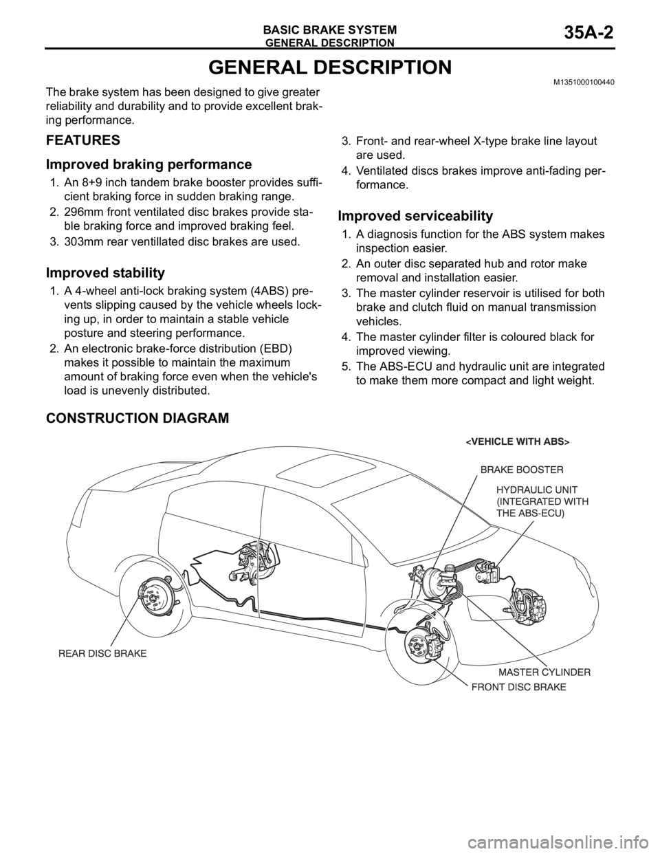
CONSTRUCTION DIAGRAM
Page 1209 of 1500

GENERAL DESCRIPTION
PARKING BRAKES36-2
GENERAL DESCRIPTIONM1361000100344
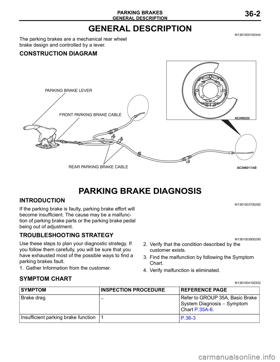
The parking brakes are a mechanical rear wheel
brake design and controlled by a lever.
CONSTRUCTION DIAGRAM
PARKING BRAKE DIAGNOSIS
INTRODUCTIONM1361003700282
If the parking brake is faulty, parking brake effort will
become insufficient. The cause may be a malfunc-
tion of parking brake parts or the parking brake pedal
being out of adjustment.
TROUBLESHOOTING STRATEGYM1361003800290
Use these steps to plan your diagnostic strategy. If
you follow them carefully, you will be sure that you
have exhausted most of the possible ways to find a
parking brakes fault.
1. Gather Information from the customer.2. Verify that the condition described by the
customer exists.
3. Find the malfunction by following the Symptom
Chart.
4. Verify malfunction is eliminated.
SYMPTOM CHARTM1361004100302
SYMPTOM INSPECTION PROCEDURE REFERENCE PAGE
Brake drag
Refer to GROUP 35A, Basic Brake
System Diagnosis
Symptom
Chart P.35A-6.
Insufficient parking brake function 1
P.36-3
Page 1227 of 1500

TROUBLESHOOTING GUIDELINES
GENERAL00-6
TROUBLESHOOTING GUIDELINESM1001008800340
VERIFY THE COMPLAINT
Make sure the customer's complaint and the ser-
vice writer's work order description are under-
stood before starting work.
Make sure you understand the correct operation
of the system. Read the service manual descrip-
tion to verify normal system operation.
Operate the system to see the symptoms. Look
for other symptoms that were not reported by the
customer, or on the work order, that may be
related to the problem.
DETERMINE POSSIBLE CAUSES
Compare the confirmed symptoms to the diagnostic
symptom indexes to find the right diagnosis proce-
dure.
If the confirmed symptoms cannot be found on any
symptom index, determine other possible causes.
Analyze the system diagrams and list all possible
causes for the problem symptoms.
Rank all these possible causes in order of proba-
bility, based on how much of the system they
cover, how likely they are to be the cause, and
how easy they will be to check. Be sure to take
experience into account. Consider the causes of
similar problems seen in the past. The list of
causes should be ranked in order from general to
specific, from most-likely to least-likely, and from
easy-to-check to hard-to-check.
FIND THE PROBLEM
After the symptoms have been confirmed, and prob-
able causes have been identified, the next step is to
make step-by-step checks of the suspected system
components, junctions, and links in logical order.
Use the diagnostic procedures in the service manual
whenever possible. Follow these procedures care-
fully to avoid missing an important step in the diagno-
sis sequence. It might be the skipped step that leads
to the solution of the problem.
If the service manual doesn't have step-by-step pro-
cedures to help diagnose the problem, make a series
of checks based on the ranked list of probable
causes. Troubleshooting checks should be made in
the order that the list of causes was ranked:
general to specific
most-likely to least-likely
easy-to-check to hard-to-check
REPAIR THE PROBLEM
When the step-by-step troubleshooting checks find a
fault, perform the proper repairs. Make sure to fix the
root cause of the problem, not just the symptom. Just
fixing the symptom, without fixing the root cause, will
cause the symptom to eventually return.
VERIFY THE REPAIR
After repairs are made, recheck the operation of the
system to confirm that the problem is eliminated. Be
sure to check the system thoroughly. Sometimes
new problems are revealed after repairs have been
made.
Page 1267 of 1500
![MITSUBISHI 380 2005 Workshop Manual MAINTENANCE SERVICE
GENERAL00-46
NOTE: If it takes some amount of time until the transmission
fluid reaches its normal operating temperature [70
80C
(158
176F)], check the transmission fluid lev MITSUBISHI 380 2005 Workshop Manual MAINTENANCE SERVICE
GENERAL00-46
NOTE: If it takes some amount of time until the transmission
fluid reaches its normal operating temperature [70
80C
(158
176F)], check the transmission fluid lev](/manual-img/19/57086/w960_57086-1266.png)
MAINTENANCE SERVICE
GENERAL00-46
NOTE: If it takes some amount of time until the transmission
fluid reaches its normal operating temperature [70
80C
(158
176F)], check the transmission fluid level by refer-
ring to the left diagram.
2. Park the vehicle on a level surface.
3. Move the selector lever through all positions to fill the torque
converter and the hydraulic circuits with fluid, and then move
the selector lever to the "N" position.
4. After wiping off any dirt around the dipstick, remove the
dipstick and check the condition of the transmission fluid.
NOTE: If the transmission fluid smells as if it is burnt, it
means that the transmission fluid has been contaminated by
fine particles from the bushings and friction materials. Tran-
saxle overhaul and cooler line flushing may be necessary.
5. Check transmission fluid level is at the "HOT" mark on the
dipstick. If the transmission fluid level is less than this, add
DIAMOND ATF SP III until the level reaches the "HOT"
mark.
NOTE: If the transmission fluid level is too low, the oil pump
will draw in air along with the transmission fluid, which will
cause to form bubbles. If the transmission fluid level is too
high, rotating components inside the transaxle will churn the
fluid and air into a foamy liquid. Both conditions (level too
low or too high) will cause the hydraulic pressure to drop,
which will result in late shifting and slipping of the clutches
and brakes.
NOTE: In either case, air bubbles can interfere with normal
valve, clutch, and brake operation. Also, foaming can cause
transmission fluid to escape from the transaxle vent where it
may be mistaken for a leak.
Page 1281 of 1500
GENERAL DESCRIPTION
TRACTION CONTROL SYSTEM (TCL)13C-2
GENERAL DESCRIPTIONM1136000100029
Traction Control systems are a significant safety fea-
ture designed to prevent wheel spin during accelera-
tion. This results in improved vehicle stability and
steer ability. When excessive wheel spin is detected,
the system will automatically reduce engine torque
via the engine management system. The Engine
ECU can reduce throttle position, cut fuel injection
and retard ignition to one or more cylinders depend-ing on how much torque reduction is required and
will continue to occur until the wheels are no longer
spinning. During traction control operation the TCL
warning lamp will flash to inform the driver that the
vehicle is under traction control. This will continue
until traction control is finished.
CONSTRUCTION DIAGRAM
91011
1213141516 12345
678
Page 1333 of 1500

ENGINE AND EMISSION CONTROL17-2
EMISSION CONTROL . . . . . . . .17-76
GENERAL DESCRIPTION . . . . . .
17-76
DIAGNOSIS . . . . . . . . . . . . . . . . . .17-76
SPECIAL TOOLS. . . . . . . . . . . . . .17-76
VACUUM HOSES . . . . . . . . . . . . .17-77
VACUUM HOSE ROUTING. . . . . . . . . . 17-77
VACUUM CIRCUIT DIAGRAM . . . . . . . 17-78
VACUUM HOSE INSTALLATION . . . . . 17-78
VACUUM HOSE CHECK. . . . . . . . . . . . 17-79
POSITIVE CRANKCASE VENTILATION
SYSTEM . . . . . . . . . . . . . . . . . . . . .
17-79
GENERAL DESCRIPTION (POSITIVE
CRANKCASE VENTILATION SYSTEM)17-79
COMPONENT LOCATION . . . . . . . . . . 17-80
POSITIVE CRANKCASE VENTILATION
SYSTEM CHECK. . . . . . . . . . . . . . . . . . 17-80
POSITIVE CRANKCASE VENTILATION
VALVE CHECK . . . . . . . . . . . . . . . . . . . 17-80
EVAPORATIVE EMISSION CONTROL SYSTEM . . . . . . . . . . . . . . . . . . . . .
17-81
GENERAL DESCRIPTION (EVAPORATIVE
EMISSION SYSTEM) . . . . . . . . . . . . . . . 17-81
COMPONENT LOCATION . . . . . . . . . . . 17-82
PURGE CONTROL SYSTEM CHECK
(PURGE FLOW CHECK) . . . . . . . . . . . . 17-82
EVAPORATIVE EMISSION PURGE
SOLENOID CHECK . . . . . . . . . . . . . . . . 17-83
MASS AIRFLOW SENSOR CHECK . . . 17-84
ENGINE COOLANT TEMPERATURE
SENSOR CHECK . . . . . . . . . . . . . . . . . . 17-84
INTAKE AIR TEMPERATURE SENSOR
CHECK. . . . . . . . . . . . . . . . . . . . . .17-84
EVAPORATIVE EMISSION CANISTER
. . . . . . . . . . . . . . . . . . . . . . . . . . . .
17-81
REMOVAL AND INSTALLATION . . . . . . 17-81
INSPECTION . . . . . . . . . . . . . . . . . . . . . 17-81
CATALYTIC CONVERTER . . . . . .17-84
GENERAL DESCRIPTION (CATALYTIC
CONVERTER) . . . . . . . . . . . . . . . . . . . . 17-84
SPECIFICATIONS . . . . . . . . . . 17-85
FASTENER TIGHTENING
SPECIFICATIONS . . . . . . . . . . . . . . . . . 17-85
Page 1334 of 1500
ENGINE CONTROL
ENGINE AND EMISSION CONTROL17-3
ENGINE CONTROL
GENERAL DESCRIPTIONM1171000100437
For the accelerator system, an electronic throttle
actuator control system is utilised, eliminating the
accelerator cable.CONSTRUCTION DIAGRAM
ENGINE CONTROL SYSTEM DIAGNOSIS
INTRODUCTIONM1171002000254
If there is a malfunction in the engine control system,
the accelerator pedal or throttle body may be faulty.
TROUBLESHOOTING STRATEGYM1171002100284
Use these steps to plan your diagnostic strategy.
If you follow them carefully, you will be sure that you
have exhausted most of the possible ways to find an
engine control system fault.
1. Gather information from the customer.2. Verify that the condition described by the
customer exists.
3. Find the malfunction by following the Symptom
Chart.
4. Verify that the malfunction is eliminated.
Page 1335 of 1500
ENGINE CONTROL
ENGINE AND EMISSION CONTROL17-4
SYMPTOM CHARTM1171002200292
SYMPTOM PROCEDURES
INSPECTION PROCEDURE 1: Throttle Valve Will Not Fully Open or Close
.
COMMENT
The throttle body or accelerator pedal position (APP)
sensor is suspected.
.
TROUBLESHOOTING HINTS (THE MOST
LIKELY CAUSES FOR THIS CASE:)
Malfunction of the throttle body.
Malfunction of the accelerator pedal position
(APP) sensor.
Malfunction of the Engine ECU.
Circuit drawings
Refer to circuit diagrams GROUP-90
Refer to configuration diagrams GROUP-80
Refer to component locations GROUP-70 SYMPTOM INSPECTION PROCEDURE REFERENCE PAGE
Throttle Valve Will Not Fully Open or Close 1
P.17-4
Accelerator Pedal Operation Not Smooth (Over
Acceleration)2
P.17-6