Page 1337 of 1500
ENGINE CONTROL
ENGINE AND EMISSION CONTROL17-6
INSPECTION PROCEDURE 2: Accelerator Pedal Operation Not Smooth (Over Acceleration)
.
COMMENT
The accelerator pedal, its installation condition or the
accelerator pedal position (APP) sensor is sus-
pected.
.
TROUBLESHOOTING HINTS (THE MOST
LIKELY CAUSES FOR THIS CASE:)
Malfunction of the accelerator pedal.
Incorrectly installed accelerator pedal.
Malfunction of the accelerator pedal position
(APP) sensor.
Circuit drawings
Refer to circuit diagrams GROUP-90
Refer to configuration diagrams GROUP-80
Refer to component locations GROUP-70
DIAGNOSIS
Required Special Tools:
MB991958: Diagnostic Tool (MUT-III Sub Assembly)
MB991824: V.C.I.
MB991827: MUT-III USB Cable
MB991910: MUT-III Main Harness A
STEP 1. Check if the accelerator pedal is installed
correctly.
Q: Is the accelerator pedal installed correctly?
YES : Go to Step 2.
NO : Replace and reinstall the accelerator pedal. (Refer to
P.17-9). Go to Step 3.
Page 1341 of 1500

AUTO-CRUISE CONTROL
ENGINE AND EMISSION CONTROL17-10
AUTO-CRUISE CONTROL
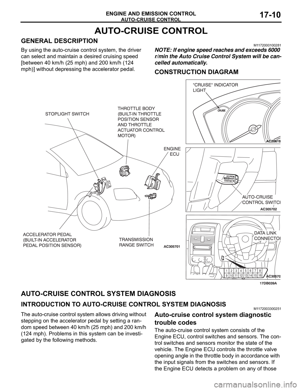
GENERAL DESCRIPTIONM1172000100281
By using the auto-cruise control system, the driver
can select and maintain a desired cruising speed
[between 40 km/h (25 mph) and 200 km/h (124
mph)] without depressing the accelerator pedal.NOTE: If engine speed reaches and exceeds 6000
r/min the Auto Cruise Control System will be can-
celled automatically.
CONSTRUCTION DIAGRAM
AUTO-CRUISE CONTROL SYSTEM DIAGNOSIS
INTRODUCTION TO AUTO-CRUISE CONTROL SYSTEM DIAGNOSISM1172003300251
The auto-cruise control system allows driving without
stepping on the accelerator pedal by setting a ran-
dom speed between 40 km/h (25 mph) and 200 km/h
(124 mph). Problems in this system can be investi-
gated by the following methods.Auto-cruise control system diagnostic
trouble codes
The auto-cruise control system consists of the
Engine ECU, control switches and sensors. The con-
trol switches and sensors monitor the state of the
vehicle. The Engine ECU controls the throttle valve
opening angle in the throttle body in accordance with
the input signals from the switches and sensors. If
the Engine ECU detects a problem on any of those
91
01
1
12
1
31
41
5
16 123
456
78
Page 1346 of 1500

AUTO-CRUISE CONTROL
ENGINE AND EMISSION CONTROL17-15
DIAGNOSTIC TROUBLE CODE PROCEDURES
DTC P0830: Clutch Switch (5M/T Only)
.
CIRCUIT OPERATION
A 5 Volt power supply is applied to the clutch
switch output terminal (terminal No. 1) from the
ENGINE-ECU(terminal No. B-21 pin 41) when
the clutch pedal is applied the power supply is
switched to earth.
.
TECHNICAL DESCRIPTION
The ENGINE-ECU uses the clutch switch earth-
ing as a signal that clutch pedal has been
applied.
.
DTC SET CONDITIONS
Check Conditions
Vehicle speed is above 50 km/h.Judgement Criteria
Gear shift is above 5 times.
Clutch control is below 2 times.
No MIL.
No Limp home.
.
TROUBLESHOOTING HINTS (The most
likely causes for this code to be set are:)
Clutch switch failed
Harness damage in clutch switch circuit, or con-
nector damage.
Refer to component locations GROUP-70
Refer to configuration diagrams GROUP-80
Refer to circuit diagrams GROUP-90
DIAGNOSIS
Required Special Tools:
: Diagnostic tool (MUT-III Sub Assembly)
MB991824: V.C.I.
MB991827: USB Cable
MB991910: Main Harness A
Page 1352 of 1500

AUTO-CRUISE CONTROL
ENGINE AND EMISSION CONTROL17-21
CIRCUIT OPERATION
This circuit judges the signals of each switch
("COAST/SET", "ACC/RES" and "CANCEL") of the
auto-cruise control switch. The Engine ECU detects
the state of the auto-cruise control switch by sensing
the voltages shown below.
When all switches are OFF: 4.7 5.0 volts
When the "CRUISE" (MAIN) switch is "ON": 0
0.3 volt
When the "COAST/SET" switch is ON: 2.0 2.8
volts
When the "ACC/RES" switch is ON: 3.3 4.1
volts
When the "CANCEL" switch is ON: 0.8 1.5 volts
.
DTC SET CONDITIONS
Check Condition
The "CRUISE" indicator lamp illuminates.Judgement Criteria
If the auto-cruise control switch is operated, this
DTC will be set when the Engine ECU terminal
voltage is different from the standard value.
.
TROUBLESHOOTING HINTS (THE MOST
LIKELY CAUSES FOR THIS CASE:)
Malfunction of the auto-cruise control switch.
Malfunction of the clock spring.
Damaged harness or connector.
Malfunction of the Engine ECU.
Circuit drawings
Refer to circuit diagrams GROUP-90
Refer to configuration diagrams GROUP-80
Refer to component locations GROUP-70
DIAGNOSIS
Required Special Tools:
MB991958: Diagnostic Tool (MUT-III Sub Assembly)
MB991824: V.C.I.
MB991827: MUT-III USB Cable
MB991910: MUT-III Main Harness A
MB991223: Harness Set
MB992044: ENGINE-ECU Check Harness
Page 1365 of 1500
AUTO-CRUISE CONTROL
ENGINE AND EMISSION CONTROL17-34
DTC 1575: Cancel Latch Signal System
.
DTC SET CONDITIONS
The Engine ECU communicates cancellation reten-
tion information between the two microprocessors.
This DTC is set when cancellation retention informa-
tion contains inconsistency.
.
TROUBLESHOOTING HINTS (THE MOST
LIKELY CAUSES FOR THIS CODE TO BE
SET ARE:)
Malfunction of the Engine ECU.
Circuit drawings
Refer to circuit diagrams GROUP-90
Refer to configuration diagrams GROUP-80
Refer to component locations GROUP-70
DIAGNOSIS
Replace the Engine ECU.[Refer to GROUP 13A, Engine ECU
13A-675] . Then check that diagnostic trouble code P1575 is
not set.
Page 1366 of 1500
AUTO-CRUISE CONTROL
ENGINE AND EMISSION CONTROL17-35
DTC 1571: Stoplamp Switch System
.
CIRCUIT OPERATION
Battery positive voltage is supplied to the
stoplamp switch (terminal 2).
When the brake pedal is depressed, battery posi-
tive voltage is applied to the ENGINE-ECU (B-21)
(terminal 18).
.
DTC SET CONDITIONS
Check Condition
The "CRUISE" indicator lamp illuminates.
Judgement Criteria
Short in stop lamp switch circuit.
Open circuit in the brake switch circuit between
ENGINE-ECU(terminal 18) and ground.
.
TROUBLESHOOTING HINTS (THE MOST
LIKELY CAUSES FOR THIS CASE:)
Malfunction of the stoplamp switch.
Damaged harness or connector.
Malfunction of the ENGINE-ECU.
Circuit drawings
Refer to circuit diagrams GROUP-90
Refer to configuration diagrams GROUP-80
Refer to component locations GROUP-70
Page 1381 of 1500

AUTO-CRUISE CONTROL
ENGINE AND EMISSION CONTROL17-50
DTC 1574: Engine ECU and Its Related Components
.
DTC SET CONDITIONS
This DTC is set when there is a failure in the Engine
ECU and its related components.
.
TROUBLESHOOTING HINTS (THE MOST
LIKELY CAUSES FOR THIS CODE TO BE
SET ARE:)
Malfunction of the MPI system.
Malfunction of the A/T system.
Malfunction of the Engine ECU.
Circuit drawings
Refer to circuit diagrams GROUP-90
Refer to configuration diagrams GROUP-80
Refer to component locations GROUP-70
DIAGNOSIS
Required Special Tools:
MB991958: Diagnostic Tool (MUT-III Sub Assembly)
MB991824: V.C.I.
MB991827: MUT-III USB Cable
MB991910: MUT-III Main Harness A
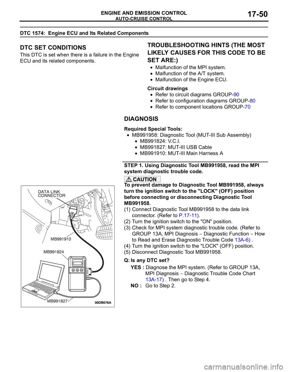
STEP 1. Using Diagnostic Tool MB991958, read the MPI
system diagnostic trouble code.
To prevent damage to Diagnostic Tool MB991958, always
turn the ignition switch to the "LOCK" (OFF) position
before connecting or disconnecting Diagnostic Tool
MB991958.
(1) Connect Diagnostic Tool MB991958 to the data link
connector. (Refer to P.17-11).
(2) Turn the ignition switch to the "ON" position.
(3) Check for MPI system diagnostic trouble code. (Refer to
GROUP 13A, MPI Diagnosis
Diagnostic Function How
to Read and Erase Diagnostic Trouble Code 13A-6) .
(4) Turn the ignition switch to the "LOCK" (OFF) position.
(5) Disconnect Diagnostic Tool MB991958.
Q: Is any DTC set?
YES : Diagnose the MPI system. (Refer to GROUP 13A,
MPI Diagnosis
Diagnostic Trouble Code Chart
13A-17) . Then go to Step 4.
NO : Go to Step 2.
Page 1385 of 1500

AUTO-CRUISE CONTROL
ENGINE AND EMISSION CONTROL17-54
SYMPTOM PROCEDURES
INSPECTION PROCEDURE 1: When the Brake Pedal is Depressed, Auto-cruise Control System is not
Cancelled.
.
COMMENT
The stoplamp switch circuit is suspected.
.
TROUBLESHOOTING HINTS (THE MOST
LIKELY CAUSES FOR THIS CASE:)
Malfunction of the stoplamp switch.
Damaged harness or connector.
Malfunction of the Engine ECU.
Circuit drawings
Refer to circuit diagrams GROUP-90
Refer to configuration diagrams GROUP-80
Refer to component locations GROUP-70
DIAGNOSIS
Refer to P.17-35, Diagnostic Trouble Code Procedures DTC
22: Stoplamp Switch System.
INSPECTION PROCEDURE 2: When the Selector Lever is Moved to "N" Range, Auto-cruise Control
System is not Cancelled.
.
COMMENT
The transmission inhibitor switch circuit is suspected.
.
TROUBLESHOOTING HINTS (THE MOST
LIKELY CAUSES FOR THIS CASE:)
Malfunction of the transmission inhibitor switch.
Damaged harness or connector.
Malfunction of the Engine ECU.
Malfunction of A/T ECU.
Circuit drawings
Refer to circuit diagrams GROUP-90
Refer to configuration diagrams GROUP-80
Refer to component locations GROUP-70
DIAGNOSIS
Refer to GROUP 23A, A/T Diagnosis Diagnostic Trouble
Code Procedures
DTC 0705: Transmission Inhibitor Switch
System (Open/short Circuit) P.23A-97.