Page 1474 of 1500

AUTOMATIC TRANSMISSION DIAGNOSIS
AUTOMATIC TRANSMISSION23A-15
To prevent damage to diagnostic tool MB991958, always
turn the ignition switch to the "LOCK" (OFF) position
before connecting or disconnecting diagnostic tool
MB991958.
NOTE: If the battery voltage is low, diagnostic trouble codes
will not be set. Check the battery if diagnostic tool
MB991958 does not display.
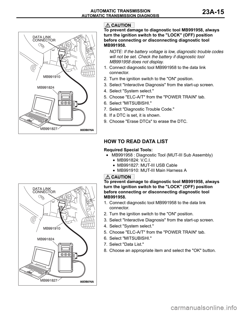
1. Connect diagnostic tool MB991958 to the data link
connector.
2. Turn the ignition switch to the "ON" position.
3. Select "Interactive Diagnosis" from the start-up screen.
4. Select "System select."
5. Choose "ELC-A/T" from the "POWER TRAIN" tab.
6. Select "MITSUBISHI."
7. Select "Diagnostic Trouble Code."
8. If a DTC is set, it is shown.
9. Choose "Erase DTCs" to erase the DTC.
HOW TO READ DATA LIST
Required Special Tools:
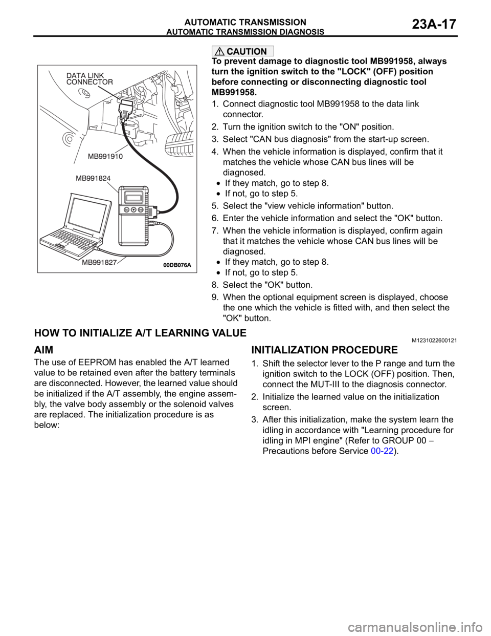
MB991958 : Diagnostic Tool (MUT-III Sub Assembly)
MB991824: V.C.I.
MB991827: MUT-III USB Cable
MB991910: MUT-III Main Harness A
To prevent damage to diagnostic tool MB991958, always
turn the ignition switch to the "LOCK" (OFF) position
before connecting or disconnecting diagnostic tool
MB991958.
1. Connect diagnostic tool MB991958 to the data link
connector.
2. Turn the ignition switch to the "ON" position.
3. Select "Interactive Diagnosis" from the start-up screen.
4. Select "System select."
5. Choose "ELC-A/T" from the "POWER TRAIN" tab.
6. Select "MITSUBISHI."
7. Select "Data List."
8. Choose an appropriate item and select the "OK" button.
Page 1476 of 1500

AUTOMATIC TRANSMISSION DIAGNOSIS
AUTOMATIC TRANSMISSION23A-17
To prevent damage to diagnostic tool MB991958, always
turn the ignition switch to the "LOCK" (OFF) position
before connecting or disconnecting diagnostic tool
MB991958.
1. Connect diagnostic tool MB991958 to the data link
connector.
2. Turn the ignition switch to the "ON" position.
3. Select "CAN bus diagnosis" from the start-up screen.
4. When the vehicle information is displayed, confirm that it
matches the vehicle whose CAN bus lines will be
diagnosed.
If they match, go to step 8.
If not, go to step 5.
5. Select the "view vehicle information" button.
6. Enter the vehicle information and select the "OK" button.
7. When the vehicle information is displayed, confirm again
that it matches the vehicle whose CAN bus lines will be
diagnosed.
If they match, go to step 8.
If not, go to step 5.
8. Select the "OK" button.
9. When the optional equipment screen is displayed, choose
the one which the vehicle is fitted with, and then select the
"OK" button.
HOW TO INITIALIZE A/T LEARNING VALUEM1231022600121
AIM
The use of EEPROM has enabled the A/T learned
value to be retained even after the battery terminals
are disconnected. However, the learned value should
be initialized if the A/T assembly, the engine assem-
bly, the valve body assembly or the solenoid valves
are replaced. The initialization procedure is as
below:
INITIALIZATION PROCEDURE
1. Shift the selector lever to the P range and turn the
ignition switch to the LOCK (OFF) position. Then,
connect the MUT-III to the diagnosis connector.
2. Initialize the learned value on the initialization
screen.
3. After this initialization, make the system learn the
idling in accordance with "Learning procedure for
idling in MPI engine" (Refer to GROUP 00
Precautions before Service 00-22).
Page 1481 of 1500

AUTOMATIC TRANSMISSION DIAGNOSIS
AUTOMATIC TRANSMISSION23A-22
7 Transmission
range: 3 (on a
flat and straight
road)Transmission range
and vehicle speed
(1) Driving at speed
of 60 km/h in 3rd
gear
(2) Driving at
constant speed of 60
km/h
(3) Release
accelerator pedal
(Speed under 50
km/hData list No.17
(2) 70
99.6%
(3) 70
99.6% to 0%Damper
control
clutch
solenoid
valve duty
%Damper control
clutch solenoid
system
(P.23A-185,
P.23A-201,
P.23A-204).
Data list No.10
(2) 100 to 300 r/min
(3) The value
changes from (2)Damper
control
clutch
amount of
slippage
8 Use the
diagnostic tool
MB991958
(MUT-III sub
assembly) to
stop the
INVECS-II
function
Transmission
range: D (on a
flat and straight
road)(1)Accelerate to 5th
gear at a throttle
position sensor
output of 1.5 V
(accelerator opening
angle of 25%)
(2)Slowly decelerate
to a stop
(3)Accelerate to 5th
gear at a throttle
position sensor
output of 2.5 V
(accelerator opening
angle of 50%)Data list No.11, 6
The shifting points
correspond with the
diagnostic tool
display and the TP
sensor voltage
(opening angle) and
output shaft speed,
which are shown in
the standard shift
patternMalfunction
when
shiftingShift shock and
slipping
(P.23A-236).
Does not
shift
according
to
instructionsEarly or late
shifting in all
gears
(P.23A-239).
Early or late
shifting in some
gears
(P.23A-242).
STEP CONDITION
BEFORE
TEST/OPERATIONTEST/OPERATION STANDARD INSPECTION
ITEMINSPECTION
PROCEDURE
PA G E
Page 1496 of 1500

AUTOMATIC TRANSMISSION DIAGNOSIS
AUTOMATIC TRANSMISSION23A-37
STEP 1. Using diagnostic tool MB991958, check data list
item 7: Transmission Fluid Temperature Sensor.
To prevent damage to diagnostic tool MB991958, always
turn the ignition switch to the "LOCK" (OFF) position
before connecting or disconnecting diagnostic tool
MB991958.
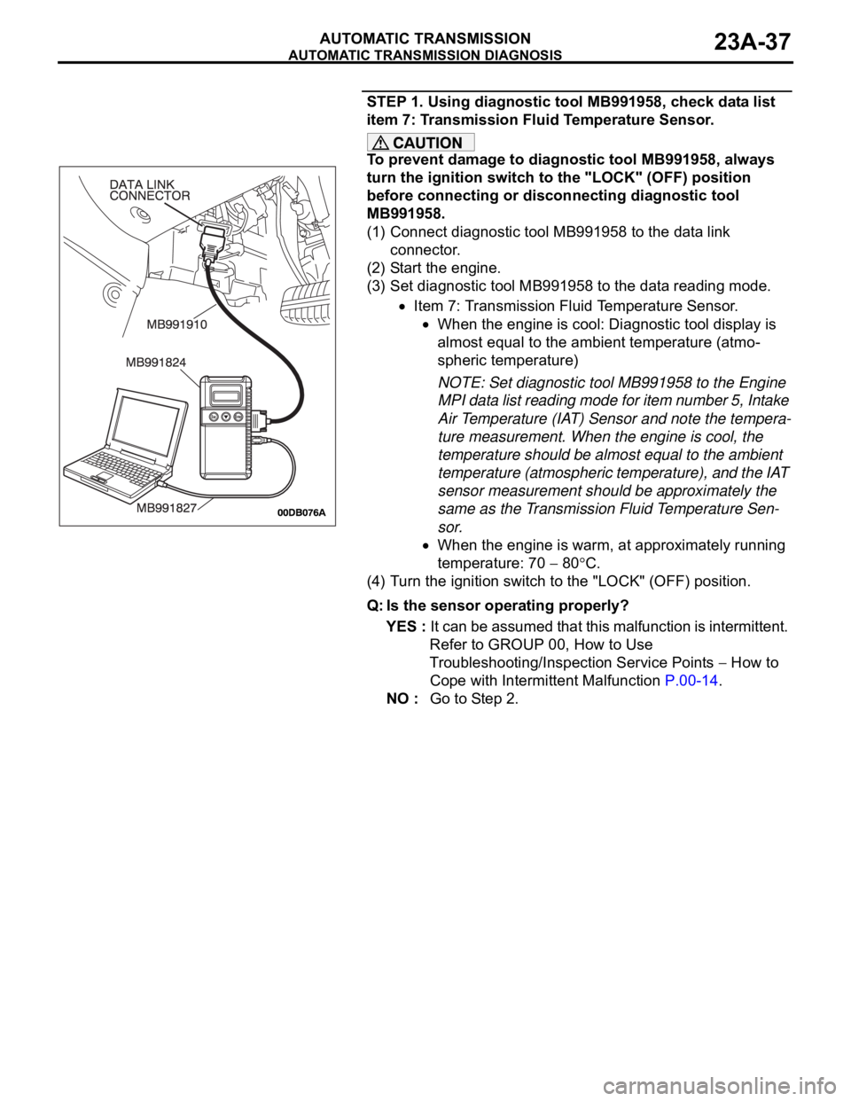
(1) Connect diagnostic tool MB991958 to the data link
connector.
(2) Start the engine.
(3) Set diagnostic tool MB991958 to the data reading mode.
Item 7: Transmission Fluid Temperature Sensor.
When the engine is cool: Diagnostic tool display is
almost equal to the ambient temperature (atmo-
spheric temperature)
NOTE: Set diagnostic tool MB991958 to the Engine
MPI data list reading mode for item number 5, Intake
Air Temperature (IAT) Sensor and note the tempera-
ture measurement. When the engine is cool, the
temperature should be almost equal to the ambient
temperature (atmospheric temperature), and the IAT
sensor measurement should be approximately the
same as the Transmission Fluid Temperature Sen-
sor.
When the engine is warm, at approximately running
temperature: 70
80C.
(4) Turn the ignition switch to the "LOCK" (OFF) position.
Q: Is the sensor operating properly?
YES : It can be assumed that this malfunction is intermittent.
Refer to GROUP 00, How to Use
Troubleshooting/Inspection Service Points
How to
Cope with Intermittent Malfunction P.00-14.
NO : Go to Step 2.
Page 1500 of 1500

AUTOMATIC TRANSMISSION DIAGNOSIS
AUTOMATIC TRANSMISSION23A-41
STEP 6. Using diagnostic tool MB991958, check data list
item 7: Transmission Fluid Temperature Sensor.
To prevent damage to diagnostic tool MB991958, always
turn the ignition switch to the "LOCK" (OFF) position
before connecting or disconnecting diagnostic tool
MB991958.
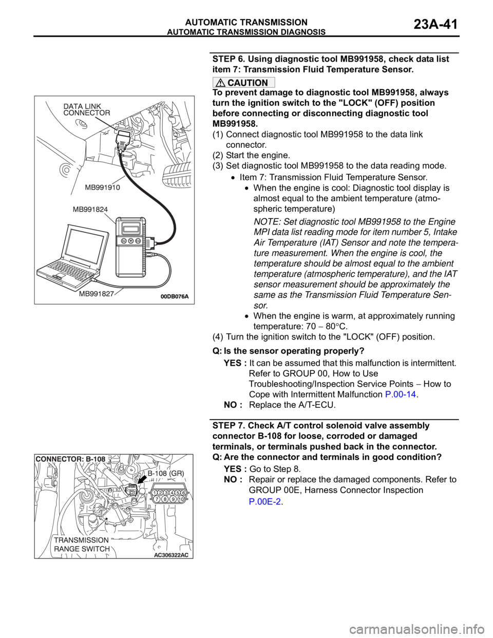
(1) Connect diagnostic tool MB991958 to the data link
connector.
(2) Start the engine.
(3) Set diagnostic tool MB991958 to the data reading mode.
Item 7: Transmission Fluid Temperature Sensor.
When the engine is cool: Diagnostic tool display is
almost equal to the ambient temperature (atmo-
spheric temperature)
NOTE: Set diagnostic tool MB991958 to the Engine
MPI data list reading mode for item number 5, Intake
Air Temperature (IAT) Sensor and note the tempera-
ture measurement. When the engine is cool, the
temperature should be almost equal to the ambient
temperature (atmospheric temperature), and the IAT
sensor measurement should be approximately the
same as the Transmission Fluid Temperature Sen-
sor.
When the engine is warm, at approximately running
temperature: 70
80C.
(4) Turn the ignition switch to the "LOCK" (OFF) position.
Q: Is the sensor operating properly?
YES : It can be assumed that this malfunction is intermittent.
Refer to GROUP 00, How to Use
Troubleshooting/Inspection Service Points
How to
Cope with Intermittent Malfunction P.00-14.
NO : Replace the A/T-ECU.
STEP 7. Check A/T control solenoid valve assembly
connector B-108 for loose, corroded or damaged
terminals, or terminals pushed back in the connector.
Q: Are the connector and terminals in good condition?
YES : Go to Step 8.
NO : Repair or replace the damaged components. Refer to
GROUP 00E, Harness Connector Inspection
P.00E-2.