2005 MITSUBISHI 380 Battery
[x] Cancel search: BatteryPage 1272 of 1500
MAINTENANCE SERVICE
GENERAL00-51
18. SUSPENSION SYSTEM (INSPECT FOR
LOOSENESS AND DAMAGE)
M1001009600048
Visually inspect the front/rear suspension components for dete-
rioration and damage. Re-tighten the front/rear suspension
components retaining bolts to specified torque.
19. SRS AIR BAG (INSPECT FOR SRS SYSTEM)M1001003700326
The entire SRS including air bag and pre-tensioner seat belt
must be inspected by an authorized MITSUBISHI MOTORS
dealer 10 years.
SRS WARNING LIGHT CHECK
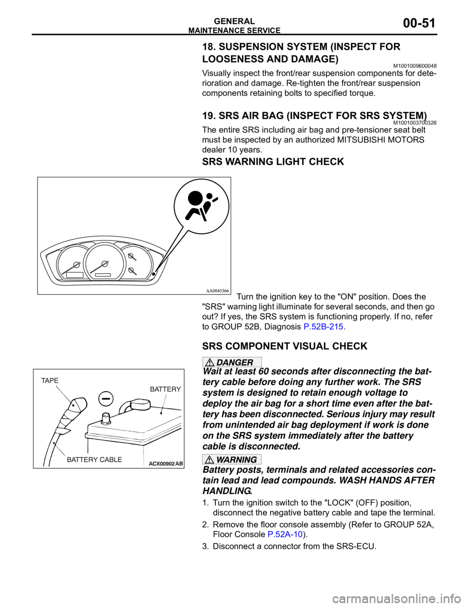
Turn the ignition key to the "ON" position. Does the
"SRS" warning light illuminate for several seconds, and then go
out? If yes, the SRS system is functioning properly. If no, refer
to GROUP 52B, Diagnosis P.52B-215.
SRS COMPONENT VISUAL CHECK
Wait at least 60 seconds after disconnecting the bat-
tery cable before doing any further work. The SRS
system is designed to retain enough voltage to
deploy the air bag for a short time even after the bat-
tery has been disconnected. Serious injury may result
from unintended air bag deployment if work is done
on the SRS system immediately after the battery
cable is disconnected.
Battery posts, terminals and related accessories con-
tain lead and lead compounds. WASH HANDS AFTER
HANDLING.
1. Turn the ignition switch to the "LOCK" (OFF) position,
disconnect the negative battery cable and tape the terminal.
2. Remove the floor console assembly (Refer to GROUP 52A,
Floor Console P.52A-10).
3. Disconnect a connector from the SRS-ECU.
Page 1283 of 1500
TRACTION CONTROL SYSTEM (TCL) DIAGNOSIS
TRACTION CONTROL SYSTEM (TCL)13C-4
To prevent damage to diagnostic tool MB991958, always
turn the ignition switch to the "LOCK" (OFF) position
before connecting or disconnecting diagnostic tool
MB991958.
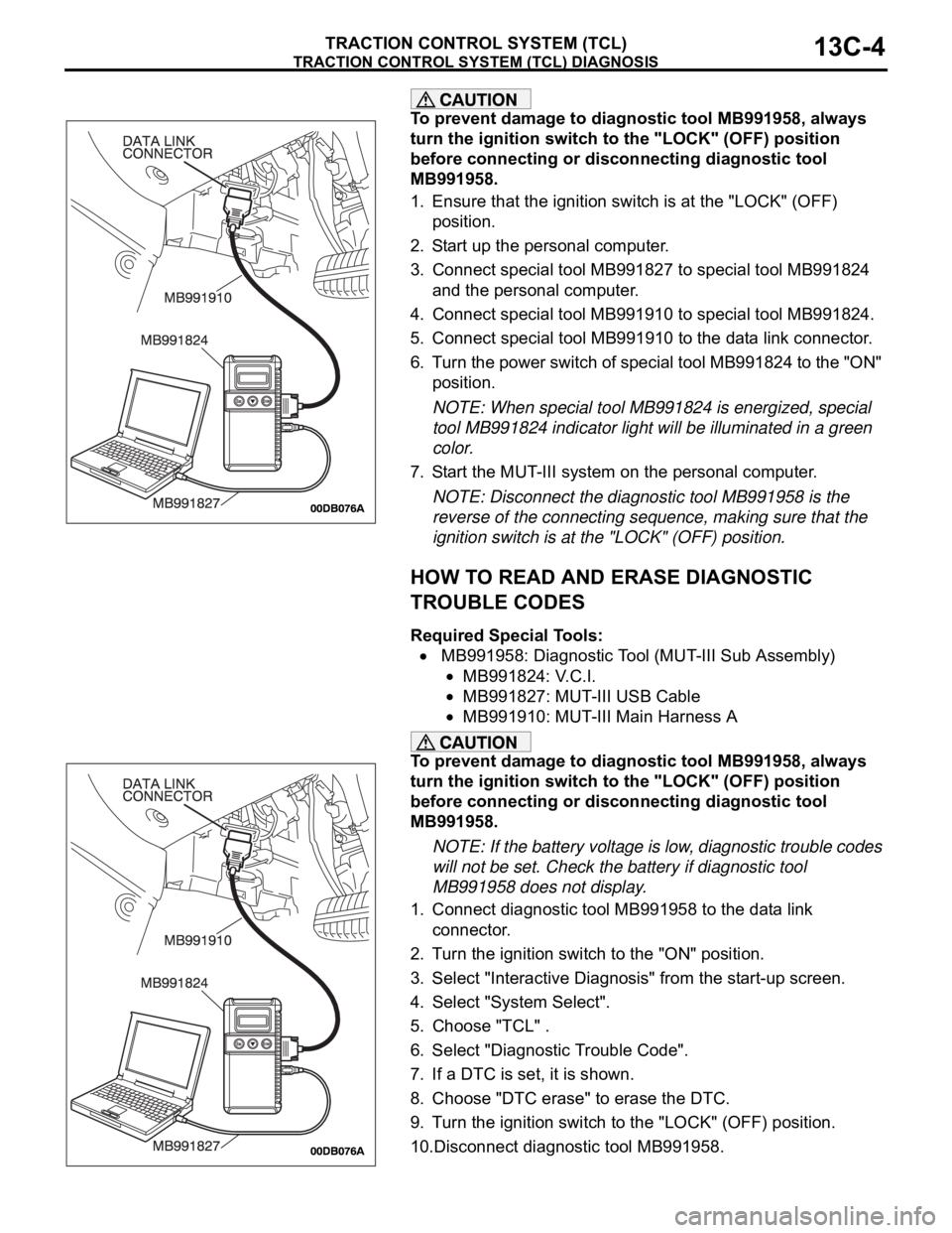
1. Ensure that the ignition switch is at the "LOCK" (OFF)
position.
2. Start up the personal computer.
3. Connect special tool MB991827 to special tool MB991824
and the personal computer.
4. Connect special tool MB991910 to special tool MB991824.
5. Connect special tool MB991910 to the data link connector.
6. Turn the power switch of special tool MB991824 to the "ON"
position.
NOTE: When special tool MB991824 is energized, special
tool MB991824 indicator light will be illuminated in a green
color.
7. Start the MUT-III system on the personal computer.
NOTE: Disconnect the diagnostic tool MB991958 is the
reverse of the connecting sequence, making sure that the
ignition switch is at the "LOCK" (OFF) position.
HOW TO READ AND ERASE DIAGNOSTIC
TROUBLE CODES
Required Special Tools:
MB991958: Diagnostic Tool (MUT-III Sub Assembly)
MB991824: V.C.I.
MB991827: MUT-III USB Cable
MB991910: MUT-III Main Harness A
To prevent damage to diagnostic tool MB991958, always
turn the ignition switch to the "LOCK" (OFF) position
before connecting or disconnecting diagnostic tool
MB991958.
NOTE: If the battery voltage is low, diagnostic trouble codes
will not be set. Check the battery if diagnostic tool
MB991958 does not display.
1. Connect diagnostic tool MB991958 to the data link
connector.
2. Turn the ignition switch to the "ON" position.
3. Select "Interactive Diagnosis" from the start-up screen.
4. Select "System Select".
5. Choose "TCL" .
6. Select "Diagnostic Trouble Code".
7. If a DTC is set, it is shown.
8. Choose "DTC erase" to erase the DTC.
9. Turn the ignition switch to the "LOCK" (OFF) position.
10.Disconnect diagnostic tool MB991958.
Page 1315 of 1500

TRACTION CONTROL SYSTEM (TCL) DIAGNOSIS
TRACTION CONTROL SYSTEM (TCL)13C-36
DATA LIST REFERENCE TABLEM1136003500071
NOTE: If the ABS-8 ECU or the active wheel
speed sensor are disconnected, or if the wiring is
an open/ short circuit, the ABS 8 ECU will shut
off power supply to the respective wheel speed
sensor. All other wheel speed sensors will oper-
ate normally. To restore the power supply, the
ignition switch must be turned to the "OFF" posi-
tion then to the "ON" position again.The following items can be read by the diagnostic
tool from the ABS/TCL-ECU input data. (Refer to
P.13C-3).
NOTE: Since the TCL is controlled with the same ABS/TCL-ECU used to control the ABS, the stoplight switch
check item (No.6) used only for the ABS also appear.MUT-III
DIAGNOSTI
C TOOL
DISPLAYITEM
NO.CHECK ITEM CHECKING REQUIREMENTS NORMAL
VA L U E
FL wheel
speed sensor01 Front left wheel speed sensor Drive the vehicle Vehicle speeds
displayed on the
speedometer
and diagnostic
tool are identical. FR wheel
speed sensor02 Front right wheel speed sensor
RL wheel
speed sensor03 Rear left wheel speed sensor
RR wheel
speed sensor04 Rear right left wheel speed
sensor
Power supply
voltage05 ABS/TCL-ECU power supply
voltageIgnition switch power supply
voltageBattery positive
voltage
Stoplamp
switch
(input)*06 Stoplamp switch Depress the brake pedal. ON
Release the brake pedal. OFF
Stoplamp
switch*13 Stoplamp switch Depress the brake pedal. ON
Release the brake pedal. OFF
Pump motor 21 Pump motor When the ABS outputs the
operation permission signal
during drivingON
When the ABS outputs the
operation permission signal
during drivingOFF
Valve relay 30 Valve relayWhen the ABS outputs the
operation permission signal
during drivingON
When the ABS outputs the
operation permission signal
during drivingOFF
TCL mode 35 TCL operation When the TCL outputs the
operation permission signal
during drivingON
When the TCL outputs the
operation inhibition signal
during drivingOFF
Page 1317 of 1500
TRACTION CONTROL SYSTEM (TCL) DIAGNOSIS
TRACTION CONTROL SYSTEM (TCL)13C-38
CHECK AT ABS/TCL-ECU CONNECTOR: A-02
RESISTANCE AND TERMINAL VOLTAGE
M1136003800072
RESISTANCE AND TERMINAL VOLTAGE CHECK
CHART
.
Required Special Tools:
MB991219: Inspection Test Harness
MB991223: Harness Set
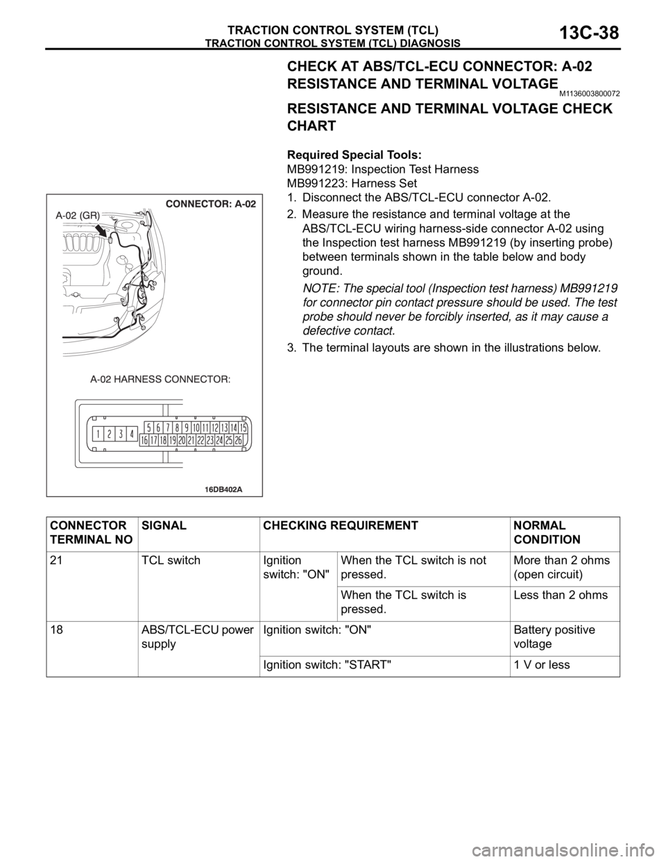
1. Disconnect the ABS/TCL-ECU connector A-02.
2. Measure the resistance and terminal voltage at the
ABS/TCL-ECU wiring harness-side connector A-02 using
the Inspection test harness MB991219 (by inserting probe)
between terminals shown in the table below and body
ground.
NOTE: The special tool (Inspection test harness) MB991219
for connector pin contact pressure should be used. The test
probe should never be forcibly inserted, as it may cause a
defective contact.
3. The terminal layouts are shown in the illustrations below.
CONNECTOR
TERMINAL NOSIGNAL CHECKING REQUIREMENT NORMAL
CONDITION
21 TCL switch Ignition
switch: "ON" When the TCL switch is not
pressed.More than 2 ohms
(open circuit)
When the TCL switch is
pressed.Less than 2 ohms
18 ABS/TCL-ECU power
supplyIgnition switch: "ON" Battery positive
voltage
Ignition switch: "START" 1 V or less
Page 1343 of 1500
AUTO-CRUISE CONTROL
ENGINE AND EMISSION CONTROL17-12
To prevent damage to Diagnostic Tool MB991958, always
turn the ignition switch to the "LOCK" (OFF) position
before connecting or disconnecting Diagnostic Tool
MB991958.
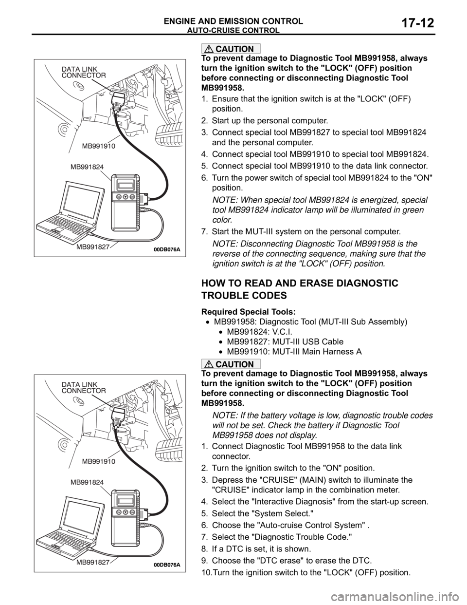
1. Ensure that the ignition switch is at the "LOCK" (OFF)
position.
2. Start up the personal computer.
3. Connect special tool MB991827 to special tool MB991824
and the personal computer.
4. Connect special tool MB991910 to special tool MB991824.
5. Connect special tool MB991910 to the data link connector.
6. Turn the power switch of special tool MB991824 to the "ON"
position.
NOTE: When special tool MB991824 is energized, special
tool MB991824 indicator lamp will be illuminated in green
color.
7. Start the MUT-III system on the personal computer.
NOTE: Disconnecting Diagnostic Tool MB991958 is the
reverse of the connecting sequence, making sure that the
ignition switch is at the "LOCK" (OFF) position.
HOW TO READ AND ERASE DIAGNOSTIC
TROUBLE CODES
Required Special Tools:
MB991958: Diagnostic Tool (MUT-III Sub Assembly)
MB991824: V.C.I.
MB991827: MUT-III USB Cable
MB991910: MUT-III Main Harness A
To prevent damage to Diagnostic Tool MB991958, always
turn the ignition switch to the "LOCK" (OFF) position
before connecting or disconnecting Diagnostic Tool
MB991958.
NOTE: If the battery voltage is low, diagnostic trouble codes
will not be set. Check the battery if Diagnostic Tool
MB991958 does not display.
1. Connect Diagnostic Tool MB991958 to the data link
connector.
2. Turn the ignition switch to the "ON" position.
3. Depress the "CRUISE" (MAIN) switch to illuminate the
"CRUISE" indicator lamp in the combination meter.
4. Select the "Interactive Diagnosis" from the start-up screen.
5. Select the "System Select."
6. Choose the "Auto-cruise Control System" .
7. Select the "Diagnostic Trouble Code."
8. If a DTC is set, it is shown.
9. Choose the "DTC erase" to erase the DTC.
10.Turn the ignition switch to the "LOCK" (OFF) position.
Page 1348 of 1500
AUTO-CRUISE CONTROL
ENGINE AND EMISSION CONTROL17-17
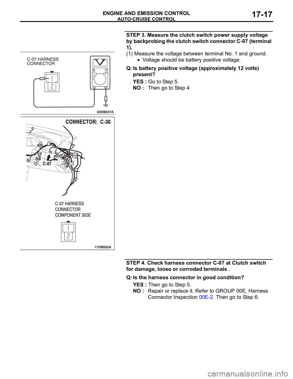
STEP 3. Measure the clutch switch power supply voltage
by backprobing the clutch switch connector C-07 (terminal
1).
(1) Measure the voltage between terminal No. 1 and ground.
Voltage should be battery positive voltage.
Q: Is battery positive voltage (approximately 12 volts)
present?
YES : Go to Step 5.
NO : Then go to Step 4.
STEP 4. Check harness connector C-07 at Clutch switch
for damage, loose or corroded terminals .
Q: Is the harness connector in good condition?
YES : Then go to Step 5.
NO : Repair or replace it. Refer to GROUP 00E, Harness
Connector Inspection 00E-2. Then go to Step 6.
Page 1349 of 1500
AUTO-CRUISE CONTROL
ENGINE AND EMISSION CONTROL17-18
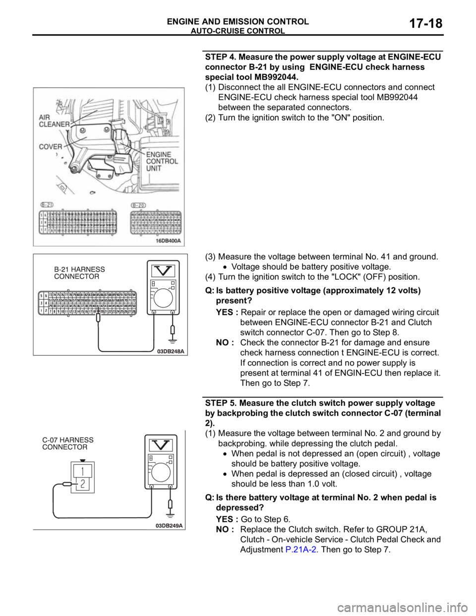
STEP 4. Measure the power supply voltage at ENGINE-ECU
connector B-21 by using ENGINE-ECU check harness
special tool MB992044.
(1) Disconnect the all ENGINE-ECU connectors and connect
ENGINE-ECU check harness special tool MB992044
between the separated connectors.
(2) Turn the ignition switch to the "ON" position.
(3) Measure the voltage between terminal No. 41 and ground.
Voltage should be battery positive voltage.
(4) Turn the ignition switch to the "LOCK" (OFF) position.
Q: Is battery positive voltage (approximately 12 volts)
present?
YES : Repair or replace the open or damaged wiring circuit
between ENGINE-ECU connector B-21 and Clutch
switch connector C-07. Then go to Step 8.
NO : Check the connector B-21 for damage and ensure
check harness connection t ENGINE-ECU is correct.
If connection is correct and no power supply is
present at terminal 41 of ENGIN-ECU then replace it.
Then go to Step 7.
STEP 5. Measure the clutch switch power supply voltage
by backprobing the clutch switch connector C-07 (terminal
2).
(1) Measure the voltage between terminal No. 2 and ground by
backprobing. while depressing the clutch pedal.
When pedal is not depressed an (open circuit) , voltage
should be battery positive voltage.
When pedal is depressed an (closed circuit) , voltage
should be less than 1.0 volt.
Q: Is there battery voltage at terminal No. 2 when pedal is
depressed?
YES : Go to Step 6.
NO : Replace the Clutch switch. Refer to GROUP 21A,
Clutch - On-vehicle Service - Clutch Pedal Check and
Adjustment P.21A-2. Then go to Step 7.
Page 1354 of 1500
AUTO-CRUISE CONTROL
ENGINE AND EMISSION CONTROL17-23
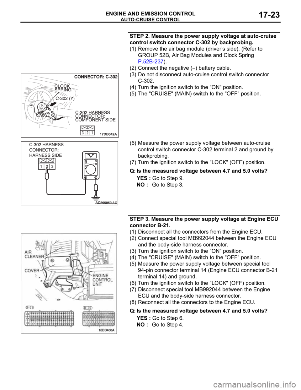
STEP 2. Measure the power supply voltage at auto-cruise
control switch connector C-302 by backprobing.
(1) Remove the air bag module (driver’s side). (Refer to
GROUP 52B, Air Bag Modules and Clock Spring
P.52B-237).
(2) Connect the negative (
) battery cable.
(3) Do not disconnect auto-cruise control switch connector
C-302.
(4) Turn the ignition switch to the "ON" position.
(5) The "CRUISE" (MAIN) switch to the "OFF" position.
(6) Measure the power supply voltage between auto-cruise
control switch connector C-302 terminal 2 and ground by
backprobing.
(7) Turn the ignition switch to the "LOCK" (OFF) position.
Q: Is the measured voltage between 4.7 and 5.0 volts?
YES : Go to Step 9.
NO : Go to Step 3.
STEP 3. Measure the power supply voltage at Engine ECU
connector B-21.
(1) Disconnect all the connectors from the Engine ECU.
(2) Connect special tool MB992044 between the Engine ECU
and the body-side harness connector.
(3) Turn the ignition switch to the "ON" position.
(4) The "CRUISE" (MAIN) switch to the "OFF" position.
(5) Measure the power supply voltage between special tool
94-pin connector terminal 14 (Engine ECU connector B-21
terminal 14) and ground.
(6) Turn the ignition switch to the "LOCK" (OFF) position.
(7) Disconnect special tool MB992044 between the Engine
ECU and the body-side harness connector.
(8) Reconnect all the connectors to the Engine ECU.
Q: Is the measured voltage between 4.7 and 5.0 volts?
YES : Go to Step 6.
NO : Go to Step 4.