2005 MITSUBISHI 380 diagnostic connector
[x] Cancel search: diagnostic connectorPage 983 of 1500

CHARGING SYSTEM
ENGINE ELECTRICAL16-6
SPECIAL TOOLM1161000600486
TOOL TOOL NUMBER AND
NAMESUPERSESSION APPLICATION
Diagnostic tool (MUT-III)
A: MB991824
Ve h i c l e
communication
interface (V.C.I.)
B: MB991827
MUT-III USB cable
C: MB991910
MUT-III main harness
A (Vehicles with CAN
communication
system)
D: MB991911
MUT-III main harness
B (Vehicles without
CAN communication
system)
E: MB991914
MUT-III main harness
C (for Daimler Chrysler
models only)
F: MB991825
MUT-III measurement
adapter
G: MB991826
MUT-III trigger
harnessMB991824-KIT
NOTE: G: MB991826
MUT-III Trigger Harness
is not necessary when
pushing V.C.I. ENTER
key.Checking of engine
speed
For vehicles with CAN
communication, use
MUT-III main harness A
to send simulated
vehicle speed. If you
connect MUT-III main
harness B instead, the
CAN communication
does not function
correctly.
MB998467
Alternator harness
connectorMIT530
Micrd 530 charging
system tester.Checking of alternator
("S" terminal voltage)
Page 987 of 1500

CHARGING SYSTEM
ENGINE ELECTRICAL16-10
REGULATED VOLTAGE TESTM1161001100666
Required Special Tools:
: Diagnostic Tool (MUT-III)
MB991824: V.C.I.
MB991827: MUT-III USB Cable
MB991910: MUT-III Main Harness A
MB998467: Alternator Harness Connector
This test determines whether the voltage regulator is
correctly controlling the alternator output voltage.
Battery posts, terminals and related acces-
sories contain lead and lead compounds.
WASH HANDS AFTER HANDLING.
1. Always be sure to check the following before the
test:
Alternator installation
Check to be sure that the battery installed in the
vehicle is fully charged. (Refer to GROUP 54A,
Chassis Electrical
Battery On-vehicle Service
Battery Check P.54A-5.)
Alternator drive belt tension (Refer to GROUP 00,
General
Maintenance Service Drive Belts
(For Alternator, Power Steering Pump and Air
Conditioning) (Check) P.00-39.)
Fusible link
Abnormal noise from the alternator while the
engine is running.2. Turn the ignition switch to the "LOCK" (OFF)
position.
3. Disconnect the negative battery cable.
4. Use the special tool (Alternator harness
connector: MB998467) to connect a digital-type
voltmeter between the alternator "S" terminal and
ground. (Connect the positive lead of the
voltmeter to the "S" terminal, and then connect the
negative lead of the voltmeter to a secure ground
or to the negative battery terminal.)
5. Connect a clamp-type DC test ammeter with a
range of 0
120 A to the alternator "B" terminal
output wire.
6. Reconnect the negative battery cable.
7. Connect an engine tachometer, or diagnostic tool.
8. Turn the ignition switch to the "ON" position and
check that the reading on the voltmeter is equal to
the battery positive voltage.
NOTE: If the voltage is 0 V, the cause is probably
an open circuit in the wire or fusible link between
the alternator "S" terminal and the battery positive
terminal or malfunctioning voltmeter.
9. Check to be sure that all lights and accessories
are off.
10.Start the engine.
Page 1008 of 1500

IGNITION SYSTEM
ENGINE ELECTRICAL16-31
ON-VEHICLE SERVICE
KNOCK CONTROL SYSTEM CHECKM1163001800081
Check the knock sensor circuit if diagnostic trouble code, No.
P0325 is shown.
Refer to GROUP 13B, Multiport Fuel Injection (MPI)
Multiport
Fuel Injection (MPI) Diagnosis
Diagnostic Trouble Code Pro-
cedures
DTC P0325 : Knock Sensor Circuit 13A-346.
IGNITION COIL CHECK M1163001200380
Check by the following procedure, and replace the coil if there
is a malfunction.
.
PRIMARY COIL AND IGNITION POWER
TRANSISTOR CONTINUITY CHECK
NOTE: No test can be performed on the Primary side of coil.
.
SECONDARY COIL CHECK
NOTE: It is impossible to check the secondary coil through the
continuity check as a diode is integrated in the secondary coil
circuit of this ignition coil. Accordingly, check the secondary coil
in the following procedure.
1. Disconnect the ignition coil connector.
2. Remove the ignition coil and install a new spark plug to the
ignition coil.
3. Connect the ignition coil connector.
4. Disable vehicle fuel pump by removing fuel pump relay or
disconnecting fuel pump connector D-18 (under rear seat).
5. Ground the side electrode of the spark plug and crank the
engine.
6. Check that spark is produced between the electrodes of the
spark plug.
7. If no spark is produced, replace the ignition coil with a new
one and recheck.
8. If spark is produced with the new ignition coil, replace the
old one as it is faulty. If no spark is produced again, the
ignition circuit is suspected as faulty. Check the ignition
circuit.
Page 1049 of 1500
WINDSHIELD WIPER AND WASHER
EXTERIOR51-16
If the windshield intermittent wiper interval control is operated,
the wiper interval should change.
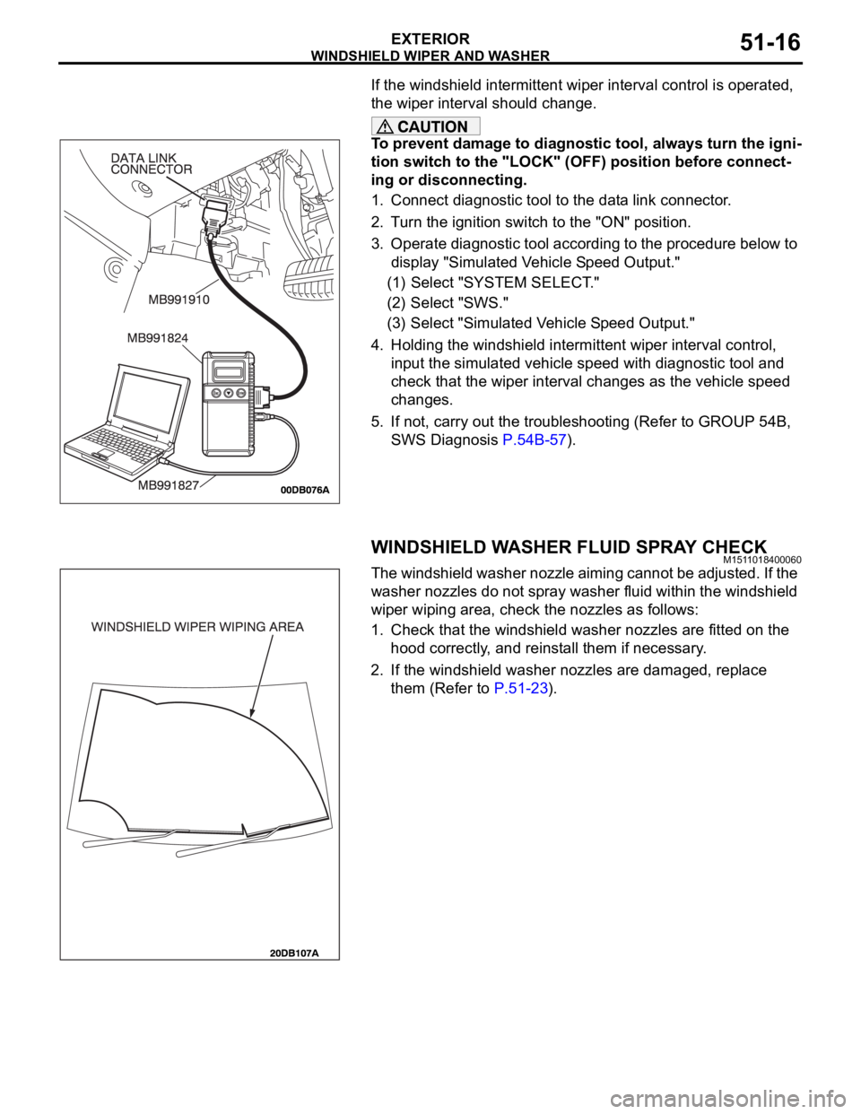
To prevent damage to diagnostic tool, always turn the igni-
tion switch to the "LOCK" (OFF) position before connect-
ing or disconnecting.
1. Connect diagnostic tool to the data link connector.
2. Turn the ignition switch to the "ON" position.
3. Operate diagnostic tool according to the procedure below to
display "Simulated Vehicle Speed Output."
(1) Select "SYSTEM SELECT."
(2) Select "SWS."
(3) Select "Simulated Vehicle Speed Output."
4. Holding the windshield intermittent wiper interval control,
input the simulated vehicle speed with diagnostic tool and
check that the wiper interval changes as the vehicle speed
changes.
5. If not, carry out the troubleshooting (Refer to GROUP 54B,
SWS Diagnosis P.54B-57).
WINDSHIELD WASHER FLUID SPRAY CHECKM1511018400060
The windshield washer nozzle aiming cannot be adjusted. If the
washer nozzles do not spray washer fluid within the windshield
wiper wiping area, check the nozzles as follows:
1. Check that the windshield washer nozzles are fitted on the
hood correctly, and reinstall them if necessary.
2. If the windshield washer nozzles are damaged, replace
them (Refer to P.51-23).
Page 1222 of 1500
00-1
GROUP 00
GENERAL
CONTENTS
HOW TO USE THIS MANUAL . . . . . .00-3
TROUBLESHOOTING GUIDELINES00-6
HOW TO USE TROUBLESHOOTING /
INSPECTION SERVICE POINTS. . . .00-7
TROUBLESHOOTING CONTENTS . . . . . . 00-7
HOW TO USE THE INSPECTION
PROCEDURES . . . . . . . . . . . . . . . . . . . . . . 00-9
CONNECTOR MEASUREMENT SERVICE
POINTS . . . . . . . . . . . . . . . . . . . . . . . . . . . . 00-11
CONNECTOR INSPECTION SERVICE
POINTS . . . . . . . . . . . . . . . . . . . . . . . . . . . . 00-13
HOW TO COPE WITH INTERMITTENT
MALFUNCTIONS . . . . . . . . . . . . . . . . . . . . 00-14
INSPECTION SERVICE POINTS
FOR A BLOWN FUSE . . . . . . . . . . . . . . . . 00-16
HOW TO TREAT CURRENT TROUBLE . . 00-16
HOW TO TREAT PAST TROUBLE . . . . . . 00-16
AFFILIATED DTC REFERENCE
TABLE . . . . . . . . . . . . . . . . . . . . . . . .00-17
VEHICLE IDENTIFICATION . . . . . . .00-18
VEHICLE IDENTIFICATION NUMBER . . . 00-18
VEHICLE INFORMATION NUMBER LIST 00-19
VEHICLE COMPLIANCE PLATE . . . . . . . . 00-19
VEHICLE DATA PLATE . . . . . . . . . . . . . . . 00-20
AUSTRALIAN DESIGN RULES . . . . . . . . . 00-20OPTION CODES . . . . . . . . . . . . . . . . . . . . . 00-21
EXPORT CODES . . . . . . . . . . . . . . . . . . . . 00-21
TYRE AND LOADING PLACARD . . . . . . . . 00-21
ENGINE MODEL STAMPING . . . . . . . . . . . 00-22
PRECAUTIONS BEFORE SERVICE .00-22
SUPPLEMENTAL RESTRAINT
SYSTEM (SRS . . . . . . . . . . . . . . . . . . . . . . 00-22
HOW TO PERFORM VEHICLE
IDENTIFICATION NUMBER (VIN) WRITING00-23
SERVICING ELECTRICAL SYSTEM . . . . . 00-24
VEHICLE WASHING . . . . . . . . . . . . . . . . . . 00-24
APPLICATION OF ANTI-CORROSION
AGENTS AND UNDERCOATS . . . . . . . . . . 00-25
DIAGNOSTIC TOOL (MUT-III) . . . . . . . . . . 00-25
TOWING AND HOISTING. . . . . . . . . .00-26
GENERAL DATA AND
SPECIFICATIONS . . . . . . . . . . . . . . .00-31
TIGHTENING TORQUE . . . . . . . . . . .00-32
LUBRICATION AND MAINTENANCE 00-34
RECOMMENDED LUBRICANTS AND
LUBRICANT CAPACITIES TABLE . .00-35
Continued on next page
Page 1228 of 1500
HOW TO USE TROUBLESHOOTING/INSPECTION SERVICE POINTS
GENERAL00-7
HOW TO USE TROUBLESHOOTING/INSPECTION SERVICE
POINTS
TROUBLESHOOTING CONTENTSM1001013300062
During diagnosis, a DTC code associated with
other system may be set when the ignition
switch is turned on with connector(s) discon-
nected. On completion, confirm all systems
for DTC code(s). If DTC code(s) are set, erase
them all.
When the DIAGNOSTIC TOOL (MUT-III)
detects a diagnostic trouble code, its display
informs users whether a mechanical problem
currently exists (“current trouble”) or whether
it existed before but normal operation has
been restored (“past trouble”). However, if an
MPI, TPMS or SRS airbag-related DTC is set,
“Active DTC/Stored DTC” is not displayed. In
this case, follow the diagnosis procedure for
current trouble.
If a trouble, detected in a CAN communica-
tion-capable system, can be reproduced,
diagnose the CAN bus lines (Refer to GROUP
54C, Can Bus Line Diagnostics Chart
P.54C-15 or P.54C-15).
Troubleshooting of electronic control systems for
which the MUT -III can be used follows the basic out-
line described below. Even in systems for which the
MUT-III cannot be used, part of these systems still
follow this outline.
1. STANDARD FLOW OF DIAGNOSTIC
TROUBLESHOOTING
Troubleshooting strategy is shown in each group.
2. SYSTEM OPERATION AND SYMPTOM
VERIFICATION TESTS
If verification of the symptom(s) is difficult, proce-
dures for checking operation and verifying symptoms
are shown.
3. DIAGNOSTIC FUNCTION
The following trouble code diagnoses are shown.
How to read diagnostic trouble codes
How to erase diagnostic trouble codes
Input inspection service points
4. DIAGNOSTIC TROUBLE CODE CHART
If the MUT-III displays a diagnostic trouble code, find
the applicable inspection procedure according to this
chart.
5. SYMPTOM CHART
If there are symptoms, even though the MUT-III
shows that no DTCs are set, inspection procedures
for each symptom will be found by using this chart.
6. DIAGNOSTIC TROUBLE CODE
PROCEDURES
Indicates the inspection procedures corresponding to
each diagnostic trouble code. (Refer to P.00-9).
7. SYMPTOM PROCEDURES
Indicates the inspection procedures corresponding to
each symptom listed in the Symptom Chart (Refer to
P.00-9).
8. SERVICE DATA REFERENCE TABLE
Inspection items and normal judgment values have
been provided in this chart as reference information.
9. CHECK AT ECU TERMINALS
Terminal numbers for the ECU connectors, inspec-
tion items, and standard values have been provided
in this chart as reference information.
.
TERMINAL VOLTAGE CHECKS
1. Use correct tool to check each pin location on the
ENGINE-ECU Check harnes MB992044 and
measure with voltmeter.
Short-circuiting the positive (+) test probe
between a connector terminal and ground could
damage the vehicle wiring, the sensor, the ECU,
or all three. Use care to prevent this!
2. Insert the correct terminal tool into each of the
ENGINE-ECU check harness connector
terminals, and measure the voltage while referring
to the check chart.
NOTE: Measure voltage with the ECU connectors
connected.
You may find it convenient to pull out the ECU to
make it easier to connect the ENGINE-ECU check
harness.
Page 1235 of 1500
HOW TO USE TROUBLESHOOTING/INSPECTION SERVICE POINTS
GENERAL00-14
CONNECTOR ENGAGEMENT INSPECTION
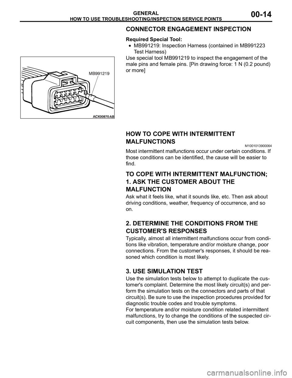
Required Special Tool:
MB991219: Inspection Harness (contained in MB991223
Test Harness)
Use special tool MB991219 to inspect the engagement of the
male pins and female pins. [Pin drawing force: 1 N (0.2 pound)
or more]
HOW TO COPE WITH INTERMITTENT
MALFUNCTIONS
M1001013900064
Most intermittent malfunctions occur under certain conditions. If
those conditions can be identified, the cause will be easier to
find.
.
TO COPE WITH INTERMITTENT MALFUNCTION;
1. ASK THE CUSTOMER ABOUT THE
MALFUNCTION
Ask what it feels like, what it sounds like, etc. Then ask about
driving conditions, weather, frequency of occurrence, and so
on.
.
2. DETERMINE THE CONDITIONS FROM THE
CUSTOMER'S RESPONSES
Typically, almost all intermittent malfunctions occur from condi-
tions like vibration, temperature and/or moisture change, poor
connections. From the customer's responses, it should be rea-
soned which condition is most likely.
.
3. USE SIMULATION TEST
Use the simulation tests below to attempt to duplicate the cus-
tomer's complaint. Determine the most likely circuit(s) and per-
form the simulation tests on the connectors and parts of that
circuit(s). Be sure to use the inspection procedures provided for
diagnostic trouble codes and trouble symptoms.
For temperature and/or moisture condition related intermittent
malfunctions, try to change the conditions of the suspected cir-
cuit components, then use the simulation tests below.
.
Page 1236 of 1500
HOW TO USE TROUBLESHOOTING/INSPECTION SERVICE POINTS
GENERAL00-15
4. VERIFY THE INTERMITTENT MALFUNCTION IS
ELIMINATED
Repair the malfunctioning part and try to duplicate the condi-
tion(s) again to verify the intermittent malfunction has been
eliminated.
.
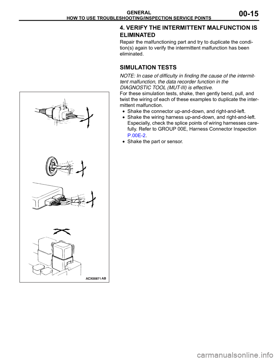
SIMULATION TESTS
NOTE: In case of difficulty in finding the cause of the intermit-
tent malfunction, the data recorder function in the
DIAGNOSTIC TOOL (MUT-III) is effective.
For these simulation tests, shake, then gently bend, pull, and
twist the wiring of each of these examples to duplicate the inter-
mittent malfunction.
Shake the connector up-and-down, and right-and-left.
Shake the wiring harness up-and-down, and right-and-left.
Especially, check the splice points of wiring harnesses care-
fully. Refer to GROUP 00E, Harness Connector Inspection
P.00E-2.
Shake the part or sensor.