Page 1146 of 1500

SUNROOF ASSEMBLY
BODY42-79
Sunroof timer mechanism
In cases except the following, the basic operation
and jam preventing mechanism will be maintained
for thirty seconds after the ignition switch is turned to
the LOCK (OFF) position. (Sunroof timer function)
If you open a door within that period (i.e. a door
switch is on), the sunroof timer function will be
cancelled immediately.
If you turn the ignition switch to the LOCK (OFF)
position while the timer is working, the sunroof
will continue moving until it closes fully, regard-
less of the time-out period. 05 AUTOMATIC
OPERATION
INTERRUPTION
(OPEN)A
1. Ignition switch: ON
2. Sunroof switch: OPEN or TILT-UPThe sunroof stops the
automatic opening
operation.
B
1. Ignition switch: ON
2. Sunroof switch: CLOSE/TILT DOWN (Push
the sunroof switch to the
CLOSE/TILT-DOWN position while the
sunroof is automatically opening and
release the switch within two seconds)The sunroof stops the
automatic opening
operation.
C
1. Ignition switch: ON
2. Sunroof switch: CLOSE/TILT DOWN (Push
the sunroof switch to the
CLOSE/TILT-DOWN position more than
two seconds while the sunroof is
automatically opening)The sunroof stops the
automatic opening
operation, and the sunroof
closes while the sunroof
switch is pushed to the
CLOSE/TILT-DOWN
position.
06 AUTOMATIC
OPERATION
INTERRUPTION
(TILT-UP)1. Ignition switch: ON
2. Sunroof switch: OPEN or TILT-UP, CLOSE/TILT
DOWNThe sunroof stops the
automatic opening
operation. NO. SUNROOF
FUNCTIONREQUIREMENTS FOR THE SUNROOF TO
FUNCTIONNORMAL OPERATION
Page 1154 of 1500

SPECIFICATIONS
BODY42-87
SERVICE SPECIFICATIONSM1421000300299
SEALANT AND ADHESIVESM1421000500204
ITEM STANDARD VALUE
Door inside handle knob play mm
(in)Front 26.1 - 58.1 (1.028 - 2.287) [Target
value 41 (1.61)]
Rear 30.3 - 58.1 (1.193 - 2.287) [Target
value 41 (1.61)]
Door inside handle lock knob stroke mm (in) 21.6 (0.850)
Door outside handle play mm (in) Front 10
3.5 (0.39 0.138)
Rear 11.2
4 (0.441 0.16)
Power window operation current A 5
1 [Power supply voltage 14.5
0.5V 25
C (77F)]
ITEM STANDARD VALUE
Roof lid glass operation current A 7 or less [at 20
C(68F)]
ITEM SPECIFIED ADHESIVE
Rear window glass 3 M
AAD part No. 8609 super fast urethane and 3 M AAD part No.
8608 super fast urethane primer or equivalent
Windshield
ITEM SPECIFIED SEALANT REMARK
Waterproof film 3 M
AAD Part No. 8633 or equivalent Ribbon sealer
ITEM SPECIFIED ADHESIVE TAPE
Front door opening outer
weatherstripAdhesive tape: Double-sided tape [7 mm (0.28 in) width, 85 mm (3.35
in) length and 0.8 mm (0.03 in) thickness]
Rear door opening outer
weatherstripAdhesive tape: Double-sided tape [7 mm (0.28 in) width, 50 mm (1.97
in) length and 0.8 mm (0.031 in) thickness]
ITEM SPECIFIED SEALANT REMARK
Trunk lid hinge 3 M
AAD part No. 8531 Heavy drip check sealer,
3 M
AAD part No. 8646 Automotive joint and
seam sealer or equivalentBody sealer
Page 1245 of 1500

PRECAUTIONS BEFORE SERVICE
GENERAL00-24
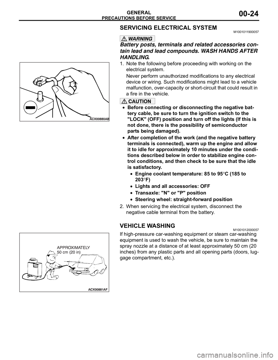
SERVICING ELECTRICAL SYSTEMM1001011900057
Battery posts, terminals and related accessories con-
tain lead and lead compounds. WASH HANDS AFTER
HANDLING.
1. Note the following before proceeding with working on the
electrical system.
Never perform unauthorized modifications to any electrical
device or wiring. Such modifications might lead to a vehicle
malfunction, over-capacity or short-circuit that could result in
a fire in the vehicle.
Before connecting or disconnecting the negative bat-
tery cable, be sure to turn the ignition switch to the
"LOCK" (OFF) position and turn off the lights (If this is
not done, there is the possibility of semiconductor
parts being damaged).
After completion of the work (and the negative battery
terminals is connected), warm up the engine and allow
it to idle for approximately 10 minutes under the condi-
tions described below in order to stabilize engine con-
trol conditions, and then check to be sure that the idle
is satisfactory.
Engine coolant temperature: 85 to 95C (185 to
203
F)
Lights and all accessories: OFF
Transaxle: "N" or "P" position
Steering wheel: straight-forward position
2. When servicing the electrical system, disconnect the
negative cable terminal from the battery.
VEHICLE WASHINGM1001012000057
If high-pressure car-washing equipment or steam car-washing
equipment is used to wash the vehicle, be sure to maintain the
spray nozzle at a distance of at least approximately 50 cm (20
inches) from any plastic parts and all opening parts (doors, lug-
gage compartment, etc.).
Page 1248 of 1500

TOWING AND HOISTING
GENERAL00-27
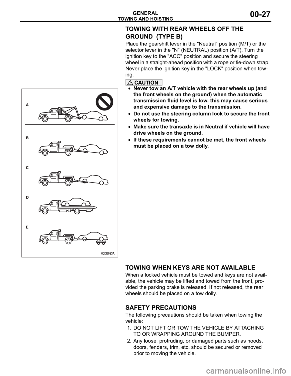
TOWING WITH REAR WHEELS OFF THE
GROUND (TYPE B)
Place the gearshift lever in the "Neutral" position (M/T) or the
selector lever in the "N" (NEUTRAL) position (A/T). Turn the
ignition key to the "ACC" position and secure the steering
wheel in a straight-ahead position with a rope or tie-down strap.
Never place the ignition key in the "LOCK" position when tow-
ing.
Never tow an A/T vehicle with the rear wheels up (and
the front wheels on the ground) when the automatic
transmission fluid level is low. this may cause serious
and expensive damage to the transmission.
Do not use the steering column lock to secure the front
wheels for towing.
Make sure the transaxle is in Neutral if vehicle will have
drive wheels on the ground.
If these requirements cannot be met, the front wheels
must be placed on a tow dolly.
.
TOWING WHEN KEYS ARE NOT AVAILABLE
When a locked vehicle must be towed and keys are not avail-
able, the vehicle may be lifted and towed from the front, pro-
vided the parking brake is released. If not released, the rear
wheels should be placed on a tow dolly.
.
SAFETY PRECAUTIONS
The following precautions should be taken when towing the
vehicle:
1. DO NOT LIFT OR TOW THE VEHICLE BY ATTACHING
TO OR WRAPPING AROUND THE BUMPER.
2. Any loose, protruding, or damaged parts such as hoods,
doors, fenders, trim, etc. should be secured or removed
prior to moving the vehicle.