Page 645 of 1500
CENTRAL DOOR LOCKING SYSTEM
CIRCUIT DIAGRAMS90-68
CENTRAL DOOR LOCKING SYSTEM (CONTINUED)
Page 646 of 1500
CENTRAL DOOR LOCKING SYSTEM
CIRCUIT DIAGRAMS90-69
Page 647 of 1500
CENTRAL DOOR LOCKING SYSTEM
CIRCUIT DIAGRAMS90-70
CENTRAL DOOR LOCKING SYSTEM (CONTINUED)
Page 1069 of 1500

BODY42-2
DOOR . . . . . . . . . . . . . . . . . . . . . . . . .42-23
GENERAL DESCRIPTION . . . . . .
42-23
CENTRAL DOOR LOCKING SYSTEM
DIAGNOSIS . . . . . . . . . . . . . . . . . . . . . . 42-23
POWER WINDOW DIAGNOSIS . . . . . . 42-23
DOOR DIAGNOSIS . . . . . . . . . . . . . . . . 42-23
INTRODUCTION TO GLASS AND DOOR
DIAGNOSIS . . . . . . . . . . . . . . . . . . . . . . 42-23
GLASS AND DOOR DIAGNOSTIC
TROUBLESHOOTING STRATEGY . . . 42-23
SYMPTOM CHART . . . . . . . . . . . . . . . . 42-24
SYMPTOM PROCEDURES . . . . . . . . . 42-24
HOW TO LOCATE WIND NOISE . . . . . 42-27
SPECIAL TOOLS. . . . . . . . . . . . . .42-28
ON-VEHICLE SERVICE. . . . . . . . .42-30
DOOR FIT ADJUSTMENT. . . . . . . . . . . 42-30
DOOR WINDOW GLASS ADJUSTMENT42-31
GLASS SLIDING MECHANISM CHECK
AND ADJUSTMENT . . . . . . . . . . . . . . . 42-32
POWER WINDOW TIMER FUNCTION
CHECK . . . . . . . . . . . . . . . . . . . . . . . . . 42-32
POWER WINDOW OPERATING
CURRENT CHECK . . . . . . . . . . . . . . . . 42-33
POWER WINDOW RELAY CHECK . . . 42-33
CIRCUIT BREAKER (INCORPORATED IN
THE POWER WINDOW MOTOR)
INSPECTION . . . . . . . . . . . . . . . . . . . . . 42-34
POWER WINDOW CHECK . . . . . . . . . . 42-34
CENTRAL DOOR LOCKING SYSTEM
INSPECTION . . . . . . . . . . . . . . . . . . . . . 42-34
DOOR OUTSIDE HANDLE PLAY CHECK42-35
DOOR INSIDE HANDLE PLAY CHECK 42-35
DOOR ASSEMBLY . . . . . . . . . . . .42-37
REMOVAL AND INSTALLATION . . . . . 42-37
INSPECTION . . . . . . . . . . . . . . . . . . . . . 42-38
DOOR GLASS AND REGULATOR42-39
REMOVAL AND INSTALLATION . . . . . 42-39
INSPECTION . . . . . . . . . . . . . . . . . . . . . 42-43
DOOR HANDLE AND LATCH . . . .42-46
REMOVAL AND INSTALLATION . . . . . 42-46
INSPECTION . . . . . . . . . . . . . . . . . . . . . 42-49
WINDOW GLASS RUNCHANNEL
AND DOOR OPENING
WEATHERSTRIP . . . . . . . . . . . . . .
42-52
REMOVAL AND INSTALLATION . . . . . . 42-52
TRUNK LID. . . . . . . . . . . . . . . . 42-60
TRUNK LID DIAGNOSIS . . . . . . . .
42-60
INTRODUCTION TO TRUNK LID
DIAGNOSIS . . . . . . . . . . . . . . . . . . . . . . 42-60
TRUNK LID DIAGNOSTIC
TROUBLESHOOTING STRATEGY . . . . 42-60
SYMPTOM CHART . . . . . . . . . . . . . . . . 42-60
SYMPTOM PROCEDURES . . . . . . . . . . 42-60
ON-VEHICLE SERVICE . . . . . . . . .42-61
ADJUSTMENT OF CLEARANCE
AROUND TRUNK LID . . . . . . . . . . . . . . 42-61
TRUNK LID LATCH ADJUSTMENT. . . . 42-61
TRUNK LID HEIGHT ADJUSTMENT . . . 42-62
TRUNK LID . . . . . . . . . . . . . . . . . . .42-63
REMOVAL AND INSTALLATION . . . . . . 42-63
INSPECTION . . . . . . . . . . . . . . . . . . . . . 42-65
KEYLESS ENTRY SYSTEM 42-67
GENERAL DESCRIPTION . . . . . . .
42-67
KEYLESS ENTRY SYSTEM
DIAGNOSIS . . . . . . . . . . . . . . . . . .
42-68
SPECIAL TOOL . . . . . . . . . . . . . . .42-68
ON-VEHICLE SERVICE . . . . . . . . .42-69
TRANSMITTER BATTERY CHECK . . . . 42-69
HOW TO REPLACE THE TRANSMITTER
BATTERY . . . . . . . . . . . . . . . . . . . . . . . . 42-70
KEYLESS ENTRY SYSTEM INSPECTION42-71
KEYLESS ENTRY SYSTEM TIMER LOCK
FUNCTION INSPECTION . . . . . . . . . . . 42-71
ENABLING/DISABLING THE
ANSWERBACK FUNCTION . . . . . . . . . 42-72
HOW TO REGISTER SECRET CODE . 42-73
Continued on next page
Page 1090 of 1500

DOOR
BODY42-23
DOOR
GENERAL DESCRIPTIONM1423000100246
OPERATION
.
CENTRAL DOOR LOCKING SYSTEM
The central door locking system operates the door
lock actuator to lock or unlock the doors and the fuel
lid door using the door lock switch built into the front
power window (main or sub) switch or key cylinder
built into the driver's side door outside handle. The
system has the following operations and features:
All doors and fuel lid door can be locked using the
door lock switch built into the front power window
(main or sub ) switch.
Insert the key into the driver's key cylinder and
turn once to the unlock side to unlock the driver's
door and fuel lid door. Turn the key once again to
the unlock side to unlock all doors and fuel lid
door.
The key reminder function automatically unlocks
all doors when door lock operation is performed
and the front doors are opened while the key is
inserted into the ignition switch.
.
POWER WINDOWS
When the power window (main or sub) switch is
operated, the door windows will open or close. This
system has the following operations and features:
A power window lock switch on the power win-
dow main switch prevents the door window glass
from opening/closing with the front passenger's
and rear power window sub switch.
The power window of the door window glass can
be opened/closed for 30 seconds with the timer
function after the ignition switch is turned OFF.
(The timer expires if the front door is
opened when the timer is in operation).
The power window main switch contains a
one-touch down switch that will automatically
open the driver's side door window only.
CENTRAL DOOR LOCKING SYSTEM DIAGNOSISM1427000700217
The central door locking system is controlled by the
simplified wiring system (SWS). Refer to GROUP
54B, SWS Diagnosis P.54B-57.
POWER WINDOW DIAGNOSISM1429000700224
The power window is controlled by the simplified wir-
ing system (SWS). Refer to GROUP 54B, SWS
Diagnosis P.54B-57.
DOOR DIAGNOSIS
INTRODUCTION TO GLASS AND DOOR DIAGNOSISM1423007300241
Glass and door faults include water leaks and
improper opening and closing. Causes for these
faults can include faults in the glass, weatherstrip,
drain hole, waterproof film or door installation.
GLASS AND DOOR DIAGNOSTIC TROUBLESHOOTING STRATEGYM1423006700246
Use these steps to plan your diagnostic strategy. If
you follow them carefully, you will be sure that you
have exhausted most of the possible ways to find a
glass and door fault.
1. Gather information from the customer.2. Verify that the condition described by the
customer exists.
3. Find the malfunction by following the Symptom
Chart.
4. Verify malfunction is eliminated.
Page 1092 of 1500

DOOR
BODY42-25
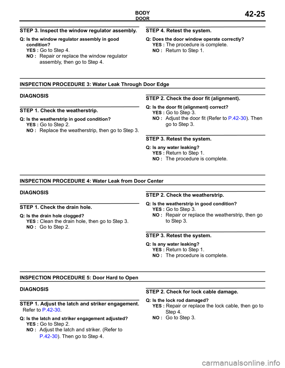
STEP 3. Inspect the window regulator assembly.
Q: Is the window regulator assembly in good
condition?
YES :
Go to Step 4.
NO : Repair or replace the window regulator
assembly, then go to Step 4.
STEP 4. Retest the system.
Q: Does the door window operate correctly?
YES :
The procedure is complete.
NO : Return to Step 1.
INSPECTION PROCEDURE 3: Water Leak Through Door Edge
DIAGNOSIS
STEP 1. Check the weatherstrip.
Q: Is the weatherstrip in good condition?
YES :
Go to Step 2.
NO : Replace the weatherstrip, then go to Step 3.
STEP 2. Check the door fit (alignment).
Q: Is the door fit (alignment) correct?
YES :
Go to Step 3.
NO : Adjust the door fit (Refer to P.42-30). Then
go to Step 3.
STEP 3. Retest the system.
Q: Is any water leaking?
YES :
Return to Step 1.
NO : The procedure is complete.
INSPECTION PROCEDURE 4: Water Leak from Door Center
DIAGNOSIS
STEP 1. Check the drain hole.
Q: Is the drain hole clogged?
YES :
Clean the drain hole, then go to Step 3.
NO : Go to Step 2.
STEP 2. Check the weatherstrip.
Q: Is the weatherstrip in good condition?
YES :
Go to Step 3.
NO : Repair or replace the weatherstrip, then go
to Step 3.
STEP 3. Retest the system.
Q: Is any water leaking?
YES :
Return to Step 1.
NO : The procedure is complete.
INSPECTION PROCEDURE 5: Door Hard to Open
DIAGNOSIS
STEP 1. Adjust the latch and striker engagement.
Refer to P.42-30.
Q: Is the latch and striker engagement adjusted?
YES :
Go to Step 2.
NO : Adjust the latch and striker. (Refer to
P.42-30). Then go to Step 4.
STEP 2. Check for lock cable damage.
Q: Is the lock rod damaged?
YES :
Repair or replace the lock cable, then go to
St e p 4.
NO : Go to Step 3.
Page 1097 of 1500

DOOR
BODY42-30
ON-VEHICLE SERVICE
DOOR FIT ADJUSTMENTM1423001100380
Required Special Tools:
MB990211: Slide Hammer
MB990243: Body Puller
MB990900 or MB991164: Door adjusting Wrench
MB990939: Brass Bar
Attach protection tape to the fender and door edges
where the hinge is installed.
Do not rotate special tool MB991164 with a torque of
over 98 N
m (72 ft-lb).
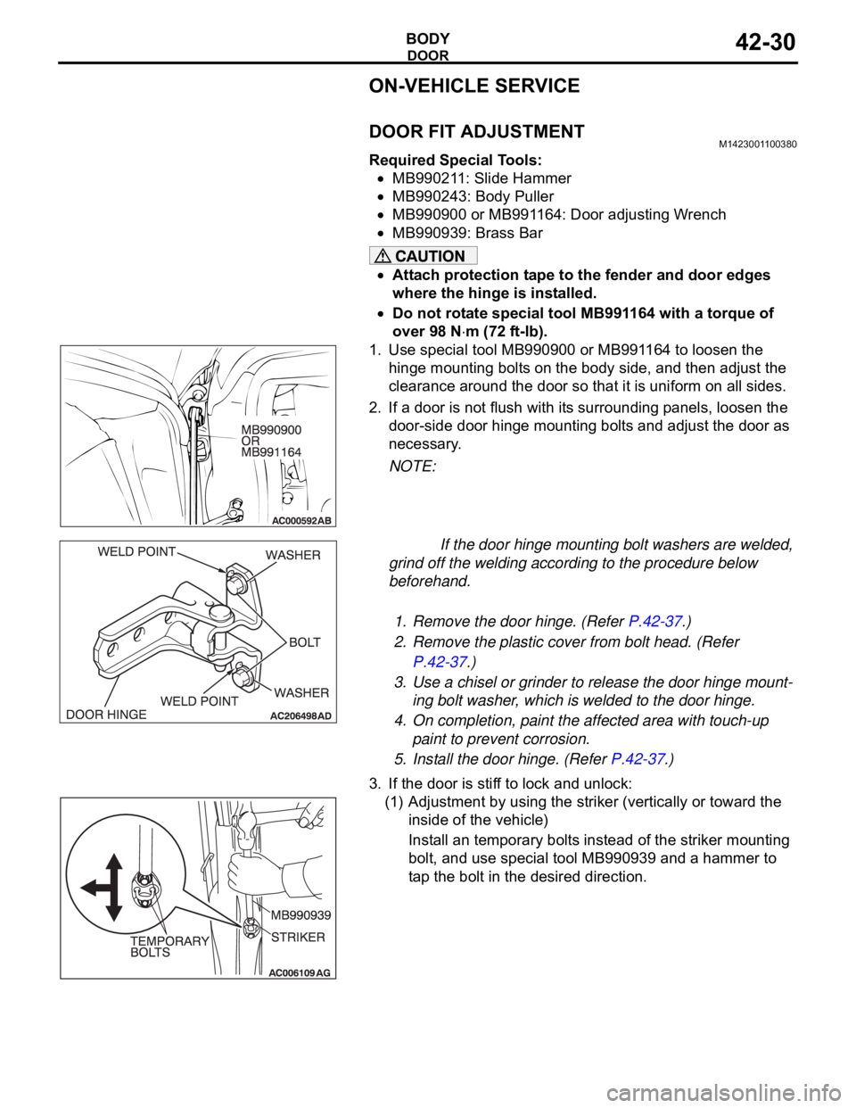
1. Use special tool MB990900 or MB991164 to loosen the
hinge mounting bolts on the body side, and then adjust the
clearance around the door so that it is uniform on all sides.
2. If a door is not flush with its surrounding panels, loosen the
door-side door hinge mounting bolts and adjust the door as
necessary.
NOTE:
If the door hinge mounting bolt washers are welded,
grind off the welding according to the procedure below
beforehand.
.
1. Remove the door hinge. (Refer P.42-37.)
2. Remove the plastic cover from bolt head. (Refer
P.42-37.)
3. Use a chisel or grinder to release the door hinge mount-
ing bolt washer, which is welded to the door hinge.
4. On completion, paint the affected area with touch-up
paint to prevent corrosion.
5. Install the door hinge. (Refer P.42-37.)
3. If the door is stiff to lock and unlock:
(1) Adjustment by using the striker (vertically or toward the
inside of the vehicle)
Install an temporary bolts instead of the striker mounting
bolt, and use special tool MB990939 and a hammer to
tap the bolt in the desired direction.
Page 1099 of 1500

DOOR
BODY42-32
GLASS SLIDING MECHANISM CHECK AND
ADJUSTMENT
M1429000900109
If the window glass automatically starts moving downwards at
the wrong time while it is being raised, carry out the following
adjustment or replacement procedures.
1. Remove the door trim assembly (Refer to GROUP 52A,
Door trim P.52A-14).
2. Remove the waterproof film (Refer to P.42-52).
Insert a cushion or similar object to prevent damage to the
glass if it should fall.
3. Remove the window regulator assembly from the door
window glass, and then raise and lower the door window
glass by hand to check the operation force.
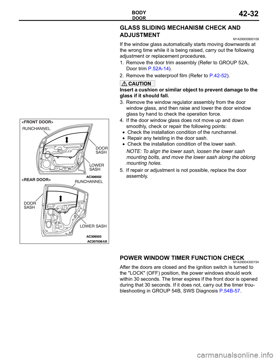
4. If the door window glass does not move up and down
smoothly, check or repair the following points:
Check the installation condition of the runchannel.
Repair any twisting in the door sash.
Check the installation condition of the lower sash.
NOTE: To align the lower sash, loosen the lower sash
mounting bolts, and move the lower sash along the oblong
mounting holes.
5. If repair or adjustment is not possible, replace the door
assembly.
POWER WINDOW TIMER FUNCTION CHECKM1429004300154
After the doors are closed and the ignition switch is turned to
the "LOCK" (OFF) position, the power windows should work
within 30 seconds. The timer expires if the front door is opened
during that 30 seconds. If it does not, carry out the timer trou-
bleshooting in GROUP 54B, SWS Diagnosis P.54B-57.