2005 MITSUBISHI 380 ignition switch cir
[x] Cancel search: ignition switch cirPage 986 of 1500

CHARGING SYSTEM
ENGINE ELECTRICAL16-9
Required Special Tool:
: Diagnostic Tool (MUT-III)
MB991824: V.C.I.
MB991827: MUT-III USB Cable
MB991910: MUT-III Main Harness A
This test determines whether the alternator outputs
normal current. For best results, use a charging sys-
tem tester. If not available, follow the steps below.
Battery posts, terminals and related acces-
sories contain lead and lead compounds.
WASH HANDS AFTER HANDLING.
1. Before the test, always be sure to check the
following.
Alternator installation
Battery (Refer to GROUP 54A, Chassis Electrical
Battery On-vehicle Service Battery Check
P.54A-5.)
NOTE: The battery to be used should be slightly
discharged. The load in a fully-charged battery
will be insufficient and the test may not be able to
be carried out correctly.
Alternator drive belt tension (Refer to GROUP 00,
General
Maintenance Service Drive Belts
(For Alternator, Power Steering Pump and Air
Conditioning) (Check) P.00-39.)
Fusible link
Abnormal noise from the alternator while the
engine is running.
2. Turn the ignition switch to the "LOCK" (OFF)
position.
3. Disconnect the negative battery cable.
Never use clips to connect the wire. Loose
connections (for example, using clips) will
lead to a serious accident because of high
current.
4. Connect a clamp-type DC test ammeter with a
range of 0
120 A to the alternator "B" terminal
output wire.
5. Connect a voltmeter with a range of 0
20 V
between the alternator "B" terminal and ground.
(Connect the positive lead of the voltmeter to the
"B" terminal, and then connect the negative lead
of the voltmeter to ground.)
6. Connect the negative battery cable.
7. Connect an engine tachometer or diagnostic tool.
8. Leave the hood open.9. Check to be sure that the reading on the voltmeter
is equal to the battery positive voltage.
NOTE: If the voltage is 0 V, the cause is probably
an open circuit in the wire or fusible link between
the alternator "B" terminal and the battery positive
terminal or malfunctioning voltmeter.
10.After turning on the headlights, start the engine.
NOTE: Because the current from the battery will
soon drop after the engine is started, step 11
should be carried out as quickly as possible in
order to obtain the maximum current output value.
11.Immediately after setting the headlights to high
beam and turning the heater blower switch to the
highest position, increase the engine speed to
2,500 r/min and read the maximum current output
value displayed on the ammeter.
Limit value: 70 % of nominal current output
NOTE: For the nominal current output, refer to the
Alternator Specifications.
NOTE: The current output value will depend on
the electrical load and the temperature of the
alternator body.
NOTE: If the electrical load is small while testing,
the specified level of current may not be output
even though the alternator is normal. In such
cases, increase the electrical load by leaving the
headlights turned on for some time to discharge
the battery or by using the lighting system in
another vehicle, and then test again.
NOTE: The specified level of current also may not
be output if the temperature of the alternator body
or the ambient temperature is too high. In such
cases, cool the alternator and then test again.
12.The reading on the ammeter should be above the
limit value. If the reading is below the limit value
and the alternator output wire is normal, remove
the alternator from the engine and check the
alternator.
13.Run the engine at idle speed after the test.
14.Turn the ignition switch to the "LOCK" (OFF)
position.
15.Disconnect the engine tachometer or diagnostic
tool.
16.Disconnect the negative battery cable.
17.Disconnect the ammeter and voltmeter .
18.Connect the negative battery cable.
19.Run the engine for 10 minutes at an idle.
Page 987 of 1500

CHARGING SYSTEM
ENGINE ELECTRICAL16-10
REGULATED VOLTAGE TESTM1161001100666
Required Special Tools:
: Diagnostic Tool (MUT-III)
MB991824: V.C.I.
MB991827: MUT-III USB Cable
MB991910: MUT-III Main Harness A
MB998467: Alternator Harness Connector
This test determines whether the voltage regulator is
correctly controlling the alternator output voltage.
Battery posts, terminals and related acces-
sories contain lead and lead compounds.
WASH HANDS AFTER HANDLING.
1. Always be sure to check the following before the
test:
Alternator installation
Check to be sure that the battery installed in the
vehicle is fully charged. (Refer to GROUP 54A,
Chassis Electrical
Battery On-vehicle Service
Battery Check P.54A-5.)
Alternator drive belt tension (Refer to GROUP 00,
General
Maintenance Service Drive Belts
(For Alternator, Power Steering Pump and Air
Conditioning) (Check) P.00-39.)
Fusible link
Abnormal noise from the alternator while the
engine is running.2. Turn the ignition switch to the "LOCK" (OFF)
position.
3. Disconnect the negative battery cable.
4. Use the special tool (Alternator harness
connector: MB998467) to connect a digital-type
voltmeter between the alternator "S" terminal and
ground. (Connect the positive lead of the
voltmeter to the "S" terminal, and then connect the
negative lead of the voltmeter to a secure ground
or to the negative battery terminal.)
5. Connect a clamp-type DC test ammeter with a
range of 0
120 A to the alternator "B" terminal
output wire.
6. Reconnect the negative battery cable.
7. Connect an engine tachometer, or diagnostic tool.
8. Turn the ignition switch to the "ON" position and
check that the reading on the voltmeter is equal to
the battery positive voltage.
NOTE: If the voltage is 0 V, the cause is probably
an open circuit in the wire or fusible link between
the alternator "S" terminal and the battery positive
terminal or malfunctioning voltmeter.
9. Check to be sure that all lights and accessories
are off.
10.Start the engine.
Page 1143 of 1500
SUNROOF ASSEMBLY
BODY42-76
SUNROOF TIMER FUNCTION CHECKM1426004300100
Keep the door closed, turn OFF the ignition switch and check to
see if the sunroof can be operated for 30 seconds after that. If
not, perform troubleshooting (Refer to GROUP 54B, SWS
Diagnosis P.54B-57).
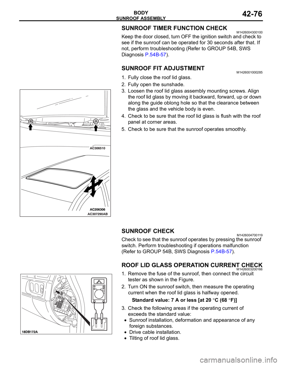
SUNROOF FIT ADJUSTMENTM1426001000285
1. Fully close the roof lid glass.
2. Fully open the sunshade.
3. Loosen the roof lid glass assembly mounting screws. Align
the roof lid glass by moving it backward, forward, up or down
along the guide oblong hole so that the clearance between
the glass and the vehicle body is even.
4. Check to be sure that the roof lid glass is flush with the roof
panel at corner areas.
5. Check to be sure that the sunroof operates smoothly.
SUNROOF CHECKM1426004700119
Check to see that the sunroof operates by pressing the sunroof
switch. Perform troubleshooting if operations malfunction
(Refer to GROUP 54B, SWS Diagnosis P.54B-57).
ROOF LID GLASS OPERATION CURRENT CHECKM1426003200166
1. Remove the fuse of the sunroof, then connect the circuit
tester as shown in the Figure.
2. Turn ON the sunroof switch, then measure the operating
current when the roof lid glass is halfway opened.
Standard value: 7 A or less [at 20
C (68 F)]
3. Check the following areas if the operating current of
exceeds the standard value:
Sunroof installation, deformation and appearance of any
foreign substances.
Drive cable installation.
Tilting of roof lid glass.
Page 1228 of 1500
HOW TO USE TROUBLESHOOTING/INSPECTION SERVICE POINTS
GENERAL00-7
HOW TO USE TROUBLESHOOTING/INSPECTION SERVICE
POINTS
TROUBLESHOOTING CONTENTSM1001013300062
During diagnosis, a DTC code associated with
other system may be set when the ignition
switch is turned on with connector(s) discon-
nected. On completion, confirm all systems
for DTC code(s). If DTC code(s) are set, erase
them all.
When the DIAGNOSTIC TOOL (MUT-III)
detects a diagnostic trouble code, its display
informs users whether a mechanical problem
currently exists (“current trouble”) or whether
it existed before but normal operation has
been restored (“past trouble”). However, if an
MPI, TPMS or SRS airbag-related DTC is set,
“Active DTC/Stored DTC” is not displayed. In
this case, follow the diagnosis procedure for
current trouble.
If a trouble, detected in a CAN communica-
tion-capable system, can be reproduced,
diagnose the CAN bus lines (Refer to GROUP
54C, Can Bus Line Diagnostics Chart
P.54C-15 or P.54C-15).
Troubleshooting of electronic control systems for
which the MUT -III can be used follows the basic out-
line described below. Even in systems for which the
MUT-III cannot be used, part of these systems still
follow this outline.
1. STANDARD FLOW OF DIAGNOSTIC
TROUBLESHOOTING
Troubleshooting strategy is shown in each group.
2. SYSTEM OPERATION AND SYMPTOM
VERIFICATION TESTS
If verification of the symptom(s) is difficult, proce-
dures for checking operation and verifying symptoms
are shown.
3. DIAGNOSTIC FUNCTION
The following trouble code diagnoses are shown.
How to read diagnostic trouble codes
How to erase diagnostic trouble codes
Input inspection service points
4. DIAGNOSTIC TROUBLE CODE CHART
If the MUT-III displays a diagnostic trouble code, find
the applicable inspection procedure according to this
chart.
5. SYMPTOM CHART
If there are symptoms, even though the MUT-III
shows that no DTCs are set, inspection procedures
for each symptom will be found by using this chart.
6. DIAGNOSTIC TROUBLE CODE
PROCEDURES
Indicates the inspection procedures corresponding to
each diagnostic trouble code. (Refer to P.00-9).
7. SYMPTOM PROCEDURES
Indicates the inspection procedures corresponding to
each symptom listed in the Symptom Chart (Refer to
P.00-9).
8. SERVICE DATA REFERENCE TABLE
Inspection items and normal judgment values have
been provided in this chart as reference information.
9. CHECK AT ECU TERMINALS
Terminal numbers for the ECU connectors, inspec-
tion items, and standard values have been provided
in this chart as reference information.
.
TERMINAL VOLTAGE CHECKS
1. Use correct tool to check each pin location on the
ENGINE-ECU Check harnes MB992044 and
measure with voltmeter.
Short-circuiting the positive (+) test probe
between a connector terminal and ground could
damage the vehicle wiring, the sensor, the ECU,
or all three. Use care to prevent this!
2. Insert the correct terminal tool into each of the
ENGINE-ECU check harness connector
terminals, and measure the voltage while referring
to the check chart.
NOTE: Measure voltage with the ECU connectors
connected.
You may find it convenient to pull out the ECU to
make it easier to connect the ENGINE-ECU check
harness.
Page 1245 of 1500
PRECAUTIONS BEFORE SERVICE
GENERAL00-24
SERVICING ELECTRICAL SYSTEMM1001011900057
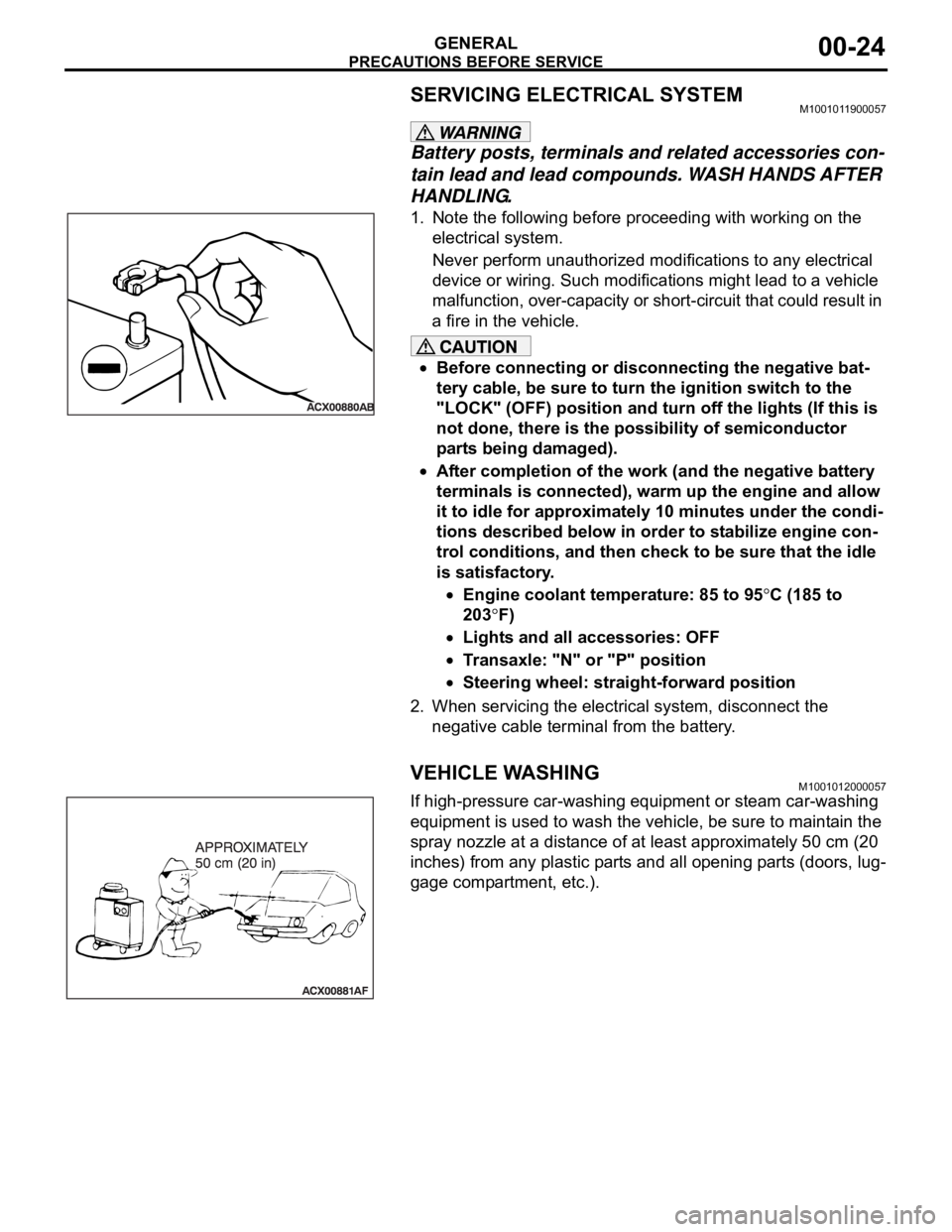
Battery posts, terminals and related accessories con-
tain lead and lead compounds. WASH HANDS AFTER
HANDLING.
1. Note the following before proceeding with working on the
electrical system.
Never perform unauthorized modifications to any electrical
device or wiring. Such modifications might lead to a vehicle
malfunction, over-capacity or short-circuit that could result in
a fire in the vehicle.
Before connecting or disconnecting the negative bat-
tery cable, be sure to turn the ignition switch to the
"LOCK" (OFF) position and turn off the lights (If this is
not done, there is the possibility of semiconductor
parts being damaged).
After completion of the work (and the negative battery
terminals is connected), warm up the engine and allow
it to idle for approximately 10 minutes under the condi-
tions described below in order to stabilize engine con-
trol conditions, and then check to be sure that the idle
is satisfactory.
Engine coolant temperature: 85 to 95C (185 to
203
F)
Lights and all accessories: OFF
Transaxle: "N" or "P" position
Steering wheel: straight-forward position
2. When servicing the electrical system, disconnect the
negative cable terminal from the battery.
VEHICLE WASHINGM1001012000057
If high-pressure car-washing equipment or steam car-washing
equipment is used to wash the vehicle, be sure to maintain the
spray nozzle at a distance of at least approximately 50 cm (20
inches) from any plastic parts and all opening parts (doors, lug-
gage compartment, etc.).
Page 1282 of 1500
TRACTION CONTROL SYSTEM (TCL) DIAGNOSIS
TRACTION CONTROL SYSTEM (TCL)13C-3
TRACTION CONTROL SYSTEM (TCL) DIAGNOSIS
INTRODUCTION TO TRACTION CONTROL SYSTEM (TCL) DIAGNOSISM1136004600026
TCL Diagnostic Trouble Code Detection
Conditions
TCL diagnostic trouble codes (TCL DTCs) are set
under different conditions, depending on the mal-
function detected. Most TCL DTCs will only be set
during vehicle operation. Some TCL DTCs will also
be set during the TCL self-check immediately after
the engine is started. When you check if an TCL DTC will be displayed again after the DTC has been
erased, you should recreate the TCL DTC set condi-
tions. Depending on the detection timing and set
conditions for the specific TCL DTC, you must either
drive the vehicle or turn the engine off and restart it.
To set the proper conditions for that DTC again, refer
to "TCL DTC SET CONDITIONS" for each TCL DTC
that you are trying to reset.
TROUBLESHOOTING STRATEGYM1136003100062
Use these steps to plan your diagnostic strategy. If
you follow them carefully, you will check most of the
possible causes of a TCL problem.
1. Gather information from the customer.
2. Verify that the condition described by the
customer exists.
3. Check the vehicle for any TCL DTC. (Refer to
P.13C-3, Diagnosis Function
How to Read and
Erase Diagnostic Trouble Codes).
4. If you can verify the condition but no TCL DTCs
are set, and the malfunction may be intermittent.
(Refer to GROUP 00, How to Use
Troubleshooting/Inspection Service Points
How
to Cope with Intermittent Malfunctions P.00-14).
5. If you can verify the condition but there is no TCL
DTCs, or the system cannot communicate with
diagnostic tool MB991958 (MUT-III sub
assembly), and find the fault. (Refer to P.13C-23,
Symptom Chart).6. If there is a TCL DTC, record the number of the
code, then erase the code from vehicle memory
using the diagnostic tool MB991958 (MUT-III sub
assembly). (Refer to P.13C-3, Diagnosis Function
How to Read and Erase Diagnostic Trouble
Codes).
7. Re-create the TCL DTC set conditions to see if
the same TCL DTC will set again. (Refer to
P.13C-3, Diagnosis Function
How to Read and
Erase Diagnostic Trouble Codes).
If the same TCL DTC sets again, perform the
diagnostic procedures for the set code. (Refer to
P.13C-8, Diagnostic Trouble Code Chart).
NOTE: If the ABS-8 ECU or the active wheel
speed sensor are disconnected, or if the wir-
ing is an open/ short circuit, the ABS 8 ECU
will shut off power supply to the respective
wheel speed sensor. All other wheel speed
sensors will operate normally. To restore the
power supply, the ignition switch must be
turned to the "OFF" position then to the "ON"
position again.
DIAGNOSIS FUNCTIONM1136003200025
HOW TO CONNECT THE DIAGNOSTIC TOOL
(MUT-III)
Required Special Tools:
MB991958: Diagnostic Tool (MUT-III Sub Assembly)
MB991824: Vehicle Communication Interface (V.C.I.)
MB991827: MUT-III USB Cable
MB991910: MUT-III Main Harness A
Page 1287 of 1500
TRACTION CONTROL SYSTEM (TCL) DIAGNOSIS
TRACTION CONTROL SYSTEM (TCL)13C-8
DIAGNOSTIC TROUBLE CODE CHARTM1136003300022
During diagnosis, a DTC associated with other
system may be set when the ignition switch is
turned on with connector(s) disconnected. On
completion, confirm all systems for DTC(s). If
DTC(s) are set, erase them all.
NOTE: If the ABS-8 ECU or the active wheel
speed sensor are disconnected, or if the wiring is
an open/ short circuit, the ABS 8 ECU will shut
off power supply to the respective wheel speed
sensor. All other wheel speed sensors will oper-
ate normally. To restore the power supply, the
ignition switch must be turned to the "OFF" posi-
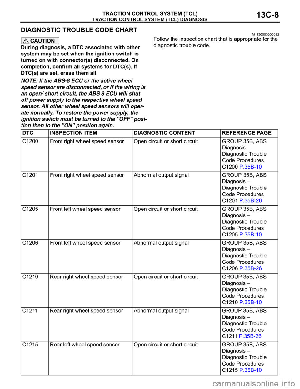
tion then to the "ON" position again.Follow the inspection chart that is appropriate for the
diagnostic trouble code.
DTC INSPECTION ITEM DIAGNOSTIC CONTENT REFERENCE PAGE
C1200 Front right wheel speed sensor Open circuit or short circuit GROUP 35B, ABS
Diagnosis
Diagnostic Trouble
Code Procedures
C1200 P.35B-10
C1201 Front right wheel speed sensor Abnormal output signal GROUP 35B, ABS
Diagnosis
Diagnostic Trouble
Code Procedures
C1201 P.35B-26
C1205 Front left wheel speed sensor Open circuit or short circuitGROUP 35B, ABS
Diagnosis
Diagnostic Trouble
Code Procedures
C1205 P.35B-10
C1206 Front left wheel speed sensor Abnormal output signal GROUP 35B, ABS
Diagnosis
Diagnostic Trouble
Code Procedures
C1206 P.35B-26
C1210 Rear right wheel speed sensor Open circuit or short circuitGROUP 35B, ABS
Diagnosis
Diagnostic Trouble
Code Procedures
C1210 P.35B-10
C1211 Rear right wheel speed sensor Abnormal output signal GROUP 35B, ABS
Diagnosis
Diagnostic Trouble
Code Procedures
C1211 P.35B-26
C1215 Rear left wheel speed sensor Open circuit or short circuit GROUP 35B, ABS
Diagnosis
Diagnostic Trouble
Code Procedures
C1215 P.35B-10
Page 1289 of 1500
TRACTION CONTROL SYSTEM (TCL) DIAGNOSIS
TRACTION CONTROL SYSTEM (TCL)13C-10
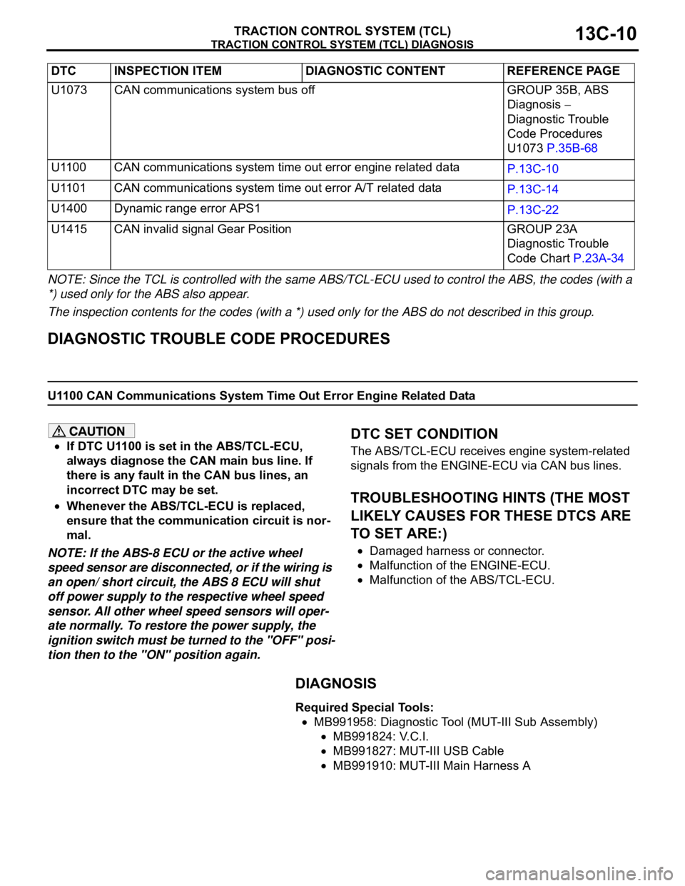
NOTE: Since the TCL is controlled with the same ABS/TCL-ECU used to control the ABS, the codes (with a
*) used only for the ABS also appear.
The inspection contents for the codes (with a *) used only for the ABS do not described in this group.
DIAGNOSTIC TROUBLE CODE PROCEDURES
U1100 CAN Communications System Time Out Error Engine Related Data
If DTC U1100 is set in the ABS/TCL-ECU,
always diagnose the CAN main bus line. If
there is any fault in the CAN bus lines, an
incorrect DTC may be set.
Whenever the ABS/TCL-ECU is replaced,
ensure that the communication circuit is nor-
mal.
NOTE: If the ABS-8 ECU or the active wheel
speed sensor are disconnected, or if the wiring is
an open/ short circuit, the ABS 8 ECU will shut
off power supply to the respective wheel speed
sensor. All other wheel speed sensors will oper-
ate normally. To restore the power supply, the
ignition switch must be turned to the "OFF" posi-
tion then to the "ON" position again.
.
DTC SET CONDITION
The ABS/TCL-ECU receives engine system-related
signals from the ENGINE-ECU via CAN bus lines.
.
TROUBLESHOOTING HINTS (THE MOST
LIKELY CAUSES FOR THESE DTCS ARE
TO SET ARE:)
Damaged harness or connector.
Malfunction of the ENGINE-ECU.
Malfunction of the ABS/TCL-ECU.
DIAGNOSIS
Required Special Tools:
MB991958: Diagnostic Tool (MUT-III Sub Assembly)
MB991824: V.C.I.
MB991827: MUT-III USB Cable
MB991910: MUT-III Main Harness A U1073 CAN communications system bus off GROUP 35B, ABS
Diagnosis
Diagnostic Trouble
Code Procedures
U1073 P.35B-68
U1100 CAN communications system time out error engine related data
P.13C-10
U1101 CAN communications system time out error A/T related data
P.13C-14
U1400 Dynamic range error APS1
P.13C-22
U1415 CAN invalid signal Gear Position GROUP 23A
Diagnostic Trouble
Code Chart P.23A-34 DTC INSPECTION ITEM DIAGNOSTIC CONTENT REFERENCE PAGE