Page 78 of 474

76 Safety and SecurityOccupant safety�
Reinstall cover after removing the
tether strap.Child seat anchors – LATCH type
This vehicle is equipped with two LATCH
(L
ower A
nchors and T
ethers for CH
ildren)
type anchors (at each of the rear seats) for
the installation of a LATCH child seat with
the matching anchor fittings.
If you have not installed a child seat, the
LATCH anchor are covered with an uphol-
stery blend.
1Indicates the position of the anchors
2Anchors
3Upholstery blend
4Installation device
�
Move rear power seats*/bench* to the
rearmost position (
�page 117).
�
Fold upholstery blend3 upward.
�
Turn installation device4 to a vertical
position so that upholstery blend3
does not fold down.
�
Install child seat according to the man-
ufacturer’s instructions.
A solid connection is established be-
tween the child seat and the body of
the vehicle.
Do not adjust rear power seat*/bench*
position after installing child restraint.
Warning!
G
Vehicles with adjustable rear seats/bench*:
Never adjust the rear seat position after in-
stalling the child restraint. Adjusting the rear
seat position after installing the child re-
straint could damage the child restraint
and/or introduce undesirable slack into the
webbing and loosen or misposition the child
restraint, lessening the effectiveness of the
child restraint and thus increasing the
chance or severity of injury in an accident.
��
Page 79 of 474

77 Safety and Security
Occupant safety
Warning!
G
Vehicles with adjustable rear seats/bench*:
Never adjust the rear seat position after in-
stalling the child restraint. Adjusting the rear
seat position after installing the child re-
straint could damage the child restraint
and/or introduce undesirable slack into the
webbing and loosen or misposition the child
restraint, lessening the effectiveness of the
child restraint and thus increasing the
chance or severity of injury in an accident.iThe child seat must be firmly attached
in the right and left side anchor fittings.
Make sure the seat belt for the center
seat can operate freely with a child
seat installed.
Non-LATCH type child seats may also
be used and can be installed using the
vehicle’s seat belt system. Install child
seat according to the manufacturer’s
instructions.
Warning!
G
Children too big for child restraint systems
must ride in back seats using regular seat
belts. Position shoulder belt across chest
and shoulder, not face or neck. A booster
seat may be necessary to achieve proper
belt positioning for children from 41 lbs until
they reach a height where a lap/shoulder
belt fits properly without a booster.
Install child seat according to manufactur-
er’s instructions.
The child seat must be firmly attached in
right and left side anchors2.
An incorrectly mounted child seat may come
loose during an accident which could result
in serious injury or death to the child.
Damaged or impact damaged child seats or
child seat mounting fittings must be re-
placed.
Do not leave children unattended in the ve-
hicle, even if the children are secured in a
child restraint system.
Page 144 of 474

142 Controls in detailInstrument clusterTachometer
The red marking on the tachometer de-
notes excessive engine speed.
To help protect the engine, the fuel supply
is interrupted if the engine is operated
within the red marking.
S 55 AMG
The tachometer of the S 55 AMG does not
have a red marking denoting excessive en-
gine speed.
To help protect the engine, the fuel supply
is interrupted if the engine is operated at
an excessive engine speed.
Outside temperature indicator
The outside temperature is displayed in
the instrument cluster (
�page 24). For in-
formation on how to select the unit of the
displayed temperature, i.e. degrees
Celsius (°C) or degrees Fahrenheit (°F),
see “Selecting temperature display mode”
(
�page 163).
The temperature sensor is located in the
front bumper area. Due to its location, the
sensor can be affected by road or engine
heat during idling or slow driving. There-
fore, the accuracy of the displayed temper-ature can only be verified by comparison to
a thermometer placed next to the sensor,
not by comparison to external displays
(e.g. bank signs, etc.).
When moving the vehicle into colder ambi-
ent temperatures (e.g. when leaving your
garage), you will notice a delay before the
lower temperature is displayed.
A delay also occurs when ambient temper-
atures rise. This prevents inaccurate tem-
perature indications caused by heat
radiated from the engine during idling or
slow driving.
Clock
The time is indicated in the instrument
cluster in the tachometer display.
You can adjust the clock using the
COMAND system. Refer to separate
COMAND operating instructions.
!Avoid driving at excessive engine
speeds, as it may result in serious en-
gine damage that is not covered by the
Mercedes-Benz Limited Warranty.
Warning!
G
The outside temperature indicator is not de-
signed to serve as an ice-warning device and
is therefore unsuitable for that purpose.
Indicated temperatures just above the freez-
ing point do not guarantee that the road sur-
face is free of ice. The road may still be icy,
especially in wooded areas or on bridges.
Page 151 of 474

149 Controls in detail
Control system
Select radio station�
Turn on the radio. Refer to separate
COMAND operating instructions.
�
Press buttonè orÿ repeatedly
until you see the currently tuned sta-
tion in the multifunction display.
1Waveband
2Station frequency
�
Press buttonk orj repeatedly
until the desired station is found.Select satellite radio* station
(USA only)
The satellite radio is treated as a radio ap-
plication.
�
Select satellite radio with the corre-
sponding key on the COMAND control
panel (SAT).
�
Press buttonè orÿ repeatedly
until you see the currently tuned sta-
tion in the multifunction display.
1SAT mode and preset number
2Channel name or number
�
Press buttonk orj repeatedly
until the desired channel is found.
iYou can only store new stations using
the corresponding feature on the radio.
Refer to separate COMAND operating
instructions.
You can also operate the radio in the
usual manner.
iAdditional optional satellite radio
equipment and a subscription to satel-
lite radio service provider are required
for satellite radio operation. Contact an
authorized Mercedes-Benz Center for
details and availability for your vehicle.
For more information, refer to separate
COMAND operating instructions.
Page 152 of 474
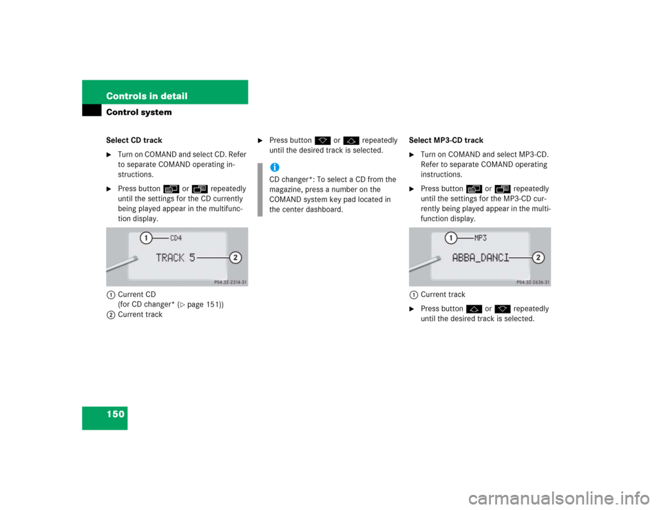
150 Controls in detailControl systemSelect CD track�
Turn on COMAND and select CD. Refer
to separate COMAND operating in-
structions.
�
Press buttonè orÿ repeatedly
until the settings for the CD currently
being played appear in the multifunc-
tion display.
1Current CD
(for CD changer* (
�page 151))
2Current track
�
Press buttonk orj repeatedly
until the desired track is selected.Select MP3-CD track
�
Turn on COMAND and select MP3-CD.
Refer to separate COMAND operating
instructions.
�
Press buttonè orÿ repeatedly
until the settings for the MP3-CD cur-
rently being played appear in the multi-
function display.
1Current track
�
Press buttonj ork repeatedly
until the desired track is selected.
iCD changer*: To select a CD from the
magazine, press a number on the
COMAND system key pad located in
the center dashboard.
Page 153 of 474

151 Controls in detail
Control system
CD changer* operating mode
General notes
Should excessively high temperatures oc-
cur while in CD mode,
CD TEMP HIGH
will
appear on the multifunction display and
muting will take place. The unit will then
switch back to the last operating mode
used until the temperature has decreased
to a safe operating level.
Should excessively low temperatures oc-
cur while in CD mode,
CD TEMP LOW
will ap-
pear on the multifunction display, but the
CD will continue to play.
Handle CDs carefully to prevent interfer-
ence during playback. Avoid fingerprints
and dust on CDs. Do not write on CDs or
apply any label or other material to them.
Only use original CDs. Using copied CDs
may create problems during playback.Clean CDs from time to time with a com-
mercially available cleaning cloth. No sol-
vents, anti-static sprays, etc. should be
used for cleaning. Replace the CD in its
case after use. Protect CDs from heat and
direct sunlight.
Only use CDs, which bear the label shown
and that conform to the compact disc dig-
ital audio standard (IEC 60908).
Use of CDs which do not meet this stan-
dard may cause damage to the CD chang-
er. Do not play single-CDs (80 mm) with an
adapter.For information on operating the CD
changer, refer to separate COMAND oper-
ating instructions.
!Your CD drive has been designed to
play CDs which correspond to the IEC
60908 standard.
If you insert thicker data carriers,
e.g. ones that have data on both sides
(one side with DVD data, the other side
with audio data), they cannot be eject-
ed and will damage the drive.
Page 157 of 474

155 Controls in detail
Control system
�
Press buttons.
The system dials the selected phone
number.�
If the connection is successful, the
name of the party you called and
the duration of the call will appear
in the display.
�
If no connection is made, the con-
trol system stores the dialed num-
ber in the redial memory.Redialing
The control system stores the most recent-
ly dialed phone numbers. This eliminates
the need to search through your entire
phone book.
�
Press buttonÿ orè repeatedly
until you see the
TEL
menu in the dis-
play.
�
Press buttons.
In the display you see the first number
in the redial memory.
�
Press buttonj ork repeatedly
until the desired name appears in the
display.
�
Press buttons.
The control system dials the selected
phone number.
NAVI menu
In the
NAVI
menu, you will see which status
the navigation system has.
�
Press buttonè orÿ repeatedly
until you see the message
NAVI
in the
display.
�
If the navigation system is switched off,
the message
NAVI OFF
is shown in the
display.
�
If the navigation system is on and no
destination has been entered, you will
see the current direction in which the
vehicle is moving and the names of
streets in the display.
Please refer to separate COMAND operat-
ing instructions on how to activate the
route guidance system.
iIf you do not want to use the telephone,
press buttont.
Page 164 of 474
162 Controls in detailControl systemThe table below shows what settings can
be changed within the various menus. De-
tailed instructions on making individual
settings can be found on the following pag-
es.INSTRUMENT CLUSTER
LIGHTING
VEHICLE
CONVENIENCE
Select temperature display
mode
Set daytime running lamp mode
(USA only)
Set automatic locking
Set key-dependency
Select multifunction display
mode
Set locator lighting
Limiting opening height of trunk
lid*
Activate easy-entry/exit feature
Select language
Exterior lamps delayed shut-off
Set parking position for exterior
rear view mirror
Select tire inflation pressure
unit
Interior lighting delayed shut-off
Set fold-in function for exterior
rear view mirrorsAdjusting the drive-dynamic
seat