Page 415 of 498
.
Vehicles with Minispare wheel:
�
Take the wheel wrench, the wheel
bolts, an")
413 Practical hints
Flat tire
Mounting the spare wheel
Preparing the vehicle
Prepare the vehicle as described
(�page 412).
Vehicles with Minispare wheel:
�
Take the wheel wrench, the wheel
bolts, and the jack out of the trunk
(�page 389).
�
Take the Minispare wheel out of the
trunk (
�page 393).
Vehicles with collapsible tire
(CLK 55 AMG only):
�
Take the collapsible tire, wheel wrench,
wheel bolts, jack, and electric air pump
out of the trunk (
�page 390).Lifting the vehicle
�
Prevent the vehicle from rolling away
by blocking wheels with wheel chocks
or other sizable objects.
One wheel chock is included with the
vehicle tool kit (
�page 389).
When changing wheel on a level surface:
�
Place the wheel chock in front of and
another sizable object behind the
wheel that is diagonally opposite to the
wheel being changed.
When changing wheel on a hill:
�
Place the wheel chock and another
sizable object on the downhill side
blocking both wheels of the other axle.
Warning!
G
The jack is designed exclusively for jacking
up the vehicle at the jack take-up brackets
built into both sides of the vehicle. To help
avoid personal injury, use the jack only to lift
the vehicle during a wheel change. Never
get beneath the vehicle while it is supported
by the jack. Keep hands and feet away from
the area under the lifted vehicle. Always
firmly set parking brake and block wheels
before raising vehicle with jack.
Do not disengage parking brake while the
vehicle is raised. Be certain that the jack is
always vertical (plumb line) when in use,
especially on hills. Always try to use the jack
on level surface. Make sure the jack arm is
fully seated in the jack take-up bracket. Al-
ways lower the vehicle onto sufficient ca-
pacity jackstands before working under the
vehicle.
Page 420 of 498

418 Practical hintsFlat tire�
Detach the electric air pump.
�
Store the electrical plug and the air
hose behind the flap and place the
electric air pump back in the trunk.Lowering the vehicle
�
Lower vehicle by turning crank
counterclockwise until vehicle is
resting fully on its own weight.
�
Remove the jack.1 - 5Wheel bolts
�
Tighten the five wheel bolts evenly,
following the diagonal sequence
illustrated (1to5), until all bolts are
tight. Observe a tightening torque
of 80 lb-ft (110 Nm).
Warning!
G
Follow recommend inflation pressures.
Do not overinflate tires. Overinflating tires
can result in sudden deflation (blowout) be-
cause they are more likely to become punc-
tured or damaged by road debris, potholes,
etc.
Do not underinflate tires. Underinflated tires
wear unevenly, adversely affect handling
and fuel economy, and are more likely to fail
from being overheated.
Warning!
G
Vehicles with collapsible tire
(CLK 55 AMG only):
Inflate collapsible tire only after the wheel is
properly mounted.
Inflate the collapsible tire using the electric
pump (
�page 416) before
lowering the ve-
hicle.
��
Page 423 of 498
421 Practical hints
Battery
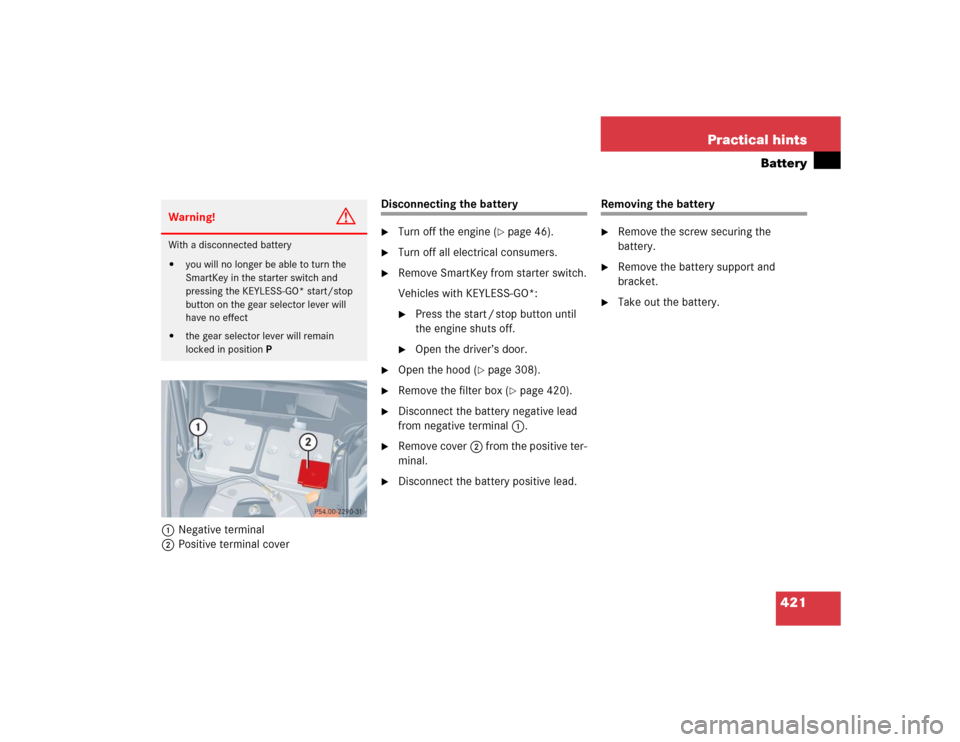
1Negative terminal
2Positive terminal cover
Disconnecting the battery�
Turn off the engine (
�page 46).
�
Turn off all electrical consumers.
�
Remove SmartKey from starter switch.
Vehicles with KEYLESS-GO*:�
Press the start / stop button until
the engine shuts off.
�
Open the driver’s door.
�
Open the hood (
�page 308).
�
Remove the filter box (
�page 420).
�
Disconnect the battery negative lead
from negative terminal1.
�
Remove cover2 from the positive ter-
minal.
�
Disconnect the battery positive lead.
Removing the battery�
Remove the screw securing the
battery.
�
Remove the battery support and
bracket.
�
Take out the battery.
Warning!
G
With a disconnected battery�
you will no longer be able to turn the
SmartKey in the starter switch and
pressing the KEYLESS-GO* start/stop
button on the gear selector lever will
have no effect
�
the gear selector lever will remain
locked in positionP
Page 424 of 498

422 Practical hintsBatteryCharging and reinstalling battery�
Charge battery in accordance with the
instructions of the battery charger
manufacturer.
�
Reinstall the charged battery. Follow
the previously described steps in
reverse order.
Reconnecting the battery�
Turn off all electrical consumers.
�
Remove SmartKey from starter switch.
Vehicles with KEYLESS-GO*:�
Press the start / stop button until
the engine shuts off.
�
Open the driver’s door.
�
Connect the battery positive lead and
fasten its cover 2.
�
Connect the battery negative lead.
�
Reinstall the filter box (
�page 420).Batteries contain materials that can harm
the environment if disposed of improperly.
Large 12-volt storage batteries contain
lead. Recycling of batteries is the preferred
method of disposal. Many states require
sellers of batteries to accept old batteries
for recycling.
Warning!
G
Never charge a battery while still installed in
the vehicle. Gases may escape during charg-
ing and cause explosions that may result in
paint damage, corrosion or personal injury.
!NEVER invert the terminal connections!!The battery, its filler caps and the vent
tube must always be securely installed
when the vehicle is in operation.
iThe following procedures must be car-
ried out following any interruption of
battery power (e.g. due to reconnect-
ing):�
Set the clock (
�page 151) (vehi-
cles with COMAND*: see COMAND
operator’s manual).
�
Resynchronize the side windows
(�page 250).
�
Resynchronize the tilt/sliding
sunroof* (
�page 254).
Page 427 of 498

425 Practical hints
Towing the vehicle
�Towing the vehicle
Towing the vehicle
Mercedes-Benz recommends that the vehi-
cle be transported with all wheels off the
ground using flatbed or appropriate wheel
lift/dolly equipment.When circumstances do not permit the
recommended towing methods, the vehi-
cle may be towed with all wheels on the
ground or front wheels raised only so far as
necessary to have the vehicle moved to a
safe location where the recommended
towing methods can be employed.
!Use flatbed or wheel lift/dolly equip-
ment with SmartKey in starter switch
turned to position0.
Do not tow with sling-type equipment.
Towing with sling-type equipment over
bumpy roads will damage radiator and
supports.
To prevent damage during transport,
do not tie down vehicle by its chassis or
suspension parts.
Switch off the tow-away alarm
(�page 91) and the automatic central
locking (
�page 158).
!If the vehicle is towed with the front
axle raised, the engine must be shut off
(SmartKey in starter switch position0
or1). Otherwise, the ESP will immedi-
ately be engaged and will apply the rear
wheel brakes.
When towing the vehicle with all wheels
on the ground, the selector lever must
be in positionN and the SmartKey
must be in starter switch position2.
When towing the vehicle with all wheels
on the ground or the front axle raised,
the vehicle may be towed only for dis-
tances up to 30 miles (50 km) and at a
speed not to exceed 30 mph
(50 km/h).
!To be certain to avoid a possibility of
damage to the transmission, however,
we recommend the drive shaft be dis-
connected at the rear axle drive flange
for any towing beyond a short tow to a
nearby garage.
Page 428 of 498

426 Practical hintsTowing the vehicleWarning!
G
Prior to towing the vehicle with all wheels on
the ground, make certain that the SmartKey
is in starter switch position
2.
If the SmartKey is left in starter switch posi-
tion
0 for an extended period of time, it can
no longer be turned in the switch. In this
case, the steering is locked. To unlock, re-
move SmartKey from starter switch and re-
insert.
If circumstances require towing the vehicle
with all wheels on the ground, always tow
with a tow bar if:
�
the engine will not run
�
there is a malfunction in the power sup-
ply or in the vehicle’s electrical system
as that will be necessary to adequately con-
trol the towed vehicle.
Warning!
G
With the engine not running, there is no
power assistance for the brake and steering
systems. In this case, it is important to keep
in mind that a considerably higher degree of
effort is necessary to brake and steer the ve-
hicle. Adapt your driving accordingly.iTo signal turns while being towed with
the hazard warning flasher in use,
switch on ignition and activate the
combination switch for the left or right
turn signal in the usual manner – only
the selected turn signal will operate.
Upon canceling the turn signal, the haz-
ard warning flasher will operate again.
!When towing the vehicle with all wheels
on the ground, please note the follow-
ing:
With the automatic central locking acti-
vated and the SmartKey in starter
switch position2, or KEYLESS-GO*
start/stop button in position2, the ve-
hicle doors lock if the left front wheel
as well as the right rear wheel are turn-
ing at vehicle speeds of approx. 9 mph
(15 km / h) or more.
Switch off the tow-away alarm
(�page 91).
To prevent the vehicle door locks from
locking, deactivate the automatic cen-
tral locking (
�page 158).
Towing of the vehicle should only be
done using the properly installed tow-
ing eye bolt. Never attach tow cable,
tow rope or tow rod to the vehicle chas-
sis, frame or suspension parts.
Page 429 of 498
427 Practical hints
Towing the vehicle
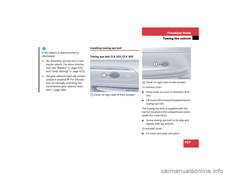
Installing towing eye bolt
Towing eye bolt CLK 320/CLK 500
1Cover on right side of front bumper2Cover on right side of rear bumper
To remove cover:
�
Press mark on cover in direction of ar-
row.
�
L i f t c o v e r o f f t o r e v e a l t h r e a d e d h o l e f o r
towing eye bolt.
The towing eye bolt is supplied with the
tool kit (located in the compartment under-
neath the trunk floor).
�
Screw towing eye bolt to its stop and
tighten with lug wrench.
To reinstall cover:
�
Fit cover and snap into place.
iIf the battery is disconnected or
discharged�
the SmartKey will not turn in the
starter switch. For more informa-
tion, see “Battery” (
�page 420)
and “Jump starting” (�page 423).
�
the gear selector lever will remain
locked in positionP. For informa-
tion on manually unlocking the
transmission gear selector lever
see (
�page 400).
Page 433 of 498
431 Practical hintsFuses
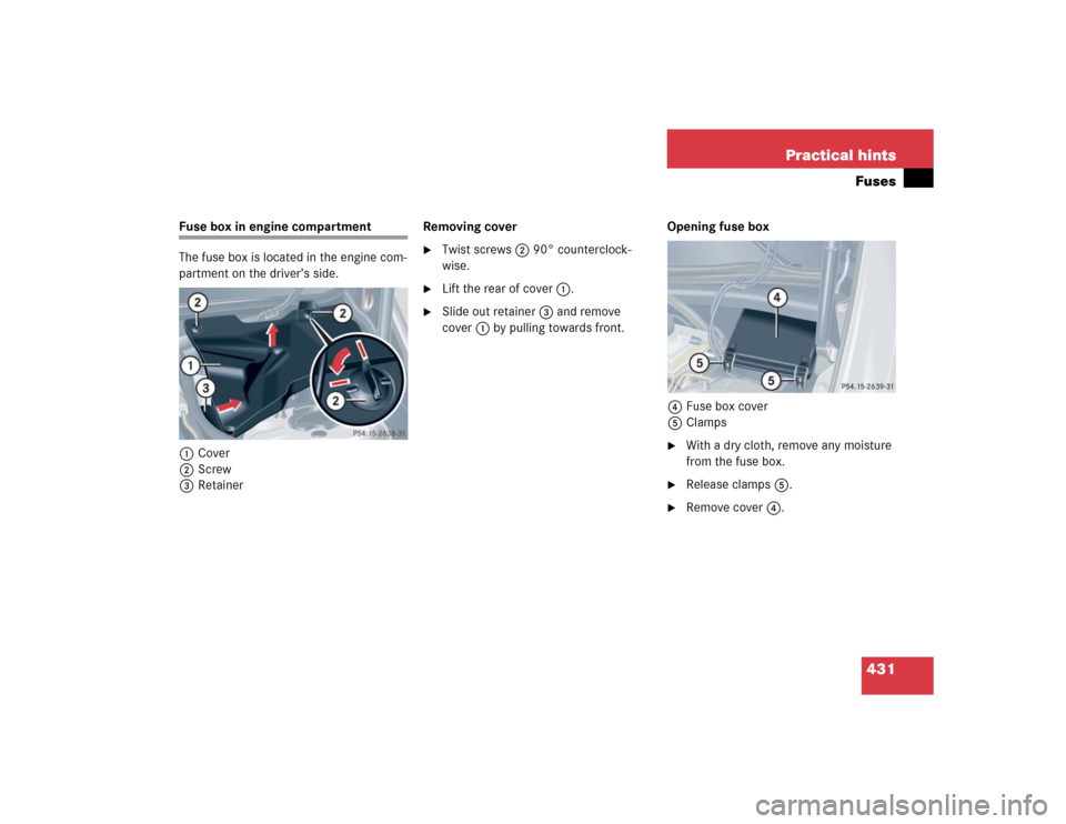
Fuse box in engine compartment
The fuse box is located in the engine com-
partment on the driver’s side.
1Cover
2Screw
3RetainerRemoving cover
�
Twist screws2 90° counterclock-
wise.
�
Lift the rear of cover1.
�
Slide out retainer3 and remove
cover1 by pulling towards front.Opening fuse box
4Fuse box cover
5Clamps
�
With a dry cloth, remove any moisture
from the fuse box.
�
Release clamps5.
�
Remove cover4.