Page 251 of 498
 w")
249 Controls in detail
Power windows
Stopping windows�
Press or pull respective switch again.
Opening and closing the windows with
the SmartKey
The power tilt/sliding sunroof*
(
�p a g e 2 5 1 ) w i l l a l s o b e o p e n e d o r c l o s e d
when the power windows are operated
with the SmartKey.
�
Aim transmitter eye at the driver’s door
handle.
!If the upward movement of a door win-
dow is blocked during the closing pro-
cedure, the door window will stop and
open slightly.
Remove the obstruction, pull the
switch again past the resistance point
and release.
If the door window still does not close
when there is no obstruction, then pull
the switch and hold it. The door window
will then close without the obstruction
sensor function.Warning!
G
Driver’s door only:
If within five seconds you again pull the
switch past the resistance point and re-
lease, the automatic reversal will not
function.
Warning!
G
Never operate the windows or tilt/sliding
sunroof* if there is the possibility of anyone
being harmed by the opening or closing pro-
cedure.
In the event that the procedure causes
potential danger, the procedure can be
immediately halted by releasing the button
on the SmartKey. To reverse direction of
movement, press Œ for opening or ‹
for closing.
Page 254 of 498
.
Opening and closing the power
tilt/sliding sunroof
�
To open, close, raise, or lower the
tilt/sliding sunroof, mov")
252 Controls in detailPower tilt/sliding sunroof*
�
Switch on ignition (
�page 36).
Opening and closing the power
tilt/sliding sunroof
�
To open, close, raise, or lower the
tilt/sliding sunroof, move the sunroof
switch to resistance point in the
required direction of arrows1 to4.
Release the sunroof switch when the
tilt/sliding sunroof has reached the
desired position.Fully opening (Express-open) and
closing (Express-close) the power
tilt/sliding sunroof
�
To open or close the tilt/sliding
sunroof, move the sunroof switch past
the resistance point in the required
direction of arrow3 or4 and
release.
The tilt/sliding sunroof opens or closes
completely.
Stopping the power tilt/sliding sunroof
during Express-operation
�
Move the sunroof switch in any
direction.
When leaving the vehicle, always remove the
SmartKey or SmartKey with KEYLESS-GO*
from the starter switch, take it with you, and
lock the vehicle. Do not leave children
unattended in the vehicle, or with access to
an unlocked vehicle. Unsupervised use of
vehicle equipment can cause an accident
and/or serious personal injury.!To avoid damaging the seals, do not
transport any objects with sharp edges
which can stick out of the tilt/sliding
sunroof.
Do not open the tilt/sliding sunroof if
there is snow or ice on the roof, as this
could result in malfunctions.
The tilt/sliding sunroof can be opened
or closed manually should an electrical
malfunction occur (
�page 401).
iYou can also open or close the tilt/slid-
ing sunroof using the:�
SmartKey (summer opening/con-
venience feature) (
�page 249)
�
button, in the control panel of
the climate control (
�page 185) or
automatic climate control
(
�page 195)
�
buttone in the control panel of
the automatic climate control
(�page 195)
iIf the movement of the tilt/sliding
sunroof is blocked during the closing
procedure, the tilt/sliding sunroof will
stop and re-open slightly.
��
Page 264 of 498

262 Controls in detailDriving systemsWarning indicators
Visual signals indicate to the driver the rel-
ative distance between the sensors and an
obstacle. The warning indicator for the
front area is located above the center air
vents in the dashboard. The warning indi-
cator for the rear area is integrated in the
rear dome lighting.
1Left side of the vehicle
2Right side of the vehicle
Each warning indicator is divided into six
yellow and two red distance segments for
either side of the vehicle. The Parktronic
system is ready when the border around
the indicator is illuminated.The position of the gear selector lever de-
termines which warning indicators will be
activated.As your vehicle approaches an object, one
or more distance segments will illuminate,
depending on the distance. When the
eighth distance segment illuminates, you
have reached the minimum distance.
�
Front area: An intermittent acoustic
warning will sound as the first red dis-
tance segment illuminates and a con-
stant acoustic warning lasting a
maximum of two seconds will sound for
the second red distance segment. The
signal is canceled when the gear selec-
tor lever is placed in positionP.
�
Rear area: An intermittent acoustic
warning will sound as the first red dis-
tance segment illuminates and a con-
stant acoustic warning lasting a
maximum of two seconds will sound for
the second red distance segment. The
signal is canceled when the gear selec-
tor lever is placed in position DorP.
Gear selector le-
ver position
Warning indicator
D
Front area activated
R or N
Front and rear area
activated
P
Neither activated
Page 276 of 498
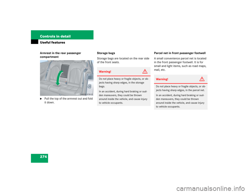
274 Controls in detailUseful featuresArmrest in the rear passenger
compartment�
Pull the top of the armrest out and fold
it down.Storage bags
Storage bags are located on the rear side
of the front seats.Parcel net in front passenger footwell
A small convenience parcel net is located
in the front passenger footwell. It is for
small and light items, such as road maps,
mail, etc.
Warning!
G
Do not place heavy or fragile objects, or ob-
jects having sharp edges, in the storage
bags.
In an accident, during hard braking or sud-
den maneuvers, they could be thrown
around inside the vehicle, and cause injury
to vehicle occupants.
Warning!
G
Do not place heavy or fragile objects, or ob-
jects having sharp edges, in the parcel net.
In an accident, during hard braking or sud-
den maneuvers, they could be thrown
around inside the vehicle, and cause injury
to vehicle occupants.
Page 277 of 498

275 Controls in detail
Useful features
Cup holders Cup holder in the dashboard
1Cover
Opening cup holder
�
Push cover1.
The cup holder opens automatically.
Closing cup holder
�
Push the cup holder back until it
engages.Cup holder in rear seat armrest
Opening cup holder
�
Briefly press the front of cup holder.
The cup holder slides out slightly.
�
Pull out the cup holder until it stops.
Closing cup holder
�
Slide cup holder back in direction of
arrow1 until it engages.
Warning!
G
In order to help prevent spilling liquids on
vehicle occupants, only use containers that
fit into the cup holder. Use lids on open
containers and do not fill containers to a
height where the contents, especially hot
liquids, could spill during braking, vehicle
maneuvers, or in an accident.
When not in use, keep the cup holder
closed. An open cup holder may cause injury
to you and others when contacted during
braking, vehicle maneuvers, or in an
accident.
Keep in mind that objects placed in cup
holder may come loose during braking,
vehicle maneuvers, or in an accident and be
thrown around in the vehicle interior.
Objects thrown around in the vehicle
interior may cause an accident and/or
serious personal injury.
Page 279 of 498

277 Controls in detail
Useful features
Opening ashtray�
Pull at top of cover3.
Removing ashtray insert
�
Push button1 to disengage ashtray
insert2 and remove it.
Reinstalling ashtray insert
�
Push the ashtray insert2 down into
the retainer until it engages.
�
Push at top of cover3 to close
ashtray.
Cigarette lighter
1Cover
2Cigarette lighter�
Switch on ignition (
�page 36).
�
Briefly press the bottom of cover
plate1.
The cover plate opens automatically.
�
Push in cigarette lighter2.
The cigarette lighter will pop out
automatically when hot.
�
Push down cover plate 1 to close the
ashtray.
The cover plate engages.Warning!
G
Never touch the heating element or sides of
the lighter; they are extremely hot. Hold the
knob only.
When leaving the vehicle, always remove the
SmartKey or SmartKey with KEYLESS-GO*
from the starter switch, take it with you, and
lock the vehicle. Do not leave children unat-
tended in the vehicle, or with access to an
unlocked vehicle. Unsupervised use of vehi-
cle equipment may cause an accident
and/or serious personal injury.iThe lighter socket can be used to ac-
commodate electrical accessories up
to a maximum 85 W.
Page 280 of 498
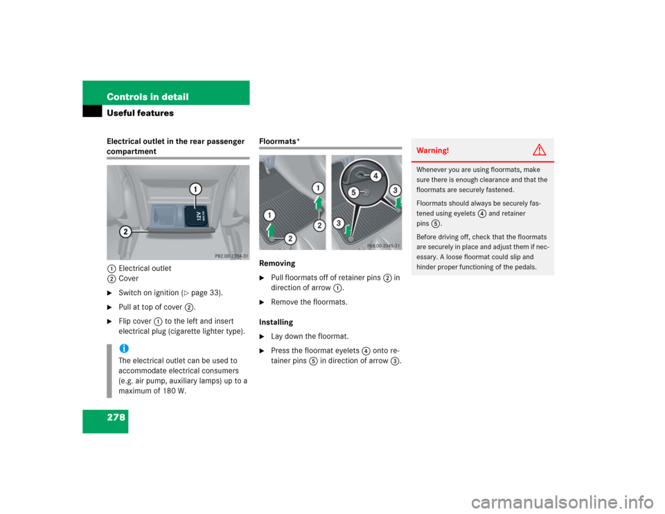
278 Controls in detailUseful featuresElectrical outlet in the rear passenger compartment
1Electrical outlet
2Cover�
Switch on ignition (
�page 33).
�
Pull at top of cover2.
�
Flip cover1 to the left and insert
electrical plug (cigarette lighter type).
Floormats*
Removing�
Pull floormats off of retainer pins2 in
direction of arrow1.
�
Remove the floormats.
Installing
�
Lay down the floormat.
�
Press the floormat eyelets4 onto re-
tainer pins5 in direction of arrow3.
iThe electrical outlet can be used to
accommodate electrical consumers
(e.g. air pump, auxiliary lamps) up to a
maximum of 180 W.
Warning!
G
Whenever you are using floormats, make
sure there is enough clearance and that the
floormats are securely fastened.
Floormats should always be securely fas-
tened using eyelets
4
and retainer
pins
5
.
Before driving off, check that the floormats
are securely in place and adjust them if nec-
essary. A loose floormat could slip and
hinder proper functioning of the pedals.
Page 292 of 498

290 Controls in detailUseful featuresStep 7:�
To program the remaining two buttons,
repeat the steps above starting with
step 3.Rolling code programming
To train a garage door opener (or other roll-
ing code devices) with the rolling code fea-
ture, follow these instructions after
completing the “Programming” portion
(steps 1 through 6) of this text. (A second
person may make the following training
procedures quicker and easier.)
Step 8:
�
Locate “training” button on the garage
door opener motor head unit.
Exact location and color of the button
may vary by garage door opener brand.
Depending on manufacturer, the “train-
ing” button may also be referred to as
“learn”or “smart” button. If there is dif-
ficulty locating the transmitting button,
refer to the garage door opener
operator’s manual. Step 9:
�
Press “training” button on the garage
door opener motor head unit.
The “training light” is activated.
You have 30 seconds to initiate the
following step.
Step 10:
�
Firmly press, hold for two seconds and
release the programmed integrated
signal transmitter button (2, 3
or4).
Step 11:
�
Press, hold for two seconds and re-
lease same button a second time to
complete the training process.
Some garage door openers (or other rolling
code equipped devices) may require you to
perform this procedure a third time to
complete the training.
iIf the indicator lamp1 blinks rapidly
for about two seconds and then turns
to a constant light, continue with pro-
gramming steps 8 through 12 as your
garage door opener may be equipped
with the “rolling code” feature.