Page 394 of 474

393
Practical hints
Replacing wiper blades
� Replacing wiper blades
Removing�
Remove SmartKey from starter switch.
�
Fold wiper arm forward.
1 Unlock
2 Lock
�
Pull the tab in the direction of arrow 1
and remove windshield wiper.
Installing�
Slide the wiper blade into the cutout on
the wiper arm (see arrows).
�
Slide the tab back in the direction of
arrow 2 until it audibly engages.
�
Fold the wiper arm back to rest on the
windshield.
Warning!
G
For safety reasons, remove SmartKey from
starter switch before replacing a wiper
blade, otherwise the motor could suddenly
turn on and cause injury.
!Never open the hood when the wiper
arm is folded forward.
Hold onto the wiper when folding the
wiper arm back. If released, the force
of the impact from the tensioning
spring could crack the windshield.
Do not allow the wiper arms to contact
the windshield glass without a wiper
blade inserted.
Make certain that the wiper blades are
properly installed. Improperly installed
wiper blades may cause windshield
damage.
For your convenience, we recommend
that you have this work carried out by
an authorized Mercedes-Benz Center.
Page 396 of 474

395
Practical hints
Flat tire
Lifting the vehicle�
Prevent the vehicle from rolling away
by blocking wheels with wheel chocks
or other sizable objects.
One wheel chock is included with
vehicle tool kit (
�page 373).
When changing wheel on a level surface:
�
Place the wheel chock (located in the
vehicle tool kit) in front of and another
sizable object behind the wheel that is
diagonally opposite to the wheel being
changed.
When changing wheel on a hill:
�
Place the wheel chock and other size-
able object on the downhill side block-
ing both wheels of the other axle.
�
Take the two-piece wheel wrench and
the jack out of the vehicle tool kit
(�page 373). Assemble wheel wrench.
�
On wheel to be changed, loosen but do
not yet remove the wheel bolts
(approximately one full turn with
wrench).
Warning!
G
The jack is designed exclusively for jacking
up the vehicle at the jack take-up brackets
built into both sides of the vehicle. To help
avoid personal injury, use the jack only to lift
the vehicle during a wheel change. Never
get beneath the vehicle while it is supported
by the jack. Keep hands and feet away from
the area under the lifted vehicle. Always
firmly set parking brake and block wheels
before raising vehicle with jack.
Do not disengage parking brake while the
vehicle is raised. Be certain that the jack is
always vertical (plumb line) when in use, es-
pecially on hills. Always try to use the jack
on level surface. Make sure the jack arm is
fully seated in the jack take-up bracket.
Always lower the vehicle onto sufficient
capacity jackstands before working under
the vehicle.
Page 401 of 474
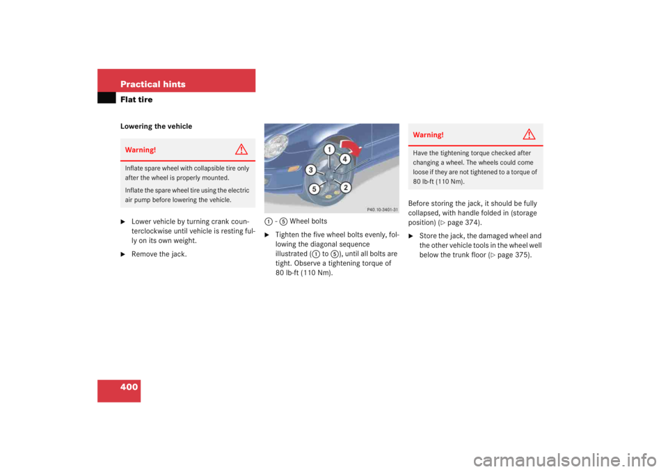
400 Practical hintsFlat tireLowering the vehicle�
Lower vehicle by turning crank coun-
terclockwise until vehicle is resting ful-
ly on its own weight.
�
Remove the jack.1
-5 Wheel bolts
�
Tighten the five wheel bolts evenly, fol-
lowing the diagonal sequence
illustrated ( 1 to 5 ), until all bolts are
tight. Observe a tightening torque of
80 lb-ft (110 Nm). Before storing the jack, it should be fully
collapsed, with handle folded in (storage
position) (
�page 374).
�
Store the jack, the damaged wheel and
the other vehicle tools in the wheel well
below the trunk floor (
�page 375).
Warning!
G
Inflate spare wheel with collapsible tire only
after the wheel is properly mounted.
Inflate the spare wheel tire using the electric
air pump before lowering the vehicle.
Warning!
G
Have the tightening torque checked after
changing a wheel. The wheels could come
loose if they are not tightened to a torque of
80 lb-ft (110 Nm).
Page 403 of 474
.
�
Turn off all electrical consumers.
�
Remove SmartKey from starter s")
402 Practical hintsBattery1Negative terminal
2 Positive terminal cover
Disconnecting the battery�
Turn off the engine (
�page 58).
�
Turn off all electrical consumers.
�
Remove SmartKey from starter switch.
�
Open the hood (
�page 291).
�
Read and observe safety instructions
and precautions (
�page 297).
�
Remove the filter box (
�page 401).
�
Disconnect battery negative lead from
negative terminal 1.
�
Remove cover 2 from the positive
terminal.
�
Disconnect the battery positive lead.
Removing the battery�
Remove the screw-nuts securing the
battery.
�
Remove the battery bracket.
�
Take out the battery.
Charging and reinstalling battery�
Charge battery in accordance with the
instructions of the battery charger
manufacturer.
�
Reinstall the charged battery. Follow
the previously described steps in re-
verse order.
Warning!
G
With a disconnected battery�
you will no longer be able to turn the
SmartKey in the starter switch
�
the gear selector lever will remain
locked in position P
��
Page 404 of 474
.
�")
403
Practical hints
Battery
Reconnecting the battery�
Turn off all electrical consumers.
�
Remove SmartKey from the starter
switch.
�
Connect the positive lead and fasten its
cover
2 (
�page 402).
�
Connect the negative lead.
�
Reinstall the filter box (
�page 401).
Batteries contain materials that can harm
the environment if disposed of improperly.
Large 12-volt storage batteries contain
lead. Recycling of batteries is the preferred
method of disposal. Many states require
sellers of batteries to accept old batteries
for recycling.
Warning!
G
Never charge a battery while still installed in
the vehicle unless the accessory battery
charge unit approved by Mercedes-Benz is
being used. Gases may escape during charg-
ing and cause explosions that may result in
paint damage, corrosion or personal injury.
An accessory battery charge unit specially
adapted for Mercedes-Benz vehicles and
tested and approved by Mercedes-Benz is
available, permitting the charging of the bat-
tery in its installed position. Contact an au-
thorized Mercedes-Benz Center for
information and availability. Charge battery
in accordance with the instructions for the
accessory battery charger.
!NEVER invert the terminal connections!!The battery, its filler caps and the vent
tube must always be securely installed
when the vehicle is in operation.
iThe following procedures must be car-
ried out following any interruption of
battery power (e.g. due to reconnec-
tion):�
Set the clock (
�page 139) (vehi-
cles with COMAND*: see COMAND
operator’s manual).
�
Resynchronize side windows
(�page 240).
�
Resynchronize panorama roof with
power tilt/sliding panel*
(�page 246).
Page 407 of 474

406 Practical hintsTowing the vehicleMercedes-Benz recommends that the vehi-
cle be transported with all wheels off the
ground using flatbed or appropriate wheel
lift/dolly equipment. This method is pref-
erable to other types of towing.When circumstances do not permit the
recommended towing methods, the vehi-
cle may be towed with all wheels on the
ground or front wheels raised only so far as
necessary to have the vehicle moved to a
safe location where the recommended
towing methods can be employed.
!Use flatbed or wheel lift/dolly equip-
ment with SmartKey in starter switch
turned to position
0.
Do not tow with sling-type equipment.
Towing with sling-type equipment over
bumpy roads will damage radiator and
supports.
To prevent damage during transport,
do not tie down vehicle by its chassis or
suspension parts.
Switch off the tow-away alarm
(�page 87) and deactivate the auto-
matic central locking (
�page 148).
!Vehicles with automatic transmission:
Do not tow-start the vehicle.
!If the vehicle is towed with the front
axle raised, the engine must be shut off
(SmartKey in starter switch position 0
or 1). Otherwise, the ESP will immedi-
ately be engaged and will apply the rear
wheel brakes.
When towing the vehicle with all wheels
on the ground, the gear selector lever
must be in position N (manual trans-
mission: gears disengaged) and the
SmartKey must be in starter switch
position 2.
When towing the vehicle with all wheels
on the ground or the front axle raised,
the vehicle may be towed only for dis-
tances up to 30 miles (50 km) and at a
speed not to exceed 30 mph
(50 km/h).
Page 408 of 474

407
Practical hints
Towing the vehicle
!
To be certain to avoid a possibility of
damage to the transmission, however,
we recommend the drive shaft be dis-
connected at the rear axle drive flange
for any towing beyond a short tow to a
nearby garage.
Warning!
G
If circumstances require towing the vehicle
with all wheels on the ground, always tow
with a tow bar if:�
the engine will not run
�
there is a malfunction in the power sup-
ply or in the vehicle’s electrical system
as that will be necessary to adequately con-
trol the towed vehicle.
Prior to towing the vehicle with all wheels on
the ground, make sure the SmartKey is in
starter switch position 2.
If the SmartKey is left in starter switch
position 0 for an extended period of time, it
can no longer be turned in the switch. In this
case, the steering is locked. To unlock, re-
move SmartKey from starter switch and re-
insert.
iTo signal turns while being towed with
the hazard warning flasher in use, turn
SmartKey in starter switch to
position 2 and activate the combina-
tion switch for the left or right turn sig-
nal in the usual manner – only the
selected turn signal will operate.
Upon canceling the turn signal, the
hazard warning flasher will operate
again.
Page 409 of 474

408 Practical hintsTowing the vehicleWarning!
G
With the engine not running, there is no
power assistance for the brake and steering
systems. In this case, it is important to keep
in mind that a considerably higher degree of
effort is necessary to brake and steer the ve-
hicle. Adapt your driving accordingly.
!When towing the vehicle with all wheels
on the ground, please note the follow-
ing:
With the automatic central locking acti-
vated and the SmartKey in starter
switch position2, the vehicle doors
lock if the left front wheel as well as the
right rear wheel are turning at vehicle
speeds of approximately 9 mph
(15 km/h) or more.
Switch off the tow-away alarm
(�page 87).
To prevent the vehicle doors from lock-
ing, deactivate the automatic central
locking (
�page 148).
Towing of the vehicle should only be
done using the properly installed tow-
ing eye bolt. Never attach tow cable,
tow rope or tow rod to vehicle chassis,
frame or suspension parts.
iIf the battery is disconnected or dis-
charged�
the SmartKey will not turn in the
starter switch. For more informa-
tion, see “Battery” (
�page 401)
and “Jump starting” (�page 404).
�
the gear selector lever will remain
locked in position P. For informa-
tion on manually unlocking trans-
mission gear selector lever, see
(�page 380).