Page 26 of 474

warning lamp
83
343
; Brake warning lamp,
USA only
50
56
341
3 Brake warning lamp,
Canada only
5")
25
At a glance
Instrument cluster
Item
Page
1
Speedometer with:v
Electronic Stability
Program (ESP)
warning lamp
83
343
; Brake warning lamp,
USA only
50
56
341
3 Brake warning lamp,
Canada only
50
56
341
B Low beam headlamp
indicator lamp
51
110
2
L Left turn signal
indicator lamp
52
3
Multifunction display with:Trip odometer
121
Main odometer
123
Gear selector lever position
49
162
Item
Page
Program mode
164
Status indicator
(outside temperature/ digital
speedometer)
121
138
Digital clock
123
139
4
K Right turn signal
indicator lamp
52
5
Tachometer with:-Antilock Brake
System (ABS)
indicator lamp
81
340
< Seat belt telltale
66
344
1 Supplemental
restraint system
indicator lamp
60
344
A High beam headlamp
indicator lamp
51
114
Item
Page
ú Engine malfunction
indicator lamp,
USA only
342
±Engine malfunction
indicator lamp,
Canada only
342
6
Fuel gauge with:Fuel reserve warning lamp
344
4Fuel filler cap location
indicator: The fuel
filler cap is on the rear
right-hand side.
7
Coolant temperature gauge
120
8
Reset button for:�
Resetting trip odometer
121
�
Resetting individual
settings
135
�
Instrument cluster
illumination
119
Page 120 of 474
.
1 Reset button
The instrument cluster is acti")
119
Controls in detail
Instrument cluster
� Instrument cluster
For a full view illustration of the instrument
cluster, see “At a glance” (
�page 24).
1 Reset button
The instrument cluster is activated when
you
�
open a door
�
switch on the ignition (
�page 33)
�
press reset button 1
�
switch on the exterior lamps
You can change the instrument cluster
settings in the instrument cluster submenu
of the control system (
�page 137).
Instrument cluster illumination
Use reset button 1 to adjust the
illumination brightness for the instrument
cluster. To brighten illumination
�
Turn reset button
1 clockwise.
The instrument cluster illumination will
brighten.
To dim illumination
�
Turn reset button 1 counterclock-
wise.
The instrument cluster illumination will
dim.
iThe instrument cluster illumination is
dimmed or brightened automatically to
suit ambient light conditions.
The instrument cluster illumination will
also be adjusted automatically when
you switch on the vehicle’s exterior
lamps.
Page 124 of 474

123
Controls in detail
Control system
� Control system
The control system is activated as soon as
the SmartKey in the starter switch is
turned to position 1. The control system
enables you to�
call up information about your vehicle
�
change vehicle settings
For example, you can use the control
system to find out when your vehicle is
next due for service, to set the language
for messages in the instrument cluster
display, and much more.
The control system relays information to
the multifunction display.
Multifunction display
1 Trip odometer
2 Main odometer
3 Current program mode (automatic
transmission*)
4 Current gear selector lever
position/gear range (automatic trans-
mission*)
5 Digital clock
6 Status indicator (outside tempera-
ture/digital speedometer)
iThe displays for the audio systems
(radio and CD player) will appear in
English, regardless of the language
selected.
Warning!
G
A driver’s attention to the road and traffic
conditions must always be his/her primary
focus when driving.
For your safety and the safety of others,
selecting features through the multifunction
steering wheel should only be done by the
driver when traffic and road conditions
permit it to be done safely.
Bear in mind that at a speed of just 30 mph
(approximately 50 km/h), your vehicle is
covering a distance of 44 feet
(approximately 14 m) every second.
Page 142 of 474

141
Controls in detail
Control system
Selecting time display mode�
Move the selection marker with
button
æ orç to the
Time/Date
submenu.
�
Press button j ork repeatedly
until the message
Clock display
appears in the multifunction display.
The selection marker is on the current
setting.
�
Press button æ orç to set
the
12h
or
24h
time display mode. Selecting automatic time change
(Daylight Saving Time (DST) summer /
Standard Time winter)
This function can be seen in vehicles with
audio system, or in vehicles with
COMAND* if the time synchronization with
head unit* feature was set to
Off
.
�
Move the selection marker with
button
æ orç to the
Time/Date
submenu.
�
Press button j ork repeatedly
until the message
Change-over
Summer / Winter time
appears in the
multifunction display.
The selection marker is on the current
setting.
�
Press button æ orç to select if
the changeover between summer and
winter time should be automatic or
manual.
Setting the date (month)
This function can be seen in vehicles with
audio system, or in vehicles with
COMAND* if the time synchronization with
head unit* feature was set to
Off
.
iVehicles with COMAND*:
For information on setting the date in
COMAND, refer to the separate
COMAND operating instructions.
Page 176 of 474

to position 0.
Reactivating
�
Set air volume control 1 (
�page 173)")
175
Controls in detail
Climate control
Deactivating the climate control system
Deactivating�
Set air volume control
1 (
�page 173)
to position 0.
Reactivating
�
Set air volume control 1 (
�page 173)
to any speed.
Setting the temperature
Use temperature controls 2 and 3
(�page 173) to separately adjust the air
temperature on each side of the passenger
compartment. You should raise or lower
the temperature setting in small incre-
ments, preferably starting at 72°F (22°C). Increasing
�
Turn temperature control
2 or 3
slightly to the right.
The climate control system will corre-
spondingly adjust the interior air tem-
perature.
Decreasing
�
Turn temperature control 2 or 3
slightly counterclockwise.
The climate control system will corre-
spondingly adjust the interior air tem-
perature.
iWhen the air conditioning is switched
off, the outside air supply and circula-
tion are also switched off. Only choose
this setting for a short time. Otherwise
the windows could fog up.
iWhen operating the climate control
system in automatic mode, you will
only rarely need to adjust the tempera-
ture, air volume and air distribution.
Page 290 of 474

289
Operation
At the gas station
�
Open the fuel filler flap by pushing at
the point indicated by the arrow
1.
The fuel filler flap springs open.
�
Turn the fuel cap counterclockwise and
hold on to it until possible pressure is
released.
�
Take off the cap and set it in direction
of arrow 3 the recess on the fuel filler
flap.
To prevent fuel vapors from escaping
into open air, fully insert filler nozzle
unit.
�
Only fill your tank until the filler nozzle
unit cuts out – do not top up or
overfill .
�
Replace the fuel cap by turning it clock-
wise.
You should hear the fuel cap engage.
�
Close the fuel filler flap.
Warning!
G
Overfilling of the fuel tank may create pres-
sure in the system which could cause a gas
discharge. This could cause the gas to spray
back out when removing the fuel pump noz-
zle, which could cause personal injury.
iUse only premium unleaded gasoline
with a minimum Posted Octane Rating
of 91 (average of 96 RON / 86 MON).
Information on gasoline quality can
normally be found on the fuel pump.
More information on gasoline can be
found in the Factory Approved Service
Products pamphlet.
Flexible Fuel Vehicles are identified by
a label reading Premium gasoline or
E85 only! on the fuel filler flap.
For more information, see “Flexible
Fuel Vehicles” (
�page 431).
iLeaving the engine running and the fuel
cap open can cause the ú malfunc-
tion indicator lamp (USA only) or the
± malfunction indicator lamp
(Canada only) to illuminate.
For more information, see “Practical
hints” section (
�page 342).
Page 298 of 474

297
Operation
Engine compartment
The coolant expansion tank is located on
the passenger side of the engine compart-
ment.
1 Coolant expansion tank
2 Cap
�
Using a rag, turn the cap 2 slowly
approximately one half turn counter-
clockwise to release any excess
pressure.
�
Continue turning the cap counterclock-
wise and remove it.
The coolant level is correct if the level �
for cold coolant: reaches the black
top part of the reservoir
�
for warm coolant: is approximately
0.6 in (1.5 cm) higher
�
Add coolant as required.
�
Replace and tighten cap.
Battery
Your vehicle’s battery is located in the en-
gine compartment on the right hand side.
The battery should always be sufficiently
charged in order to achieve its rated ser-
vice life. Refer to Maintenance Booklet for
battery maintenance intervals.
If you use your vehicle mostly for
short-distance trips, you will need to have
the battery charge checked more
frequently.
When replacing the battery, always use
batteries approved by Mercedes-Benz.
If you do not intend to operate your vehicle
for an extended period of time, consult an
authorized Mercedes-Benz Center about
steps you need to observe.
Page 374 of 474
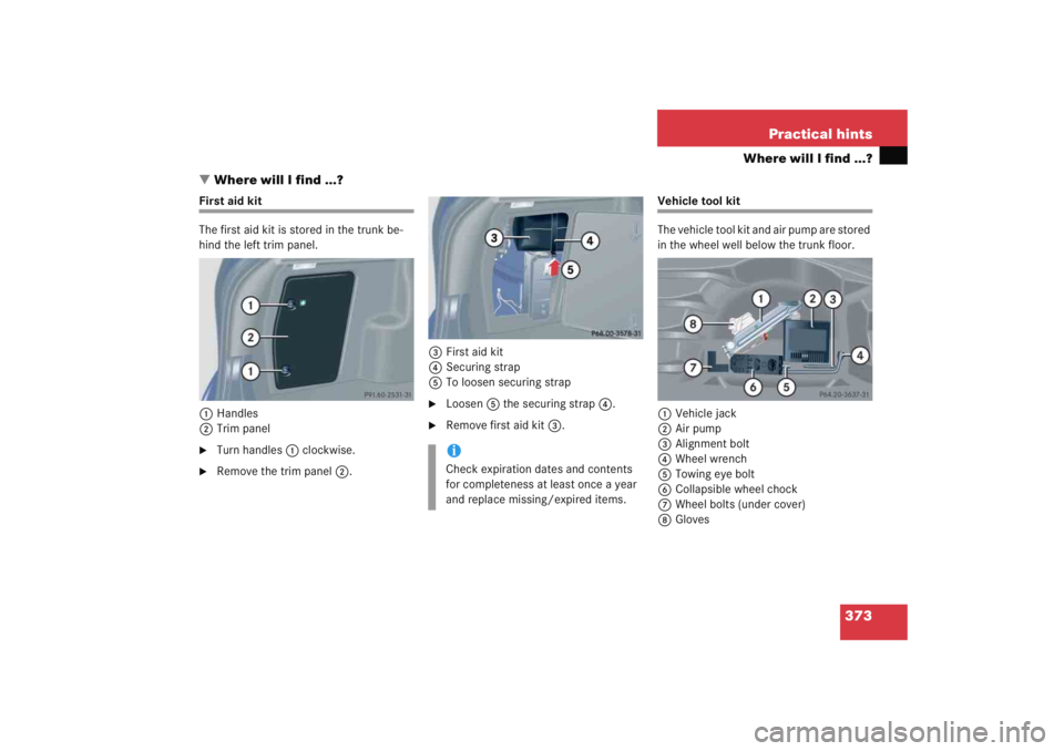
373
Practical hints
Where will I find ...?
� Where will I find ...?
First aid kit
The first aid kit is stored in the trunk be-
hind the left trim panel.
1 Handles
2 Trim panel�
Turn handles 1 clockwise.
�
Remove the trim panel 2. 3
First aid kit
4 Securing strap
5 To loosen securing strap
�
Loosen 5 the securing strap 4.
�
Remove first aid kit 3.
Vehicle tool kit
The vehicle tool kit and air pump are stored
in the wheel well below the trunk floor.
1 Vehicle jack
2 Air pump
3 Alignment bolt
4 Wheel wrench
5 Towing eye bolt
6 Collapsible wheel chock
7 Wheel bolts (under cover)
8 Gloves
iCheck expiration dates and contents
for completeness at least once a year
and replace missing/expired items.