Page 406 of 969

2122 Author�: Date�:
2005 LEXUS ES330 REPAIR MANUAL (RM1124U)
37. DISCONNECT STEERING GEAR OUTLET RETURN
TUBE
38. REMOVE GLOVE COM")
A60073
A59893
14-30
- ENGINE MECHANICALPARTIAL ENGINE ASSY (3MZ-FE)
2122 Author�: Date�:
2005 LEXUS ES330 REPAIR MANUAL (RM1124U)
37. DISCONNECT STEERING GEAR OUTLET RETURN
TUBE
38. REMOVE GLOVE COMPARTMENT DOOR ASSY (See page 10-22)
39. SEPARATE ENGINE WIRE
(a) Disconnect the engine wire harness from the ECM and
junction block.
(b) Disconnect the engine wire harness from the engine room
junction block.
(1) Remove the nut, then separate the engine wire har-
ness.
(2) Using a screwdriver, release the engine room junc-
tion block. Separate the engine wire harness by
pulling it upward.
(c) Remove the 2 nuts, then pull out the engine wire harness.
(d) Remove the body ground.
40. REMOVE EXHAUST PIPE NO.1 SUPPORT BRACKET FRONT (See page 15-2)
41. REMOVE EXHAUST PIPE NO.1 SUPPORT BRACKET REAR (See page 15-2)
42. REMOVE EXHAUST PIPE ASSY FRONT (See page 15-2)
43. DISCONNECT FRONT STABILIZER LINK ASSY LH (See page 30-8)
44. DISCONNECT FRONT STABILIZER LINK ASSY RH
HINT:
Perform the same procedure as above on the opposite side.
45. REMOVE FRONT AXLE HUB LH NUT (See page 30-8)
SST 09930-00010
46. REMOVE FRONT AXLE HUB RH NUT
SST 09930-00010
HINT:
Perform the same procedure as above on the opposite side.
47. SEPARATE SPEED SENSOR FRONT LH (See page 30-8)
48. SEPARATE SPEED SENSOR FRONT RH
HINT:
Perform the same procedure as above on the opposite side.
49. SEPARATE TIE ROD ASSY LH (See page 30-8)
SST 09628-6201 1
50. SEPARATE TIE ROD ASSY RH
SST 09628-6201 1
HINT:
Perform the same procedure as above on the opposite side.
Page 407 of 969

14-31
2123 Author�: Date�:
2005 LEXUS ES330 REPAIR MANUAL (RM1124U)
51. SEPARATE FRONT SUSPENSION ARM SUB-ASSY LOWER NO.1 LH (See")
A59877
A59878
A36439
- ENGINE MECHANICALPARTIAL ENGINE ASSY (3MZ-FE)
14-31
2123 Author�: Date�:
2005 LEXUS ES330 REPAIR MANUAL (RM1124U)
51. SEPARATE FRONT SUSPENSION ARM SUB-ASSY LOWER NO.1 LH (See page 30-8)
52. SEPARATE FRONT SUSPENSION ARM SUB-ASSY LOWER NO.1 RH
HINT:
Perform the same procedure as above on the opposite side.
53. SEPARATE FRONT AXLE ASSY LH (See page 30-8)
54. SEPARATE FRONT AXLE ASSY RH
HINT:
Perform the same procedure as above on the opposite side.
55. SEPARATE STEERING INTERMEDIATE SHAFT ASSY (See page 51-21)
56. REMOVE ENGINE ASSEMBLY WITH TRANSAXLE
(a) Set the engine lifter.
(b) Remove the 4 bolts and 2 nuts, then remove the frame
side rail plate RH and LH.
(c) Remove the 4 bolts and 2 nuts, then remove the front sus-
pension member brace rear RH and LH.
(d) Carefully remove the engine assembly from the vehicle.
(e) Install the engine hanger No. 2 in the correct direction as
shown in the illustration.
Torque: 20 NVm (199 kgfVcm, 14 ftVlbf)
HINT:
Engine hanger No. 212282-20020
Bolt91621-60822
(f) Attach the engine sling and hang the engine assembly
with the chain block.
57. REMOVE VANE PUMP V BELT (See page 14-5)
Page 408 of 969
A78549
A52890
A78403
RH: LH:
A60501
14-32
- ENGINE MECHANICALPARTIAL ENGINE ASSY (3MZ-FE)
2124 Author�: Date�:
2005 LEXUS ES330 REPAIR MANUAL (RM1124U)
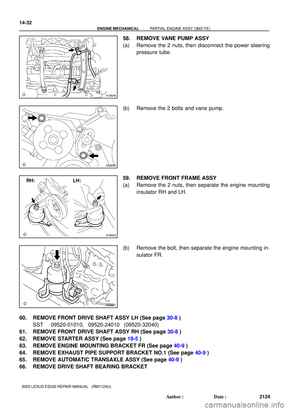
58. REMOVE VANE PUMP ASSY
(a) Remove the 2 nuts, then disconnect the power steering
pressure tube.
(b) Remove the 2 bolts and vane pump.
59. REMOVE FRONT FRAME ASSY
(a) Remove the 2 nuts, then separate the engine mounting
insulator RH and LH.
(b) Remove the bolt, then separate the engine mounting in-
sulator FR.
60. REMOVE FRONT DRIVE SHAFT ASSY LH (See page 30-8)
SST 09520-01010, 09520-24010 (09520-32040)
61. REMOVE FRONT DRIVE SHAFT ASSY RH (See page 30-8)
62. REMOVE STARTER ASSY (See page 19-5)
63. REMOVE ENGINE MOUNTING BRACKET FR (See page 40-9)
64. REMOVE EXHAUST PIPE SUPPORT BRACKET NO.1 (See page 40-9)
65. REMOVE AUTOMATIC TRANSAXLE ASSY (See page 40-9)
66. REMOVE DRIVE SHAFT BEARING BRACKET
Page 409 of 969

14-33
2125 Author�: Date�:
2005 LEXUS ES330 REPAIR MANUAL (RM1124U)
67. REMOVE DRIVE PLATE & RING GEAR SUB-ASSY (See")
A86565
A86566
A86567
3
472
5
6
1
- ENGINE MECHANICALPARTIAL ENGINE ASSY (3MZ-FE)
14-33
2125 Author�: Date�:
2005 LEXUS ES330 REPAIR MANUAL (RM1124U)
67. REMOVE DRIVE PLATE & RING GEAR SUB-ASSY (See page 14-140)
SST 09213-54015 (91651-60855), 09330-00021
68. INSTALL ENGINE STAND
69. REMOVE ENGINE HANGER NO.2
70. REMOVE EMISSION CONTROL VALVE SET (See page 11-13)
71. REMOVE INTAKE AIR SURGE TANK (See page 11-13)
72. REMOVE INTAKE MANIFOLD (See page 10-16)
73. REMOVE WATER OUTLET (See page 10-16)
74. REMOVE IGNITION COIL ASSY
75. REMOVE EXHAUST MANIFOLD HEAT INSULATOR NO.1 (See page 14-120)
76. REMOVE EXHAUST MANIFOLD SUB-ASSY RH (See page 14-120)
77. REMOVE MANIFOLD CONVERTER INSULATOR NO.3
(a) Remove the bolt and nut, then remove the insulator.
78. REMOVE EXHAUST MANIFOLD HEAT INSULATOR
NO.2
(a) Remove the 2 bolts and insulator.
79. REMOVE EXHAUST MANIFOLD CONVERTER
SUB-ASSY NO.2
(a) Using several steps, loosen and remove the 7 nuts in the
sequence shown in the illustration.
(b) Remove the exhaust manifold converter No. 2 and gasket
from the cylinder head LH.
Page 410 of 969

2126 Author�: Date�:
2005 LEXUS ES330 REPAIR MANUAL (RM1124U)
80. REMOVE MANIFOLD STAY NO.2
(a) Remove")
A86568
A05189
A80061
Oil Pressure
Switch 14-34
- ENGINE MECHANICALPARTIAL ENGINE ASSY (3MZ-FE)
2126 Author�: Date�:
2005 LEXUS ES330 REPAIR MANUAL (RM1124U)
80. REMOVE MANIFOLD STAY NO.2
(a) Remove the 2 bolts and manifold stay.
81. REMOVE ENGINE MOUNTING BRACKET RH (See page 17-9)
82. REMOVE PUMP BRACKET
(a) Remove the 3 bolts and pump bracket.
83. REMOVE GENERATOR BRACKET NO.1
84. REMOVE COMPRESSOR MOUNTING BRACKET NO.1 (See page 17-9)
85. REMOVE WATER INLET PIPE (See page 16-16)
86. REMOVE WATER INLET (See page 16-16)
87. REMOVE THERMOSTAT
88. REMOVE ENGINE OIL PRESSURE SWITCH ASSY
(a) Using a deep socket wrench 24 mm, remove the oil pres-
sure switch.
89. REMOVE KNOCK SENSOR (See page 10-16)
90. REPLACE PARTIAL ENGINE ASSY
91. INSTALL KNOCK SENSOR (See page 10-16)
92. INSTALL ENGINE OIL PRESSURE SWITCH ASSY
(a) Apply adhesive to 2 or 3 threads of the oil pressure switch.
Adhesive:
Part No. 08833-00080 THREE BOND 1344,
LOCTITE 242 or equivalent
(b) Using a deep socket wrench 24 mm, install the oil pressure switch.
Torque: 15 NVm (153 kgfVcm, 11 ftVlbf)
Page 411 of 969

14-35
2127 Author�: Date�:
2005 LEXUS ES330 REPAIR MANUAL (RM1124U)
93. INSTALL THERMOSTAT (See page 16-16)
94. INSTALL WATER INLET")
A86567
3
4
7
25
61
- ENGINE MECHANICALPARTIAL ENGINE ASSY (3MZ-FE)
14-35
2127 Author�: Date�:
2005 LEXUS ES330 REPAIR MANUAL (RM1124U)
93. INSTALL THERMOSTAT (See page 16-16)
94. INSTALL WATER INLET (See page 16-16)
95. INSTALL WATER INLET PIPE (See page 16-16)
96. INSTALL COMPRESSOR MOUNTING BRACKET NO.1 (See page 17-9)
97. INSTALL GENERATOR BRACKET NO.1
Torque: 58 NVm (591 kgfVcm, 43 ftVlbf)
98. INSTALL PUMP BRACKET
Torque: 32 NVm (326 kgfVcm, 24 ftVlbf)
99. INSTALL ENGINE MOUNTING BRACKET RH (See page 17-9)
100. INSTALL MANIFOLD STAY NO.2
Torque: 49 NVm (500 kgfVcm, 36 ftVlbf)
101. I N S TA L L E XHAUST MANIFOLD CONVERTER
SUB-ASSY NO.2
(a) Install a new gasket and the exhaust manifold converter
No. 2 with the 7 nuts. Using several steps, tighten the nuts
uniformly in the sequence shown in the illustration.
Torque: 49 NVm (500 kgfVcm, 36 ftVlbf)
(b) Retighten nuts 1 and 2 as shown in the illustration.
102. INSTALL EXHAUST MANIFOLD HEAT INSULATOR NO.2
Torque: 8.5 NVm (87 kgfVcm, 75 in.Vlbf)
103. INSTALL MANIFOLD CONVERTER INSULATOR NO.3
Torque: 8.5 NVm (87 kgfVcm, 75 in.Vlbf)
104. INSTALL EXHAUST MANIFOLD SUB-ASSY RH (See page 14-120)
105. INSTALL EXHAUST MANIFOLD HEAT INSULATOR NO.1 (See page 14-120)
106. INSTALL IGNITION COIL ASSY (See page 14-7)
107. INSTALL WATER OUTLET (See page 10-16)
108. INSTALL INTAKE MANIFOLD (See page 10-16)
109. INSTALL INTAKE AIR SURGE TANK (See page 11-13)
110. INSTALL EMISSION CONTROL VALVE SET (See page 11-13)
111. INSTALL DRIVE PLATE & RING GEAR SUB-ASSY (See page 14-140)
SST 09213-54015 (91651-60855), 09330-00021
112. INSTALL DRIVE SHAFT BEARING BRACKET
Torque: 64 NVm (650 kgfVcm, 47 in.Vlbf)
113. INSTALL AUTOMATIC TRANSAXLE ASSY (See page 40-9)
114. INSTALL EXHAUST PIPE SUPPORT BRACKET NO.1 (See page 40-9)
115. INSTALL ENGINE MOUNTING BRACKET FR (See page 40-9)
116. INSTALL STARTER ASSY (See page 19-5)
Page 412 of 969
A78403
RH: LH:
A60501
A52890
A78549
14-36
- ENGINE MECHANICALPARTIAL ENGINE ASSY (3MZ-FE)
2128 Author�: Date�:
2005 LEXUS ES330 REPAIR MANUAL (RM1124U)
117. INSTALL FRONT DRIVE SHAFT ASSY LH (See page 30-8)
118. INSTALL FRONT DRIVE SHAFT ASSY RH (See page 30-8)
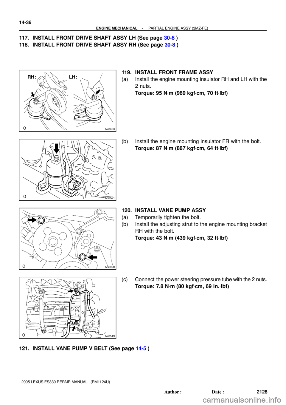
119. INSTALL FRONT FRAME ASSY
(a) Install the engine mounting insulator RH and LH with the
2 nuts.
Torque: 95 NVm (969 kgfVcm, 70 ftVlbf)
(b) Install the engine mounting insulator FR with the bolt.
Torque: 87 NVm (887 kgfVcm, 64 ftVlbf)
120. INSTALL VANE PUMP ASSY
(a) Temporarily tighten the bolt.
(b) Install the adjusting strut to the engine mounting bracket
RH with the bolt.
Torque: 43 NVm (439 kgfVcm, 32 ftVlbf)
(c) Connect the power steering pressure tube with the 2 nuts.
Torque: 7.8 NVm (80 kgfVcm, 69 in.Vlbf)
121. INSTALL VANE PUMP V BELT (See page 14-5)
Page 413 of 969

14-37
2129 Author�: Date�:
2005 LEXUS ES330 REPAIR MANUAL (RM1124U)
122. INSTALL ENGINE ASSEMBLY WITH TRANS")
A59877
BNut
A
BNut
A
A59878
Nut
D
CNut
D
C
- ENGINE MECHANICALPARTIAL ENGINE ASSY (3MZ-FE)
14-37
2129 Author�: Date�:
2005 LEXUS ES330 REPAIR MANUAL (RM1124U)
122. INSTALL ENGINE ASSEMBLY WITH TRANSAXLE
(a) Set the engine assembly with the transaxle on the engine
lifter.
(b) Install the engine assembly to the vehicle.
(c) Install the frame side rail plate RH and LH with the 4 bolts
and 2 nuts.
Torque:
85 NVm (867 kgfVcm, 63 ftVlbf) for bolt A
32 NVm (326 kgfVcm, 24 ftVlbf) for bolt B and nut
(d) Install the front suspension member brace rear RH and
LH with the 4 bolts and 2 nuts.
Torque:
85 NVm (867 kgfVcm, 63 ftVlbf) for bolt C
32 NVm (326 kgfVcm, 24 ftVlbf) for bolt D and nut
123. CONNECT STEERING INTERMEDIATE SHAFT ASSY (See page 51-21)
124. INSTALL FRONT AXLE ASSY LH (See page 30-8)
125. INSTALL FRONT AXLE ASSY RH
HINT:
Perform the same procedure as above on the opposite side.
126. INSTALL FRONT SUSPENSION ARM SUB-ASSY LOWER NO.1 LH (See page 30-8)
127. INSTALL FRONT SUSPENSION ARM SUB-ASSY LOWER NO.1 RH
HINT:
Perform the same procedure as above on the opposite side.
128. INSTALL TIE ROD ASSY LH (See page 30-8)
129. INSTALL TIE ROD ASSY RH
HINT:
Perform the same procedure as above on the opposite side.
130. INSTALL SPEED SENSOR FRONT LH (See page 30-8)
131. INSTALL SPEED SENSOR FRONT RH
HINT:
Perform the same procedure as above on the opposite side.
132. INSTALL FRONT AXLE HUB LH NUT (See page 30-8)
133. INSTALL FRONT AXLE HUB RH NUT
HINT:
Perform the same procedure as above on the opposite side.
134. INSTALL FRONT STABILIZER LINK ASSY LH (See page 30-8)
135. INSTALL FRONT STABILIZER LINK ASSY RH
HINT:
Perform the same procedure as above on the opposite side.
136. INSTALL EXHAUST PIPE ASSY FRONT (See page 15-2)
137. INSTALL EXHAUST PIPE NO.1 SUPPORT BRACKET REAR (See page 15-2)
138. INSTALL EXHAUST PIPE NO.1 SUPPORT BRACKET FRONT (See page 15-2)
139. CONNECT FUEL PIPE SUB-ASSY NO.1 (See page 11-1)