Page 743 of 969

5106B-04
F40531
SST
C92274
- POWER STEERINGRACK & PINION POWER STEERING GEAR ASSY
51-21
2596 Author�: Date�:
2005 LEXUS ES330 REPAIR MANUAL (RM1124U)
OVERHAUL
NOTICE:
When installing , coat the parts indicated by the arrow with power steering fluid or molybdenum disul-
fide lithium base grease (See page 51-18).
1. PRECAUTION(See page 60-1)
2. DISCONNECT BATTERY NEGATIVE TERMINAL
3. REMOVE HORN BUTTON ASSY
(See page 60-22)
4. REMOVE STEERING WHEEL ASSY
(See page 50-8)
SST 09950-50013 (09951-05010, 09952-05010, 09953-05020, 09954-05021)
5. REMOVE FRONT WHEEL
6. REMOVE SPIRAL CABLE SUB-ASSY
(See page 50-8)
7. DISCONNECT TIE ROD ASSY LH
(a) Remove the cotter pin and nut.
(b) Using SST, remove the tie rod assy LH from the steering
knuckle.
SST 09628-6201 1
8. DISCONNECT TIE ROD ASSY RH
SST 09628-6201 1
HINT:
Remove the RH side by the same procedures with LH side.
9. DISCONNECT STEERING INTERMEDIATE SHAFT
SUB-ASSY
(a) Loosen the bolt and remove the clamp from the steering
column hole cover No.1.
(b) Disconnect the steering column hole cover No.2 from the
steering column hole cover No.1.
(c) Loosen the bolt.
Page 758 of 969

ZX9390F41951
F40556
SST
51-36
- POWER STEERINGRACK & PINION POWER STEERING GEAR ASSY
2611 Author�: Date�:
2005 LEXUS ES330 REPAIR MANUAL (RM1124U)
50. INSPECT STEERING RACK END SUB-ASSY
(a) Ensure that the steering rack end sub-assy hole is not
clogged with grease.
HINT:
If the hole is clogged, the pressure inside the boot will change
after it is assembled and steering wheel is turned.
51. INSTALL STEERING RACK BOOT NO.2
(a) Install the steering rack boot No.2.
52. INSTALL STEERING RACK BOOT NO.1
HINT:
Remove the steering rack boot No.1 by the same procedures with steering rack boot No.2.
53. INSTALL STEERING RACK BOOT NO.2 CLAMP
(a) Using SST, tighten the steering rack boot No.2 clamp, as
shown in the illustration.
SST 09521-24010
Clearance: 3.0 mm (0.118 in.) or less
NOTICE:
Be careful not to damage the steering rack boot No.2.
54. INSTALL STEERING RACK BOOT NO.1 CLAMP
SST 09521-24010
NOTICE:
Be careful not to damage the steering rack boot No.1.
HINT:
Install the steering rack boot No.1 clamp by the same proce-
dures with steering rack boot No.2 clamp.
55. INSTALL STEERING RACK BOOT CLIP
(a) Using pliers, install the 2 steering rack boot clips.
56. INSTALL TIE ROD ASSY LH
(a) Screw the lock nut and tie rod assy LH onto the steering rack end sub-assy until the matchmarks are
aligned.
HINT:
After adjusting toe-in, torque the lock nut.
57. INSTALL TIE ROD ASSY RH
HINT:
Install the RH side by the same procedures with LH side.
Page 762 of 969
51-40
- POWER STEERINGRACK & PINION POWER STEERING GEAR ASSY
2615 Author�: Date�:
2005 LEXUS ES330 REPAIR MANUAL (RM1124U)
68. CONNECT TIE ROD ASSY LH
(a) Connect the tie rod assy LH with the nut.
Torque: 49 NVm (500 kgfVcm, 36 ftVlbf)
(b) Install a new cotter pin.
NOTICE:
If the holes for a new cotter pin are not aligned, tighten the nut further up 60�.
69. CONNECT TIE ROD ASSY RH
HINT:
Install the RH side by the same procedures with LH side.
70. INSTALL FRONT WHEEL
Torque: 103 NVm (1,050 kgfVcm, 76 ftVlbf)
71. BLEED POWER STEERING FLUID (See page 51-3)
72. CHECK POWERSTEERING FLUID LEAKAGE
73. INSTALL SPIRAL CABLE SUB-ASSY
(See page 50-8)
74. CENTER SPIRAL CABLE(See page 50-8)
75. INSTALL STEERING WHEEL ASSY
(See page 50-8)
76. INSTALL HORN BUTTON ASSY
(See page 60-22)
77. INSPECT AND ADJUST FRONT WHEEL ALIGNMENT(See page 26-5)
78. INSPECT STEERING WHEEL CENTER POINT
79. INSPECT SRS WARNING LIGHT(See page 05-826)
Page 811 of 969

5002K-07
50-2
- STEERING COLUMNSTEERING
2563 Author�: Date�:
2005 LEXUS ES330 REPAIR MANUAL (RM1124U)
PROBLEM SYMPTOMS TABLE
Use the table below to help you find the cause of the problem. The numbers indicate the priority of the likely
cause of the problem. Check each part in the order shown. If necessary, repair or replace these parts.
SymptomSuspect AreaSee page
Hard steering
1. Tires (Improperly inflated)
2. Power steering fluid level (Low)
3. Drive belt (Loose)
4. Front wheel alignment (Incorrect)
5. Steering system joints (Worn)
6. Suspension arm ball joints (Worn)
7. Steering column (Binding)
8. Power steering vane pump
9. Power steering gear28-1
51-3
51-3
51-3
26-5
-
26-16
-
51-9
51-21
Poor return
1. Tires (Improperly inflated)
2. Front wheel alignment (Incorrect)
3. Steering column (Binding)
4. Power steering gear28-1
26-5
-
51-21
Excessive play
1. Steering system joints (Worn)
2. Suspension arm ball joints (Worn)
3. Intermediate shaft, Sliding yoke (Worn)
4. Front wheel bearing (Worn)
5. Power steering gear-
26-16
-
30-19
51-21
Abnormal noise
1. Power steering fluid level (Low)
2. Steering system joints (Worn)
3. Power steering vane pump
4. Power steering gear51-3
-
51-9
51-21
Page 812 of 969
5002L-03
H41575
Maximum
Freeplay
30 mm (1.18 in.)
- STEERING COLUMNSTEERING
50-3
2564 Author�: Date�:
2005 LEXUS ES330 REPAIR MANUAL (RM1124U)
ON-VEHICLE INSPECTION
1. CHECK STEERING WHEEL FREEPLAY
(a) Stop the vehicle and face the tires straight ahead.
(b) Rock the steering wheel gently up and down with your
hand, check the steering wheel freeplay.
Maximum freeplay: 30 mm (1.18 in.)
Page 813 of 969

5002V-03
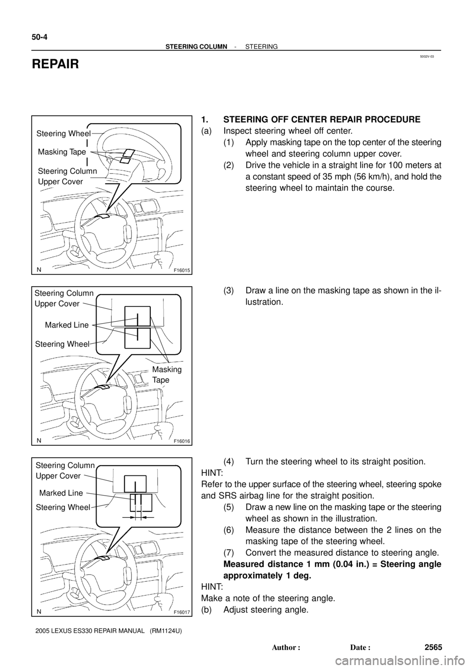
F16015
Steering Wheel
Masking Tape
Steering Column
Upper Cover
F16016
Steering Wheel
Masking
Tape Steering Column
Upper Cover
Marked Line
F16017
Steering Wheel Steering Column
Upper Cover
Marked Line
50-4
- STEERING COLUMNSTEERING
2565 Author�: Date�:
2005 LEXUS ES330 REPAIR MANUAL (RM1124U)
REPAIR
1. STEERING OFF CENTER REPAIR PROCEDURE
(a) Inspect steering wheel off center.
(1) Apply masking tape on the top center of the steering
wheel and steering column upper cover.
(2) Drive the vehicle in a straight line for 100 meters at
a constant speed of 35 mph (56 km/h), and hold the
steering wheel to maintain the course.
(3) Draw a line on the masking tape as shown in the il-
lustration.
(4) Turn the steering wheel to its straight position.
HINT:
Refer to the upper surface of the steering wheel, steering spoke
and SRS airbag line for the straight position.
(5) Draw a new line on the masking tape or the steering
wheel as shown in the illustration.
(6) Measure the distance between the 2 lines on the
masking tape of the steering wheel.
(7) Convert the measured distance to steering angle.
Measured distance 1 mm (0.04 in.) = Steering angle
approximately 1 deg.
HINT:
Make a note of the steering angle.
(b) Adjust steering angle.
Page 815 of 969
5002H-02
C90698
Steering Column
CoverHorn Button Assy
Steering Wheel Assy
Steering Pad SwitchConnector
Cover
Turn Signal Switch Assy
50 (510, 37)
Steering Column Cover
Lower No.2Instrument Panel
Finish Plate
NVm (kgfVcm, ftVlbf) : Specified torque
21 (214, 15)
8.8 (90, 78 in.Vlbf)
Steering Wheel
Cover Lower No. 2
Instrument Panel Sub-assy Upper
Steering Column Assy
Steering Column Hole
Cover Sub-assy No. 2
Hose Clamp
Heater to Foot
Duct No. 3
Steering Intermediate
Shaft Sub-assyInstrument Panel Insert
Sub-assy Lower LH
Front Door Scuff Plate LH
35 (360, 26)
35 (360, 26)
21 (214, 15)
50-6
- STEERING COLUMNSTEERING COLUMN ASSY
2567 Author�: Date�:
2005 LEXUS ES330 REPAIR MANUAL (RM1124U)
STEERING COLUMN ASSY
COMPONENTS
Page 817 of 969

5002I-04
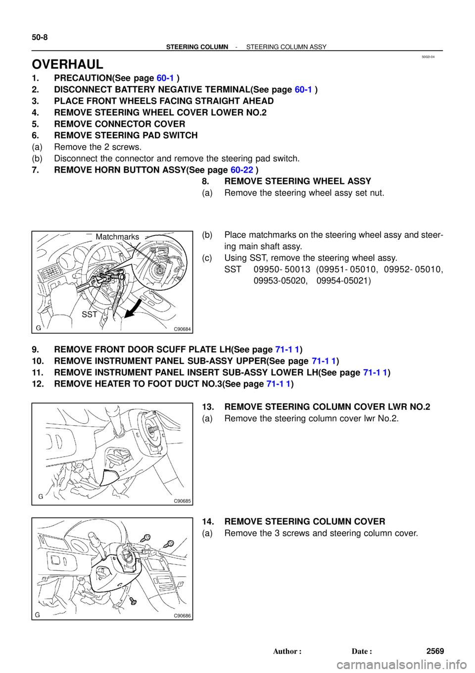
C90684
Matchmarks
SST
C90685
C90686
50-8
- STEERING COLUMNSTEERING COLUMN ASSY
2569 Author�: Date�:
OVERHAUL
1. PRECAUTION(See page 60-1)
2. DISCONNECT BATTERY NEGATIVE TERMINAL(See page 60-1)
3. PLACE FRONT WHEELS FACING STRAIGHT AHEAD
4. REMOVE STEERING WHEEL COVER LOWER NO.2
5. REMOVE CONNECTOR COVER
6. REMOVE STEERING PAD SWITCH
(a) Remove the 2 screws.
(b) Disconnect the connector and remove the steering pad switch.
7. REMOVE HORN BUTTON ASSY(See page 60-22)
8. REMOVE STEERING WHEEL ASSY
(a) Remove the steering wheel assy set nut.
(b) Place matchmarks on the steering wheel assy and steer-
ing main shaft assy.
(c) Using SST, remove the steering wheel assy.
SST 09950- 50013 (09951- 05010, 09952- 05010,
09953-05020, 09954-05021)
9. REMOVE FRONT DOOR SCUFF PLATE LH(See page 71-1 1)
10. REMOVE INSTRUMENT PANEL SUB-ASSY UPPER(See page 71-1 1)
11. REMOVE INSTRUMENT PANEL INSERT SUB-ASSY LOWER LH(See page 71-1 1)
12. REMOVE HEATER TO FOOT DUCT NO.3(See page 71-1 1)
13. REMOVE STEERING COLUMN COVER LWR NO.2
(a) Remove the steering column cover lwr No.2.
14. REMOVE STEERING COLUMN COVER
(a) Remove the 3 screws and steering column cover.