Page 822 of 969
C90690
C90688
Matchmarks
- STEERING COLUMNSTEERING COLUMN ASSY
50-13
2574 Author�: Date�:
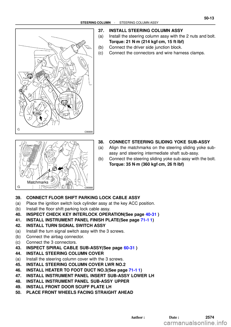
37. INSTALL STEERING COLUMN ASSY
(a) Install the steering column assy with the 2 nuts and bolt.
Torque: 21 NVm (214 kgfVcm, 15 ftVlbf)
(b) Connect the driver side junction block.
(c) Connect the connectors and wire harness clamps.
38. CONNECT STEERING SLIDING YOKE SUB-ASSY
(a) Align the matchmarks on the steering sliding yoke sub-
assy and steering intermediate shaft sub-assy.
(b) Connect the steering sliding yoke sub-assy with the bolt.
Torque: 35 NVm (360 kgfVcm, 26 ftVlbf)
39. CONNECT FLOOR SHIFT PARKING LOCK CABLE ASSY
(a) Place the ignition switch lock cylinder assy at the key ACC position.
(b) Install the floor shift parking lock cable assy.
40. INSPECT CHECK KEY INTERLOCK OPERATION(See page 40-31)
41. INSTALL INSTRUMENT PANEL FINISH PLATE(See page 71-1 1)
42. INSTALL TURN SIGNAL SWITCH ASSY
(a) Install the turn signal switch assy with the 3 screws.
(b) Connect the airbag connector.
(c) Connect the 3 connectors.
43. INSPECT SPIRAL CABLE SUB-ASSY(See page 60-31)
44. INSTALL STEERING COLUMN COVER
(a) Install the steering column cover with the 3 screws.
45. INSTALL STEERING COLUMN COVER LWR NO.2
46. INSTALL HEATER TO FOOT DUCT NO.3(See page 71-1 1)
47. INSTALL INSTRUMENT PANEL INSERT SUB-ASSY LOWER LH
48. INSTALL INSTRUMENT PANEL SUB-ASSY UPPER
49. INSTALL FRONT DOOR SCUFF PLATE LH
50. PLACE FRONT WHEELS FACING STRAIGHT AHEAD
Page 823 of 969
50-14
- STEERING COLUMNSTEERING COLUMN ASSY
2575 Author�: Date�:
51. INSTALL STEERING WHEEL ASSY
(a) Align the matchmarks on the steering wheel assy and steering main shaft assy.
(b) Install the steering wheel assy set nut.
Torque: 50 NVm (510 kgfVcm, 37 ftVlbf)
52. INSPECT HORN BUTTON ASSY(See page 60-22)
53. INSTALL HORN BUTTON ASSY(See page 60-22)
54. INSTALL STEERING PAD SWITCH
(a) Connect the connector.
(b) Install the steering pad switch with the 2 screws.
55. INSTALL CONNECTOR COVER
56. INSTALL STEERING WHEEL COVER LOWER NO.2
57. INSPECT SRS WARNING LIGHT(See page 05-818)
Page 946 of 969
Lexus Supports ASE CertificationPage 1 of 2
Title:
STEERING INTERMEDIATE SHAFT NOISE
Models:
'03 ES 300, '04 ± '05 ES 330
Technical Service
Information Bulletin
April 29, 2005
ST001-05
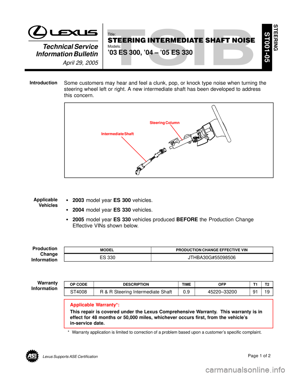
Some customers may hear and feel a clunk, pop, or knock type noise when turning the
steering wheel left or right. A new intermediate shaft has been developed to address
this concern.
Intermediate Shaft
Steering Column
�2003 model year ES 300 vehicles.
�2004 model year ES 330 vehicles.
�2005 model year ES 330 vehicles produced BEFORE the Production Change
Effective VINs shown below.
MODELPRODUCTION CHANGE EFFECTIVE VIN
ES 330JTHBA30G#55098506
OP CODEDESCRIPTIONTIMEOFPT1T2
ST4008R & R Steering Intermediate Shaft0.945220±332009119
Applicable Warranty*:
This repair is covered under the Lexus Comprehensive Warranty. This warranty is in
effect for 48 months or 50,000 miles, whichever occurs first, from the vehicle's
in-service date.
* Warranty application is limited to correction of a problem based upon a customer's specific complaint.
STEERING
Introduction
Applicable
Vehicles
Production
Change
Information
Warranty
Information
Page 947 of 969
STEERING INTERMEDIATE SHAFT NOISE ± ST001-05 April 29, 2005
Page 2 of 2
PREVIOUS PART NUMBERCURRENT PART NUMBERPART NAMEQTY
45220±3320045220±33240Intermediate Shaft Assembly1
Prior to removing the steering intermediate shaft, make sure the steering wheel and front
wheels remain stationary. Once the intermediate shaft is removed, do NOT allow the
steering wheel to spin freely.
For information on replacing the steering intermediate shaft assembly, refer to the
Technical Information System (TIS): 2003 ± 2004 model year ES 330 Repair Manual:
Steering Column: Steering Column Assy: Overhaul.
Parts
Information
Repair
Procedure
Page 948 of 969
Lexus Supports ASE CertificationPage 1 of 11
Title:
REPAIR MANUAL SUPPLEMENT:
VEHICLE PULLING TO ONE SIDE
Models:
All '02 ± '06 Model
Technical Service
Information Bulletin
December 21, 2001
ST004-01
TSIB REVISION NOTICE:
�October 5, 2005: 2003 ± 2006 model years have been added to Applicable Vehicles.
A note has been added to the illustration in step 3.
�March 1, 2002: OP Codes updated in Warranty Information.
All previous versions of this TSIB should be discarded.
This bulletin contains general vehicle pulling diagnosis and repair procedures along with
specific information to help correct pulling complaints.
This information supplements Repair Manual procedures when the symptoms are:
�The driver holds the steering wheel without exerting steering effort while driving
straight ahead, and the vehicle drifts to the right or the left.
�While driving straight ahead, the driver has to steer either to the right or the left to
maintain straight driving.
�2002 ± 2006 model year Lexus vehicles.
OP CODEDESCRIPTIONTIMEOPNT1T2
ST1004Preliminary Check & Road Test0.6
Combo ASwitch Front Tire/Wheel & Road Test0.5
Combo BReverse the Front One Side Tire0.745046 09020Combo CCheck Front Wheel Alignment1.245046±09020
Combo DAdjust Front Wheel Alignment0.73199
Combo EAdjust Camber Setting0.7
420091Dismount and Mount Tire and Balance Wheel
and Tire Assembly0.542611±48030
Combo AEach additional Wheel0.3
42611 48030
NOTE:
Above combination codes A, B, D and E include road test time.
Applicable Warranty*:
This repair is covered under the Lexus Comprehensive Warranty. This warranty is in
effect for 12 months or 20,000 miles, whichever occurs first, from the vehicle's
in-service date.
* Warranty application is limited to correction of a problem based upon a customer's specific complaint.
STEERING
Introduction
Applicable
Vehicles
Warranty
Information
Page 950 of 969
REPAIR MANUAL SUPPLEMENT: VEHICLE PULLING TO ONE SIDE ± ST004-01 RevisedDecember 21, 2001
Page 3 of 11
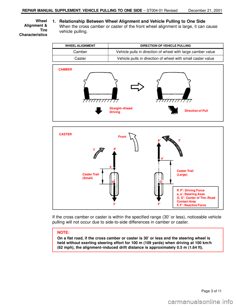
1. Relationship Between Wheel Alignment and Vehicle Pulling to One Side
When the cross camber or caster of the front wheel alignment is large, it can cause
vehicle pulling.
WHEEL ALIGNMENTDIRECTION OF VEHICLE PULLING
CamberVehicle pulls in direction of wheel with large camber value
CasterVehicle pulls in direction of wheel with small caster value
CAMBER
Straight±Ahead
DrivingDirection of Pull
CASTER
Front
Caster Trail
(Small)Caster Trail
(Large) TPT' P'
F' F aa'
O
P, P': Driving Force
a, a': Steering Axes
O, O': Center of Tire±Road
Contact Area
F, F': Reactive Force
O'
If the cross camber or caster is within the specified range (30' or less), noticeable vehicle
pulling will not occur due to side-to-side differences in camber or caster.
NOTE:
On a flat road, if the cross camber or caster is 30' or less and the steering wheel is
held without exerting steering effort for 100 m (109 yards) when driving at 100 km/h
(62 mph), the alignment±induced drift distance is approximately 0.5 m (1.64 ft). Wheel
Alignment &
Tire
Characteristics
Page 951 of 969
REPAIR MANUAL SUPPLEMENT: VEHICLE PULLING TO ONE SIDE ± ST004-01 RevisedDecember 21, 2001
Page 4 of 11
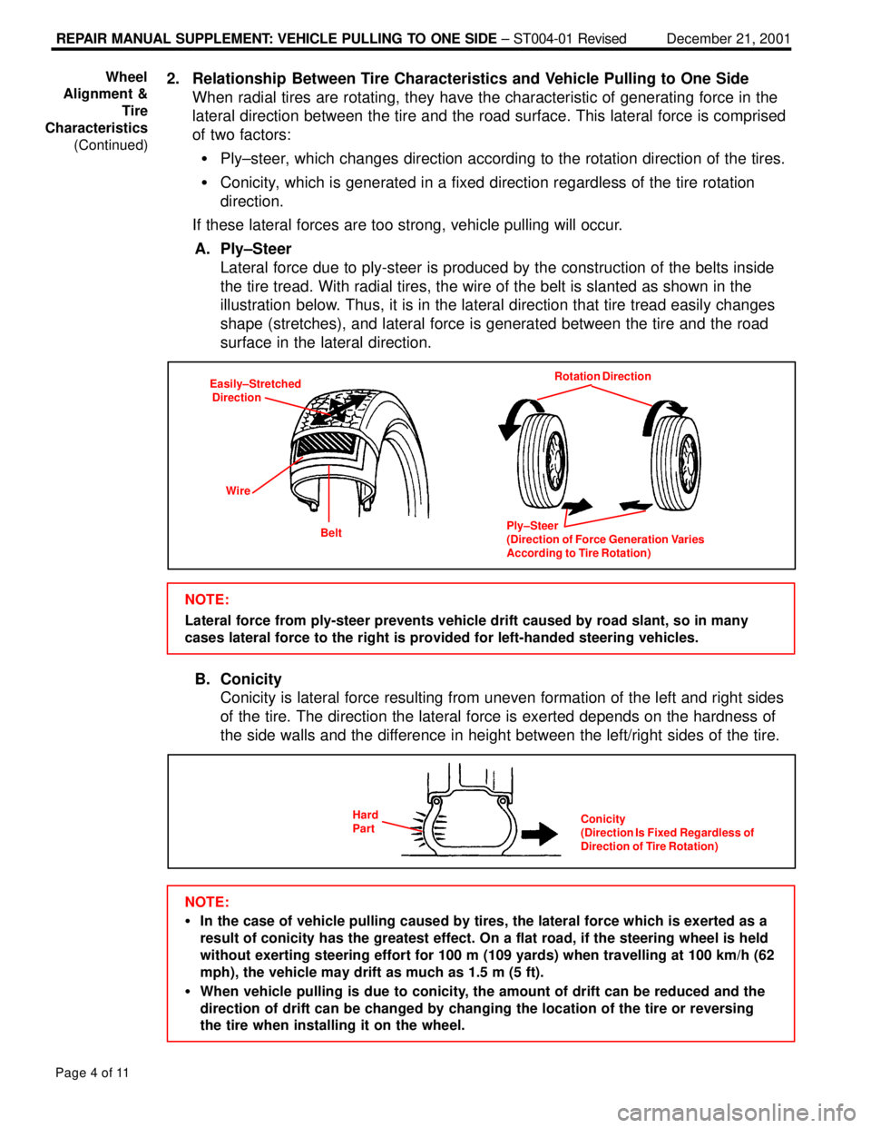
2. Relationship Between Tire Characteristics and Vehicle Pulling to One Side
When radial tires are rotating, they have the characteristic of generating force in the
lateral direction between the tire and the road surface. This lateral force is comprised
of two factors:
�Ply±steer, which changes direction according to the rotation direction of the tires.
�Conicity, which is generated in a fixed direction regardless of the tire rotation
direction.
If these lateral forces are too strong, vehicle pulling will occur.
A. Ply±Steer
Lateral force due to ply-steer is produced by the construction of the belts inside
the tire tread. With radial tires, the wire of the belt is slanted as shown in the
illustration below. Thus, it is in the lateral direction that tire tread easily changes
shape (stretches), and lateral force is generated between the tire and the road
surface in the lateral direction.
Easily±Stretched
Direction
Wire
BeltRotation Direction
Ply±Steer
(Direction of Force Generation Varies
According to Tire Rotation)
NOTE:
Lateral force from ply-steer prevents vehicle drift caused by road slant, so in many
cases lateral force to the right is provided for left-handed steering vehicles.
B. Conicity
Conicity is lateral force resulting from uneven formation of the left and right sides
of the tire. The direction the lateral force is exerted depends on the hardness of
the side walls and the difference in height between the left/right sides of the tire.
Conicity
(Direction Is Fixed Regardless of
Direction of Tire Rotation) Hard
Part
NOTE:
�In the case of vehicle pulling caused by tires, the lateral force which is exerted as a
result of conicity has the greatest effect. On a flat road, if the steering wheel is held
without exerting steering effort for 100 m (109 yards) when travelling at 100 km/h (62
mph), the vehicle may drift as much as 1.5 m (5 ft).
�When vehicle pulling is due to conicity, the amount of drift can be reduced and the
direction of drift can be changed by changing the location of the tire or reversing
the tire when installing it on the wheel. Wheel
Alignment &
Tire
Characteristics
(Continued)
Page 952 of 969
REPAIR MANUAL SUPPLEMENT: VEHICLE PULLING TO ONE SIDE ± ST004-01 RevisedDecember 21, 2001
Page 5 of 11
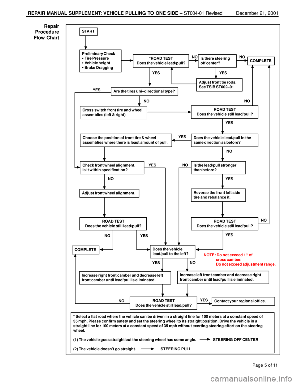
* Select a flat road where the vehicle can be driven in a straight line for 100 meters at a constant speed of
35 mph. Please confirm safety and set the steering wheel to its straight position. Drive the vehicle in a
straight line for 100 meters at a constant speed of 35 mph without exerting steering effort on the steering
wheel.
(1) The vehicle goes straight but the steering wheel has some angle. STEERING OFF CENTER
(2) The vehicle doesn't go straight. STEERING PULLYES
START
Preliminary Check
� Tire Pressure
� Vehicle height
� Brake Dragging*ROAD TEST
Does the vehicle lead/pull?Is there steering
off center?COMPLETE
Adjust front tie rods.
See TSIB ST002±01
Are the tires uni±directional type?
Cross switch front tire and wheel
assemblies (left & right)ROAD TEST
Does the vehicle still lead/pull?
Does the vehicle lead/pull in the
same direction as before?
Is the lead/pull stronger
than before?
Reverse the front left side
tire and rebalance it.
ROAD TEST
Does the vehicle still lead/pull?
Increase left front camber and decrease right
front camber until lead/pull is eliminated.
Does the vehicle
lead/pull to the left?
ROAD TEST
Does the vehicle still lead/pull?
Increase right front camber and decrease left
front camber until lead/pull is eliminated.
Contact your regional office.
COMPLETE
Choose the position of front tire & wheel
assemblies where there is least amount of pull.
Check front wheel alignment.
Is it within specification?
ROAD TEST
Does the vehicle still lead/pull?
Adjust front wheel alignment.
NOTE: Do not exceed 1� of
cross camber.
Do not exceed adjustment range.
NO YES YES
YES
YES
YESNO
NO YES
NO NO YESNO YESYES YES
NONO NO
NO NO
Repair
Procedure
Flow Chart